EP0045951A2 - Process for operating an inverter with an intermediate DC link circuit supplying an electric synchronous motor - Google Patents
Process for operating an inverter with an intermediate DC link circuit supplying an electric synchronous motor Download PDFInfo
- Publication number
- EP0045951A2 EP0045951A2 EP81106171A EP81106171A EP0045951A2 EP 0045951 A2 EP0045951 A2 EP 0045951A2 EP 81106171 A EP81106171 A EP 81106171A EP 81106171 A EP81106171 A EP 81106171A EP 0045951 A2 EP0045951 A2 EP 0045951A2
- Authority
- EP
- European Patent Office
- Prior art keywords
- converter
- commutation
- speed
- speed range
- inverter
- Prior art date
- Legal status (The legal status is an assumption and is not a legal conclusion. Google has not performed a legal analysis and makes no representation as to the accuracy of the status listed.)
- Granted
Links
Images

Classifications
-
- H—ELECTRICITY
- H02—GENERATION; CONVERSION OR DISTRIBUTION OF ELECTRIC POWER
- H02P—CONTROL OR REGULATION OF ELECTRIC MOTORS, ELECTRIC GENERATORS OR DYNAMO-ELECTRIC CONVERTERS; CONTROLLING TRANSFORMERS, REACTORS OR CHOKE COILS
- H02P25/00—Arrangements or methods for the control of AC motors characterised by the kind of AC motor or by structural details
- H02P25/02—Arrangements or methods for the control of AC motors characterised by the kind of AC motor or by structural details characterised by the kind of motor
- H02P25/022—Synchronous motors
- H02P25/03—Synchronous motors with brushless excitation
Definitions
- the invention relates to a method for operating a converter with a DC link, an inverter with converter valves in a three-phase bridge circuit and a three-phase machine as a load, in which at speeds of the three-phase machine that are greater than a machine-related minimum speed, the converter is load-guided and the commutation voltage for the converter valves Inverter is supplied by the induction machine and in which at speeds that are lower than the minimum speed, the converter valves of the inverter are commutated with an auxiliary commutation device, wherein at least at speeds that are greater than the minimum speed, six times cyclical commutation takes place in one rotation period, alternating in both bridge halves of the three-phase bridge from the converter valve of a converter branch to a subsequent current-carrying converter valve of a converter branch of the same bridge half is commutated.
- Such a method for operating such a converter also known as a converter motor, is known, for example, from Siemens magazine 45 (1971), pages 753 to 757 or from DE-PS 22 46 562.
- the inverter is clocked with this inverter. load-dependent, the commutation reactive power is supplied by the three-phase machine of synchronous design.
- the known auxiliary commutation methods reach their limit frequency before the required minimum speed is reached and the now load-controlled inverter can commutate the motor current with the aid of the machine voltage.
- other complex starting devices for example starting motors or starting transformers, must be used.
- this object is achieved in that the speeds, which are lower than the minimum speeds, are divided into at least two speed ranges, that in a first speed range starting at zero speed, the six times commutation per rotation period is maintained and that in one the Cyclic commutation takes place three times per rotation period in the first speed range, subsequent second speed range, during which each commutation in the converter branches of both bridge halves of the three-phase bridge circuit is simultaneously commutated from the converter valve of one converter branch to a subsequent current-carrying converter valve of another converter branch.
- a third speed range adjoining the second speed range there is only two cyclic commutation per rotation period, the three-phase bridge being operated as a single-phase bridge, for which purpose the converter valves of two converter branches with a common main connection remain unignited.
- the third speed range which now ends with the required minimum speed, only every third commutation is carried out in the inverter.
- the speed range of the forced commutation with respect to the cutoff frequency of each of the conventional auxiliary commutation methods can thus be tripled.
- the mean value of the torque in this third speed range drops only slightly compared to the torque mean in the second speed range and the torque ripple also increases only insignificantly.
- FIG. 1 shows the circuit of a converter motor.
- a controlled inverter WR is made up of controllable converter valves 1 to 6 in a three-phase bridge circuit.
- the converter branches 1a to 3a and 4a to 6a of each bridge half WR1 and WR2 are connected via their common main connections 7 to 9 to the three-phase winding of a synchronous machine 10, to which the machine voltage u, v and w is applied during operation.
- the inverter WR is made of a three-phase mains R, S, T via a controlled rectifier 11 and a DC intermediate circuit 12 with DC link or smoothing inductor 13 - fed.
- the rectifier 11 is constructed from six controllable converter valves 11a to 11f in a three-phase bridge circuit.
- the controllable electricity Rectifier valves 1 to 6 of the inverter WR and the controllable converter valves 11a to 11f of the rectifier 11 can be, for example, thyristors.
- the signals of the rotor position sensor 15 are fed to a changeover switch 16.
- the signals of the tachodynamo 14 representing the actual speed value are compared in an adding stage 17 with a desired speed value which is fed to the adding stage 17 via an input 18.
- the control deviation obtained is due to a speed controller 19, the output of which is fed to a second adder 21 to compare its signal voltage with the signals of a current transformer 20.
- the current transformer 20 is arranged in the three-phase feed line.
- the adder stage 21 is followed by a current regulator 22, from which the converter valves 11a to 11f of the rectifier 11 are controlled via lines 23.
- the actual speed value recorded with the tachodynamo 14 is also fed to the input 24a of a limit value detector 24.
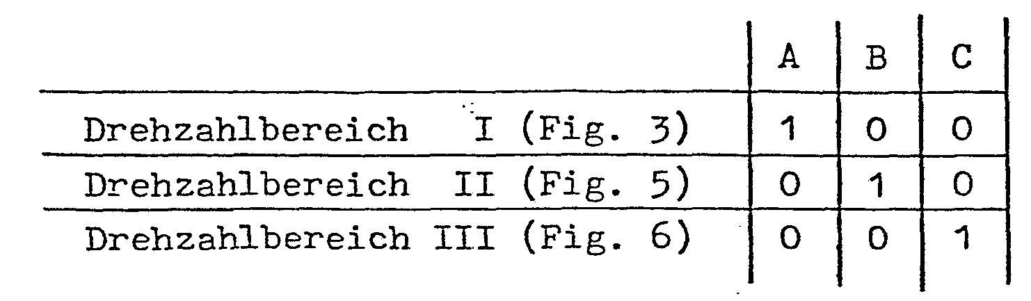
- the limit value indicator 24 generates a signal A in a first speed range I, which begins at zero speed, a signal B in a second speed range II, which connects to the first speed range I, and in a third speed range II, which with the machine-related minimum speed ends, a signal C.
- the limit value indicator When the minimum speed is exceeded, the limit value indicator finally generates a signal D.
- These signals A to D are present at the outputs 24A to 24D of the limit value indicator 24, which have the same capital letters.
- the outputs 24A to 24C of the Limit detectors 24 are connected to inputs 25A to 25C of a first control set 25, from which the controllable converter valves 1 to 6 of the inverter WR are controlled via lines 26.
- the output 24D of the limit value detector 24 is connected to the actuation input 16a of the changeover switch 16.
- the output of the rotor position sensor 15 is linked to an input 25H of the tax rate 25 via the normally closed contact of the switch 16.
- the make contact of the switch 16 is connected to an input 27a of a second headset 27.
- the signal D switches the output of the rotor position sensor 15 from the input 25H of the tax rate 25 to the input 27H of the tax rate 27.
- the controllable converter valves 1 to 6 of the inverter WR are also controlled by the control unit 27 via lines 28. The structure of the two tax rates 25 and 27 will be discussed in more detail below.
- a switch 29 is provided as an auxiliary commutation device in the converter motor according to FIG. 1, which bridges the intermediate circuit inductance 13 in a known manner and short-circuits it in the closed state.
- the actuation input 29a of the switch 29 is connected to an output 25a of the first headset 25.
- the switch 29 is closed via a signal that is briefly present at the actuation input 29a, whereby the intermediate circuit choke is short-circuited in a known manner for each commutation and the intermediate circuit current is thus briefly made zero for each commutation.
- any other auxiliary commutation method according to the invention Procedure can be operated.
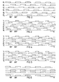
- FIG. 1 shows the signals H 1 to H 32 generated by the rotor position sensor 15, the length of each of which is 180 ° el and which are shifted from one another by 120 ° el.
- the inverted signal H 1 to H 3 is generated in an inverting element (not shown in FIG. 1).
- the signals H 1 to H 3 and H 1 to H 3 are fed via the changeover switch 16 to the input 25H of the tax rate 25 as long as the speed of the motor 10 is less than its minimum speed.
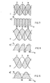
- the speed range I which is determined by the signal A of the limit value detector 24, the following logical logic equations are used generates the ignition pulses T 1 to T 6 shown in FIG. 3 for the converter valves 1 to 6, the reference numerals of which correspond to the index of the corresponding ignition pulse T. It can be seen from the pulse diagram in FIG.
- FIG. 4 and FIG. 5 show that in the speed range II only every second commutation takes place in each rotation period, that is to say commutation only three times per rotation period.
- a converter valve for example converter valves 1 and 6 according to FIG. 5, is simultaneously commutated to the converter valve 2 and 4 which subsequently carries current.
- the speed range of the forced commutation thus obtained with the auxiliary commutation device 29 unchanged is twice as large as the limit frequency in the speed range I.
- the pulse grid thus generated and shown in FIG. 6 illustrates that the three-phase bridge WR is operated as a single-phase bridge in the speed range III, for which purpose the converter valves of two converter branches with a common main connection in the entire speed range III, for example the converter valves 2 and 5 with the common main connection according to FIG 8 remain ignited.
- auxiliary commutation device 29 a speed range for the forced commutation is obtained which is three times that.
- Limit frequency of the auxiliary commutation process is reached in the speed range I. After the machine-related minimum frequency has been exceeded, signal D is only present at output 24D of limit value detector 24.
- FIG. 7 shows normal commutation in the speed range I.
- the mean torque M m of the synchronous motor 10 thus obtained is 95% of the peak value M, as shown in FIG. 7 with the dash-dotted line 30.
- FIG. 8 shows the profile of the machine voltages u, v and w in the speed range II and the associated torque profile M, FIG. 8 being based on cyclic commutation in both bridge branches WR1 and WR2 at intervals of 120 ° el in accordance with FIG. 5.
- the broken line 31 shows that the average torque M m has decreased compared to the torque obtained in the speed range I and is 71% of the peak value M.
- the ripple of the torque curve has also increased. In most applications, neither the drop in the average torque nor the greater torque ripple play a role. This applies in particular if the converter according to FIG. 1 is used to drive fans, centrifuges, compressors, etc.
- FIG. 8 also shows the advantage of the commutation method according to FIG.
- FIG. 9 shows the profile of u, v and w and the torque profile M in the speed range III, in which commutation according to a single-phase bridge only takes place after 180 ° el.
- the dashed line 32 which in turn indicates the size of the average torque M m , shows that the average torque M m in the speed range III has decreased only slightly compared to the speed range II.
- the average torque M m is 64% of the maximum torque M.
- the torque ripple has increased again, but as already emphasized above, this does not play a significant role in most applications.
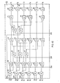
- FIG. 10 shows an exemplary embodiment of the control set 25, with which the converter valves 1 to 6 of the inverter WR are driven at speeds which lie in the speed ranges I to III, the switches of the auxiliary commutation device 29 being closed at the same time to initiate each commutation.
- the signals H 1 to H 3 are present in pairs at the inputs 25H, as are indicated by the logic equations in connection with FIG. 3.
- the respectively assigned signals H 1 to H 3 are shown in FIG. 10.
- a logic logic element with a conjunctive logic element 33 to 38 is connected downstream of two inputs 25H assigned to each other.
- the output of each AND gate 33 to 38 is fed to the first input of a further AND gate 39 to 44.
- each AND gate 39 is connected to the input 25A, at which the signal A of the limit value detector 24 is present.
- the output of each AND gate 39 to 44 is followed by an input of a logical logic element with a disconjunctive logic 45 to 50.
- the second input of the OR gates 45 and 50 is connected to the output of an AND gate 51, the first input of which is fed to the output of the AND gate 33.
- the second input of each OR gate 46 and 48 is connected to the output of an AND gate 51, the first input of which is linked to the output of the AND gate 34.
- the second inputs of the OR gates 47 and 49 are connected to the output of an AND gate 53, at the first input of which the output of the AND gate 35 is located.
- the second inputs of the AND gates 51 to 53 are connected to the input 25B, at which the signal B is present, which characterizes the speed range II.
- a logic "1" signal at input 25B leads to a logic operation, as has already been explained in connection with FIG. 5.
- each of the OR gates 45, 47, 48 and 50 is fed to the first input of an OR gate 54 to 57, respectively.
- the second input of each OR gate 54 and 57 is connected to the output of an AND gate 58, the first input of which is supplied with the signal H 1 from the rotor position sensor 15.
- the second input of each OR gate 55 and 56 is connected to the output of an AND gate 59, the inverting input of which is also supplied with the rotor position signal H 1 .
- the second inputs of the AND gates 58 and 59 are connected to the input 25C, at which the signal C of the limit value detector 24 is present in the speed range III. If the signal C is a logical "1" signal, a logical combination is obtained, as was explained in connection with FIG. 6.
- the outputs of the OR gates 54, 46, 55, 56, 49 and 57 are each followed by a pulse amplifier 60 to 65, each of which is connected to one of the outputs 26.
- the pulses T 1 to T 6 generated by the outputs 26 of the pulse grid according to FIGS. 3 to 6 are indicated at the relevant outputs.
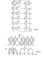
- FIG. 11 an exemplary embodiment of the control set 27 is shown in FIG. 11, with which the ignition pulses T 1 to T 6 of the converter valves 1 to 6 of the inverter WR are generated during operation in the speed range which is above the minimum rotational frequency.
- the signals H 1 to H 3 are in pairs at the inputs 27H.
- these inputs are followed by AND gates 33 to 38.
- the outputs of the AND gates 33 to 38 are connected via pulse amplifiers 60 to 65 directly to the outputs 28, to which the possibly phase-shifted pulses T 1 to T 6 can be assigned in accordance with FIG. 3.
- FIG. 12 shows a possibility with which the mean torque and the torque ripple in the speed range II can be improved.
- the same sizes are plotted in FIG. 12 as in FIG. 8.
- the left part of FIG. 12 represents a commutation as it is obtained after the pulse grid according to FIG. 4.
- FIG. 12 shows the disadvantage already mentioned that with commutation according to the pulse pattern according to FIG. 4, the forced commutation takes place at a moment that is very small. Drops in torque during the period required for the forced commutation can therefore lead to a sharp increase in the torque ripple.
- the right part of FIG. 12 shows how the torque ripple in the speed range II can fundamentally be improved. If the headset 25 is designed for the speed range II so that a pre-ignition of 30 ° el can take place, a torque curve is obtained which has only a slight torque ripple and in which the average torque M m is significantly increased. As the dash-dotted line 66 shows, it amounts to 83% of the peak value of the moment M, compared to 71% according to the dashed line 31 in the left part of the figure.
Abstract
Description
Die Erfindung betrifft ein Verfahren zum Betrieb eines Umrichters mit Gleichstromzwischenkreis, einem Wechselrichter mit Stromrichterventilen in Drehstrombrückenschaltung und einer Drehfeldmaschine als Last, bei dem bei Drehzahlen der Drehfeldmaschine, die größer als eine maschinenbedingte Mindestdrehzahl sind, der Umrichter lastgeführt ist und die Kommutierungsspannung für die Stromrichterventile des Wechselrichters von der Drehfeldmaschine geliefert wird und bei dem bei Drehzahlen, die kleiner als die Mindestdrehzahl sind, die Stromrichterventile des Wechselrichters mit einer Hilfskommutierungseinrichtung kommutiert werden, wobei wenigstens bei Drehzahlen, die größer als die Mindestdrehzahl sind, in einer Drehperiode eine sechsmalige zyklische Kommutierung stattfindet, bei der alternierend in beiden Brückenhälften der Drehstrombrücke jeweils vom Stromrichterventil eines Stromrichterzweigs auf ein nachfolgend stromführendes Stromrichterventil eines Stromrichterzweigs der gleichen Brückenhälfte kommutiert wird.The invention relates to a method for operating a converter with a DC link, an inverter with converter valves in a three-phase bridge circuit and a three-phase machine as a load, in which at speeds of the three-phase machine that are greater than a machine-related minimum speed, the converter is load-guided and the commutation voltage for the converter valves Inverter is supplied by the induction machine and in which at speeds that are lower than the minimum speed, the converter valves of the inverter are commutated with an auxiliary commutation device, wherein at least at speeds that are greater than the minimum speed, six times cyclical commutation takes place in one rotation period, alternating in both bridge halves of the three-phase bridge from the converter valve of a converter branch to a subsequent current-carrying converter valve of a converter branch of the same bridge half is commutated.
Ein solches Verfahren zum Betrieb eines solchen Umrichters, auch-Stromrichtermotor genannt, ist beispielsweise aus der Siemens-Zeitschrift 45 (1971), Seiten 753 bis 757 oder aus der DE-PS 22 46 562 bekannt. Die Taktung des Wechselrichters erfolgt bei diesem Umrichter. lastabhängig, die Kommutierungsblindleistung liefert die Drehfeldmaschine synchroner Bauart.Such a method for operating such a converter, also known as a converter motor, is known, for example, from Siemens magazine 45 (1971), pages 753 to 757 or from DE-PS 22 46 562. The inverter is clocked with this inverter. load-dependent, the commutation reactive power is supplied by the three-phase machine of synchronous design.
Bei diesem Umrichter kann die Blindleistung für die Kommutierung des Motorstromes erst ab einer gewissen, maschinenbedingten Betriebsdrehzahl vom Motor selbst zur Verfügung gestellt werden. Im Drehzahlbereich, der zwischen Null und dieser Mindestdrehzahl liegt, die etwa einem Zehntel der Nenndrehzahl des Stromrichtermotors entspricht, muß daher auf gesondere Kommutierungshilfen, insbesondere beim Anfahren zurückgegriffen werden, mit denen der Bereich kleiner Drehzahlen mit Hilfe einer zusätzlichen Hilfskommutierungseinrichtung bzw. eines zusätzlichen Hilfs- bzw. Anfahrkommutierungsverfahren, durchfahren werden, das entsprechende Umschaltungen bewirkt.With this converter, the reactive power for the commutation of the motor current can only be made available by the motor itself from a certain machine-related operating speed. In the speed range that lies between zero and this minimum speed, which corresponds to approximately one tenth of the nominal speed of the converter motor, special commutation aids, in particular when starting off, must be used, with which the range of low speeds can be used with the aid of an additional auxiliary commutation device or an additional auxiliary or start-up commutation process, which causes corresponding switchovers.
Aus der obengenanten Literaturstelle ist es bekannt, durch einen Steuereingriff in den netzseitigen Gleichrichter oder durch Zünden eines gesteuerten Nebenwegventils, das als Schalter die Zwischenkreisdrossel kurzschließt, den Zwischenkreisstrom jedesmal für eine kurze Zeitspanne zu Null zu machen, in der der Strom zum nächsten Maschinenstrang weitergeschaltet werden soll. Andere Hilfskommutierungseinrichtungen, bei denen der Zwischenkreisstrom vor jeder Kommutierung kurzgeschlossen wird, sind beispielsweise aus der DE-PS 22 46 562 oder der DE-PS 22 46 592 bekannt. Diese Hilfskommutierungseinrichtungen sind auch für größere Anlaufmomente und Leistungen geeignet.From the above-mentioned literature reference it is known to make the intermediate circuit current zero for a short period each time in which the current is switched on to the next machine line by a control intervention in the line-side rectifier or by ignition of a controlled bypass valve which shorts the intermediate circuit choke as a switch should. Other auxiliary commutation devices in which the intermediate circuit current is short-circuited before each commutation are known for example from DE-PS 22 46 562 or DE-PS 22 46 592. These auxiliary commutation devices are also suitable for larger starting torques and powers.
Bei Drehfeldmaschinen hoher Nenndrehzahl oder bei höherpoligen Maschinen erreichen die bekannten Hilfskommutierungsverfahren ihre Grenzfrequenz, bevor die erforderliche Mindestdrehzahl erreicht ist und der nunmehr lastgeführte Wechselrichter den Motorstrom mit Hilfe der Maschinenspannung kommutieren kann. In solchen Fällen müssen andere, aufwendige Anlaufeinrichtungen, beispielsweise Anwurfmotoren oder Anlauftransformatoren eingesetzt werden.In rotating field machines with a high nominal speed or in machines with a higher number of poles, the known auxiliary commutation methods reach their limit frequency before the required minimum speed is reached and the now load-controlled inverter can commutate the motor current with the aid of the machine voltage. In such cases, other complex starting devices, for example starting motors or starting transformers, must be used.
Es besteht die Aufgabe das Verfahren der eingangs genannten Art so weiterzubilden, daß der Drehzahlbereich, in dem zwangskommutiert wird die Grenzfrequenzen herkömmlicher Hilfskommutierungseinrichtungen übersteigen kann.It is the task of developing the method of the type mentioned at the outset such that the speed range in which the forced commutation is carried out can exceed the limit frequencies of conventional auxiliary commutation devices.
Erfindungsgemäß wird diese Aufgabe dadurch gelöst, daß die Drehzahlen, die kleiner als die Mindestdrehzahlen sind, in wenigstens zwei Drehzahlbereiche unterteilt werden, daß in einem ersten, bei der Drehzahl Null beginnenden Drehzahlbereich die sechsmalige Kommutierung pro Drehperiode beibehalten wird und daß in einem sich an den ersten Drehzahlbereich anschließenden zweiten Drehzahlbereich eine dreimalige zyklische Kommutierung pro Drehperiode stattfindet, bei der bei jeder Kommutierung in den Stromrichterzweigen beider Brückenhälften der Drehstrombrückenschaltung gleichzeitig vom Stromrichterventil eines Stromrichterzweiges auf ein nachfolgend stromführendes Stromrichterventil eines anderen Stromrichterzweiges kommutiert wird.According to the invention this object is achieved in that the speeds, which are lower than the minimum speeds, are divided into at least two speed ranges, that in a first speed range starting at zero speed, the six times commutation per rotation period is maintained and that in one the Cyclic commutation takes place three times per rotation period in the first speed range, subsequent second speed range, during which each commutation in the converter branches of both bridge halves of the three-phase bridge circuit is simultaneously commutated from the converter valve of one converter branch to a subsequent current-carrying converter valve of another converter branch.
Bei dem erfindungsgemäßen Verfahren wird im zweiten Drehzahlbereich, der mit der Mindestdrehzahl endet, nicht jede der beim bekannten Verfahren üblichen Kommutierungen, sondern nur jede zweite Kommutierung ausgeführt. Der Drehzahlbereich der Zwangskommutierung wird damit bezüglich der Grenzfrequenz der Hilfskommutierungseinrichtung bzw. des -verfahrens verdoppelt, wobei die Hilfskommutierungseinrichtung unverändert bleibt. Zu betonen ist dabei noch, daß für die Drehzahlen im ersten Drehzahlbereich das volle Drehmoment erhalten bleibt, was insbesondere beim Anfahren für das Losreißmoment wesentlich ist. Im zweiten Drehzahlbereich sinkt zwar der Mittelwert des Drehmomentes ab und es tritt eine Momentenwelligkeit auf, dies stört aber normalerweise in diesem Drehzahlbereich nicht.In the method according to the invention, not every commutation customary in the known method, but only every second commutation, is carried out in the second speed range, which ends with the minimum speed. The speed range of the forced commutation is thus doubled with respect to the cutoff frequency of the auxiliary commutation device or method, the auxiliary commutation device remaining unchanged. It should also be emphasized that the full torque is maintained for the speeds in the first speed range, which is particularly important for the starting torque when starting. In the second speed range, the mean value of the torque drops and a torque ripple occurs, but this does not normally interfere in this speed range.
Vorzugsweise findet in einem sich an den zweiten Drehzahlbereich anschließenden dritten Drehzahlbereich nur eine zweimalige zyklische Kommutierung pro Drehperiode statt, wobei die Drehstrombrücke als Einphasenbrücke betrieben wird, wozu die Stromrichterventile von zwei Stromrichterzweigen mit gemeinsamem Hauptanschluß ungezündet bleiben. Bei dieser vorteilhaften Ausgestaltung des erfindungsgemäßen Verfahrens wird im dritten Drehzahlbereich, der nunmehr mit der erforderlichen Mindestdrehzahl endet, nur noch jede dritte Kommutierung im Wechselrichter ausgeführt. Damit kann der Drehzahlbereich der Zwangskommutierung bezüglich der Grenzfrequenz jedes der herkömmlichen Hilfskommutierungsverfahren verdreifacht werden. Der Mittelwert des Drehmomentes in diesem dritten Drehzahlbereich sinkt nur noch geringfügig gegenüber dem Drehmomentmittel im zweiten Drehzahlbereich ab und auch die Momentenwelligkeit erhöht sich nur unwesentlich.Preferably, in a third speed range adjoining the second speed range, there is only two cyclic commutation per rotation period, the three-phase bridge being operated as a single-phase bridge, for which purpose the converter valves of two converter branches with a common main connection remain unignited. In this advantageous embodiment of the method according to the invention, in the third speed range, which now ends with the required minimum speed, only every third commutation is carried out in the inverter. The speed range of the forced commutation with respect to the cutoff frequency of each of the conventional auxiliary commutation methods can thus be tripled. The mean value of the torque in this third speed range drops only slightly compared to the torque mean in the second speed range and the torque ripple also increases only insignificantly.
Im folgenden wird das erfindungsgemäße Verfahren beispielhaft anhand der Figuren 1 bis 12 näher erläutert.The method according to the invention is explained in more detail below with reference to FIGS. 1 to 12.
Figur 1 zeigt die Schaltung eines Stromrichtermotors. Ein gesteuerter Wechselrichter WR ist aus steuerbaren Stromrichterventilen 1 bis 6 in Drehstrombrückenschaltung aufgebaut. Die Stromrichterzweige 1a bis 3a und 4a bis 6a jeder Brückenhälfte WR1 und WR2 sind über ihre gemeinsamen Hauptanschlüsse 7 bis 9 mit der dreiphasigen Wicklung einer Synchronmaschine 10 verbunden, an der im Betrieb die Maschinenspannung u, v und w ansteht. Der Wechselrichter WR wird aus einem Drehstromnetz R, S, T über einen gesteuerten Gleichrichter 11 und einen Gleichstromzwischenkreis 12 mit Zwischenkreis- bzw. Glättungsinduktivität 13-gespeist. Im Ausführungsbeispiel ist der Gleichrichter 11 aus sechs steuerbaren Stromrichterventilen 11a bis 11f in Drehstrombrückenschaltung aufgebaut. Die steuerbaren Stromrichterventile 1 bis 6 des Wechselrichters WR und die steuerbaren Stromrichterventile 11a bis 11f des Gleichrichters 11 können beispielsweise Thyristoren sein.Figure 1 shows the circuit of a converter motor. A controlled inverter WR is made up of
Mit dem Läufer des Drehstromsynchronmotors 1 ist ein Tachodynamo 14 und ein beispielsweise permanentmagnetischer oder mit Hallgeneratoren bestückter Rotorlagegeber 15 mechanisch gekoppelt. Die Signale des Läuferstellungsgebers 15 sind einem Umschalter 16 zugeführt. Die den Drehzahlistwert repräsentierenden Signale des Tachodynamos 14 werden in einer Addierstufe 17 mit einem Drehzahlsollwert verglichen, der der Addierstufe 17 über einen Eingang 18 zugeführt ist. Die erhaltene Regelabweichung liegt an einem Drehzahlregler 19, dessen Ausgang zum Vergleich seiner Signalspannung mit den Signalen eines Stromwandlers 20 einer zweiten Addierstufe 21 zugeführt ist. Der Stromwandler 20 ist in der Drehstromspeiseleitung angeordnet. Der Addierstufe 21 ist ein Stromregler 22 nachgeschaltet, von dem über Leitungen 23 die Stromrichterventile 11a bis 11f des Gleichrichters 11 angesteuert werden. Bezüglich dieser Ansteuerung des Gleichrichters 11 wird auf die obengenannte Literaturstelle verwiesen.With the rotor of the three-phase
Der mit dem Tachodynamo 14 erfaßte Drehzahlistwert ist außerdem noch dem Eingang 24a eines Grenzwertmelders 24 zugeführt. Der Grenzwertmelder 24 erzeugt in einem ersten Drehzahlbereich I, der mit der Drehzahl Null beginnt, ein Signal A, in einem zweiten Drehzahlbereich II, der sich an den ersten-Drehzahlbereich I anschließt, ein Signal B und in einem dritten Drehzahlbereich II, der mit der maschinenbedingten Mindestdrehzahl endet, ein Signal C. Beim Überschreiten der Mindestdrehzahl erzeugt der Grenzwertmelder schließlich ein Signal D. Diese Signale A bis D stehen an den mit gleichen Großbuchstaben versehenen Ausgängen 24A bis 24D des Grenzwertmelders 24 an. Die Ausgänge 24A bis 24C des Grenzwertmelders 24 sind mit Eingängen 25A bis 25C eines ersten Steuersatzes 25 verbunden, von dem über Leitungen 26 die steuerbaren Stromrichterventile 1 bis 6 des Wechselrichters WR angesteuert werden. Der Ausgang 24D des Grenzwertmelders 24 ist mit dem Betätigungseingang 16a des Umschalters 16 verbunden. Über den Ruhekontakt des Umschalters 16 ist der Ausgang des Rotorlagegebers 15 mit einem Eingang 25H des Steuersatzes 25 verknüpft. Der Arbeitskontakt des Umschalters 16 ist mit einem Eingang 27a eines zweiten Steuersatzes 27 verbunden. Überschreitet daher der mit dem Tachodynamo 14 erfaßte Drehzahlistwert die vorgegebene Mindestdrehzahl, so wird von dem Signal D der Ausgang des Rotorlagegebers 15 vom Eingang 25H des Steuersatzes 25 auf den Eingang 27H des Steuersatzes 27 umgeschaltet. Auch vom Steuersatz 27 werden über Leitungen 28 die steuerbaren Stromrichterventile 1 bis 6 des Wechselrichters WR angesteuert. Auf den Aufbau der beiden Steuersätze 25 und 27 wird im folgenden noch näher eingegangen.The actual speed value recorded with the
Als Hilfskommutierungseinrichtung ist beim Stromrichtermotor nach Figur 1 beispielhaft ein Schalter 29 vorgesehen, der in bekannter Weise die Zwischenkreisinduktivität 13 überbrückt und im geschlossenen Zustand kurzschließt. Der Betätigungseingang 29a des Schalters 29 ist mit einem Ausgang 25a des ersten Steuersatzes 25 verbunden. Bei Drehzahlen, die kleiner als die maschinenbedingte Mindestdrehzahl ist, wird der Schalter 29 über ein kurzzeitig am Betätigungseingang 29a anstehendes Signal geschlossen, womit in bekannter Weise für jede Kommutierung die Zwischenkreisdrossel kurzgeschlossen und damit der Zwischenkreisstrom für jede Kommutierung kurzzeitig zu Null gemacht wird. Es ist zu betonen, daß anstelle der beispielhaft angeführten Hilfskommutierungseinrichtung 29 jedes andere Hilfskommutierungsverfahren nach dem erfindungsgemäßen Verfahren betrieben werden kann.A
Im folgenden wird das erfindungsgemäße Verfahren zum Betrieb eines Stromrichtermotors gemäß Figur 1 bei Drehzahlen, die kleiner als die Mindestdrehzahl sind, anhand der Figuren 2 bis 6 näher erläutert, in denen Impulsdiagramme bezogen auf die Drehperiode des Synchronmotors 10 in Grad el aufgetragen sind. Figur 1 zeigt die vom Rotorlagegeber 15 erzeugten Signale H1 bis H32 deren Länge jeweils 180° el beträgt und die um 120° el gegeneinander verschoben sind. Zu jedem Signal H1 bis H3 wird in einem in Figur 1 nicht dargestellten Invertierglied das invertierte Signal H1 bis H3 erzeugt. Die Signale H1 bis H3 und H1 bis H3 werden über den Umschalter 16 dem Eingang 25H des Steuersatzes 25 zugeführt, solange die Drehzahl des Motors 10 kleiner als seine Mindestdrehzahl ist. In dem Drehzahlbereich I, der mit dem Signal A des Grenzwertmelders 24 bestimmt ist, werden durch die folgenden logischen Verknüpfungsgleichungen![]()
![]()
![]()
![]()
![]()
![]()


![]()
![]()
![]()
![]()
![]()
![]()
Überschreitet schließlich der von dem Tachodynamo 14 abgegebene Drehzahlistwert den Drehzahlbereich II, so steht im Drehzahlbereich III nur am Ausgang 24C des Grenzwertmelders 24 das Signal C an. Mit diesem Signal C wird im Steuersatz 25 eine logische Verknüpfung,beispielsweise gemäß dem folgenden Gleichungssystem erhalten:![]()
![]()
![]()
![]()
Das damit erzeugte und in Figur 6 gezeigte Impulsraster verdeutlicht, daß im Drehzahlbereich III die Drehstrombrücke WR als Einphsenbrücke betrieben wird, wozu im gesamten Drehzahlbereich III die Stromrichterventile von zwei Stromrichterzweigen mit gemeinsamem Hauptanschluß, gemäß Figur 6 beispielsweise die Stromrichterventile 2 und 5 mit dem gemeinsamen Hauptanschluß 8 ungezündet bleiben. Damit erhält man bei unveränderter Hilfskommutierungseinrichtung 29 einen Drehzahlbereich für die Zwangskommutierung, der das Dreifache der . Grenzfrequenz des Hilfskommutierungsverfahrens ist, die man im Drehzahlbereich I erreicht. Nach Überschreiten der maschinenbedingten Mindestfrequenz steht nur noch am Ausgang 24D des Grenzwertmelders 24 das Signal D an. Mit diesem Signal D werden im Umschalter 16 die Signale H1 bis H3 des Rotorlagegebers 15 dem Steuersatz 27 über seinen Eingang 27H aufgeschaltet, womit der Steuersatz 25 und damit-die Hilfskommutierungseinrichtung 29 abgeschaltet werden. Im Steuersatz 27 wird lastgetaktet entsprechend den Verknüpfungsgleichungen, die im Zusammenhang mit Figur 3 angegeben sind, ein Impulsraster T1 bis T6 erhalten, das der Figur 3 entspricht, wobei die Kommutierungsblindleistung nunmehr vom Synchronmotor 10 zur Verfügung gestellt wird.The pulse grid thus generated and shown in FIG. 6 illustrates that the three-phase bridge WR is operated as a single-phase bridge in the speed range III, for which purpose the converter valves of two converter branches with a common main connection in the entire speed range III, for example the
In den Figuren 7 bis 9 ist für die Drehzahlbereiche I bis III jeweils der Verlauf der Maschinenspannungen u, v und w an der dreiphasigen Wicklung des Synchronmotors 10 und der Momentverlauf M bezogen auf die Drehperiode in °el aufgezeichnet.In FIGS. 7 to 9, the course of the machine voltages u, v and w on the three-phase winding of the
Figur 7 zeigt die normale Kommutierung im Drehzahlbereich I. Das damit erhaltene mittlere Drehmoment Mm des Synchronmotors 10 beträgt 95 % des Spitzenwertes M, wie in Figur 7 mit der strichpunktierten Linie 30 gezeigt ist.FIG. 7 shows normal commutation in the speed range I. The mean torque M m of the
Figur 8 zeigt den Verlauf der Maschinenspannungen u, v und w im Drehzahlbereich II und den zugehörigen Momentenverlauf M, wobei der Figur 8 eine zyklische Kommutierung in beiden Brückenzweigen WR1 und WR2 im Abstand von jeweils 120° el gemäß Figur 5 zugrundegelegt ist. Die gestrichelte Linie 31 zeigt, daß das mittlere Drehmoment Mm gegenüber dem im Drehzahlbereich I erhaltenen Drehmoment abgesunken ist und 71 % des Spitzenwertes M beträgt. Auch die Welligkeit des Momentenverlaufs ist angewachsen. In den meisten Anwendungsfällen spielt weder der Abfall des mittleren Drehmomentes, noch die größere Momentenwelligkeit eine Rolle. Dies gilt insbesondere falls der Stromrichter nach Figur 1 zum Antrieb von Lüftern, Zentrifugen, Kompressoren usw. benützt wird. Der Figur 8 ist weiterhin der Vorteil des Kommutierungsverfahrens gemäß Figur 5 im Vergleich mit dem Kommutierungsverfahren gemäß Figur 4 zu entnehmen. Bei den Kommutierungsverfahren gemäß Figur 5 wird jeweils bei einem Drehmoment kommutiert, das wesentlich größer als Null ist. Kurzfristige, durch die Zwangskommutierung bedingte Momenteinbrüche, die aufgrund einer Totzeit gegebenenfalls sogar zu einem negativen Moment führen können, wirken sich daher nicht aus, im Gegensatz zum Kommutierungsverfahren nach Figur 4, wo, wie später noch gezeigt wird, die Zwangskommutierung bei einem Moment M eingeleitet wird, das in der Nähe von Null liegt.FIG. 8 shows the profile of the machine voltages u, v and w in the speed range II and the associated torque profile M, FIG. 8 being based on cyclic commutation in both bridge branches WR1 and WR2 at intervals of 120 ° el in accordance with FIG. 5. The
Figur 9 zeigt den Verlauf von u, v und w und den Momentenverlauf M im Drehzahlbereich III, in dem eine Kommutierung gemäß einer Einphasenbrücke nur jeweils nach 180° el stattfindet. Die gestrichelte Linie 32, die wiederum die Größe des mittleren Drehmomentes Mm angibt, zeigt, daß das mittlere Drehmoment Mm im Drehzahlbereich III gegenüber dem Drehzahlbereich II nur noch geringfügig abgesunken ist. Das mittlere Drehmoment Mm beträgt 64 % des maximalen Drehmomentes M. Die Momentenwelligkeit hat erneut zugenommen, wie oben jedoch bereits betont, spielt dies in den meisten Anwendungsfällen keine wesentliche Rolle.FIG. 9 shows the profile of u, v and w and the torque profile M in the speed range III, in which commutation according to a single-phase bridge only takes place after 180 ° el. The dashed line 32, which in turn indicates the size of the average torque M m , shows that the average torque M m in the speed range III has decreased only slightly compared to the speed range II. The average torque M m is 64% of the maximum torque M. The torque ripple has increased again, but as already emphasized above, this does not play a significant role in most applications.
Figur 10 zeigt ein Ausführungsbeispiel für den Steuersatz 25, mit dem die Stromrichterventile 1 bis 6 des Wechselrichters WR bei Drehzahlen angesteuert werden, die in den Drehzahlbereichen I bis III liegen, wobei gleichzeitig zur Einleitung jeder Kommutierung der Schalter der Hilfskommutierungseinrichtung 29 geschlossen wird. An den Eingängen 25H stehen paarweise die Signale H1 bis H3 an, wie sie mit den Verknüpfungsgleichungen im Zusammenhang mit Figur 3 angegeben sind. Die jeweils einander zugeordneten Signale H1 bis H3 sind in Figur 10 eingezeichnet. Jeweils zwei einander zugeordneten Eingängen 25H ist ein logisches Verknüpfungsglied mit konjunktiver Verknüpfung 33 bis 38 nachgeschaltet. Der Ausgang jedes UND-Gliedes 33 bis 38 ist jeweils dem ersten Eingang eines weiteren UND-Gliedes 39 bis 44 zugeführt. Der zweite Eingang jedes UND-Gliedes 39 ist mit dem Eingang 25A verbunden, an dem das Signal A des Grenzwertmelders 24 ansteht. Dem Ausgang jedes UND-Gliedes 39 bis 44 ist ein Eingang jeweils eines logischen Verknüpfungsgliedes mit diskonjunktiver Verknüpfung 45 bis 50 nachgeschaltet.FIG. 10 shows an exemplary embodiment of the control set 25, with which the
Der zweite Eingang der ODER-Glieder 45 und 50 ist mit dem Ausgang eines UND-Gliedes 51 verbunden, dessen erstem Eingang der Ausgang des UND-Gliedes 33 zugeführt ist. Der zweite Eingang jedes ODER-Gliedes 46 und 48 ist mit dem Ausgang eines UND-Gliedes 51 verbunden, dessen erster Eingang mit dem Ausgang des UND-Gliedes 34 verknüpft ist. Ebenso sind die zweiten Eingänge der ODER-Glieder 47 und 49 mit dem Ausgang eines UND-Gliedes 53 verbunden, an dessen ersten Eingang der Ausgang des UND-Gliedes 35 liegt. Die zweiten Eingänge der UND-Glieder 51 bis 53 sind mit dem Eingang 25B verbunden, an dem das Signal B ansteht, das den Drehzahlbereich II kennzeichnet. Ein logisches "1"-Signal am Eingang 25B führt zu einer logischen Verknüpfung, wie sie im Zusammenhang mit Figur 5 bereits erläutert wurde. Der Ausgang jedes der.ODER-Glieder 45, 47, 48 und 50 ist dem ersten Eingang jeweils eines ODER-Gliedes 54 bis 57 zugeführt. Der zweite Eingang jedes ODER-Gliedes 54 und 57 ist mit dem Ausgang eines UND-Gliedes 58 verbunden, dessen erstem Eingang das Signal H1 des Rotorlagegebers 15 zugeführt ist. Der zweite Eingang jedes ODER-Gliedes 55 und 56 ist mit dem Ausgang eines UND-Gliedes 59 verbunden, dessen invertierendem Eingang ebenfalls das Rotorlagesignal H1 zugeführt ist. Die zweiten Eingänge der UND-Glieder 58 und 59 sind mit dem Eingang 25C verbunden, an dem das Signal C des Grenzwertmelders 24 im Drehzahlbereich III ansteht. Ist das Signal C ein logisches "1"-Signal, so erhält man eine logische Verknüpfung, wie-sie im Zusammenhang mit Figur 6 erläutert wurde. Den Ausgängen der ODER-Glieder 54, 46, 55, 56, 49 und 57 ist jeweils ein Impulsverstärker 60 bis 65 nachgeschaltet, der jeweils mit einem der Ausgänge 26 verbunden ist. Die über die Ausgänge 26 erzeugten Impulse T1 bis T6 der Impulsraster gemäß Figur 3 bis 6 sind an den betreffenden Ausgängen angegeben. Mit dem in Figur 10 erläuterten Steuersatz 25 erhält man gemäß den logischen Verknüpfungen, die im Zusammenhang mit Figur 6 angegeben sind, folgendes logisches Schema für die Drehzahlbereiche I bis III
Zur Vervollständigung ist in Figur 11 ein Ausführungsbeispiel des Steuersatzes 27 gezeigt, mit dem die Zündimpulse T1 bis T6 der Stromrichterventile 1 bis 6 des Wechselrichters WR beim Betrieb im Drehzahlbereich erzeugt werden, der oberhalb der Mihdestdrehfrequenz liegt. Entsprechend den im Zusammenhang mit Figur 3 angegebenen logischen Verknüpfungen liegen die Signale H1 bis H3 paarweise an den Eingängen 27H. Wie im Ausführungsbeispiel nach Figur 10 sind diesen Eingängen UND-Glieder 33 bis 38 nachgeschaltet. Die Ausgänge der UND-Glieder 33 bis 38 sind über Impulsverstärker 60 bis 65 direkt mit den Ausgängen 28 verbunden, denen die gegebenenfalls phasenverschobenen Impulse T1 bis T6 entsprechend Figur 3 zuzuordnen sind.For completion, an exemplary embodiment of the control set 27 is shown in FIG. 11, with which the ignition pulses T 1 to T 6 of the
Figur 12 zeigt eine Möglichkeit, mit der das mittlere Moment und die Momentenwelligkeit im Drehzahlbereich II verbessert werden kann. Dabei sind in Figur 12 die gleichen Größen wie in Figur 8 aufgetragen. Der linke Teil der Figur 12 repräsentiert eine Kommutierung, wie sie nach dem Impulsraster gemäß Figur 4 erhalten wird. Der Figur 12 ist der bereits erwähnte Nachteil zu entnehmen, daß bei einer Kommutierung entsprechend dem Impulsraster nach Figur 4 die Zwangskommutierung bei einem Moment erfolgt, das sehr klein ist. Momenteneinbrüche während des Zeitraums, der für die Zwangskommutierung erforderlich ist, können daher zu einer starken Vergrößerung der Momentenwelligkeit führen.FIG. 12 shows a possibility with which the mean torque and the torque ripple in the speed range II can be improved. The same sizes are plotted in FIG. 12 as in FIG. 8. The left part of FIG. 12 represents a commutation as it is obtained after the pulse grid according to FIG. 4. FIG. 12 shows the disadvantage already mentioned that with commutation according to the pulse pattern according to FIG. 4, the forced commutation takes place at a moment that is very small. Drops in torque during the period required for the forced commutation can therefore lead to a sharp increase in the torque ripple.
Im rechten Teil der Figur 12 ist gezeigt, wie sich die Momentenwelligkeit im Drehzahlbereich II grundsätzlich verbessern läßt. Wird für den Drehzahlbereich II der Steuersatz 25 so ausgebildet, daß eine Vorzündung von 30° el erfolgen kann, so erhält man einen Drehmomentenverlauf, der nur eine geringe Momentenwelligkeit aufweist und bei dem das mittlere Drehmoment Mm wesentlich vergrößert ist. Es beträgt, wie die strichpunktierte Linie 66 zeigt, 83 % des Spitzenwertes des Momentes M, im Vergleich zu 71 % gemäß der gestrichelten Linie 31 im linken Figurenteil.The right part of FIG. 12 shows how the torque ripple in the speed range II can fundamentally be improved. If the
Claims (2)
Priority Applications (1)
| Application Number | Priority Date | Filing Date | Title |
|---|---|---|---|
| AT81106171T ATE10407T1 (en) | 1980-08-12 | 1981-08-06 | PROCEDURE FOR OPERATING A CONVERTER WITH A DC LINK FOR SUPPLYING A THREE-PHASE MACHINE. |
Applications Claiming Priority (2)
| Application Number | Priority Date | Filing Date | Title |
|---|---|---|---|
| DE3030465A DE3030465C2 (en) | 1980-08-12 | 1980-08-12 | Method for operating a converter with a direct current intermediate circuit for supplying a three-phase machine |
| DE3030465 | 1980-08-12 |
Publications (3)
| Publication Number | Publication Date |
|---|---|
| EP0045951A2 true EP0045951A2 (en) | 1982-02-17 |
| EP0045951A3 EP0045951A3 (en) | 1982-02-24 |
| EP0045951B1 EP0045951B1 (en) | 1984-11-21 |
Family
ID=6109445
Family Applications (1)
| Application Number | Title | Priority Date | Filing Date |
|---|---|---|---|
| EP81106171A Expired EP0045951B1 (en) | 1980-08-12 | 1981-08-06 | Process for operating an inverter with an intermediate dc link circuit supplying an electric synchronous motor |
Country Status (6)
| Country | Link |
|---|---|
| US (1) | US4486698A (en) |
| EP (1) | EP0045951B1 (en) |
| JP (1) | JPS5762792A (en) |
| AT (1) | ATE10407T1 (en) |
| CA (1) | CA1176703A (en) |
| DE (2) | DE3030465C2 (en) |
Cited By (2)
| Publication number | Priority date | Publication date | Assignee | Title |
|---|---|---|---|---|
| EP0144161A2 (en) * | 1983-11-05 | 1985-06-12 | Kabushiki Kaisha Toshiba | Control system for an ac motor |
| CN103357197A (en) * | 2013-07-01 | 2013-10-23 | 内乡县乌克生物化学制品有限公司 | Equipment for continuously and automatically separating mutually insoluble liquid mixture |
Families Citing this family (8)
| Publication number | Priority date | Publication date | Assignee | Title |
|---|---|---|---|---|
| JPS59110392A (en) * | 1982-12-14 | 1984-06-26 | Toyo Electric Mfg Co Ltd | Speed control circuit for commutatorless motor |
| JPS59166700U (en) * | 1983-04-22 | 1984-11-08 | 永田醸造株式会社 | Automatic care device for rotary automatic koji making equipment |
| DE3427841A1 (en) * | 1984-07-27 | 1986-02-06 | Siemens AG, 1000 Berlin und 8000 München | METHOD AND DEVICE FOR THE OPERATION OF AN INTERMEDIATE CONVERTER WITH CURRENT LIMIT |
| US4701839A (en) * | 1984-11-09 | 1987-10-20 | International Cybernetic Corporation | Sampled data servo control system with field orientation |
| US5402054A (en) * | 1989-09-11 | 1995-03-28 | Boral Johns Perry Industries Pty. Ltd. | Variable speed AC drive control |
| US5483140A (en) * | 1993-10-01 | 1996-01-09 | Wisconsin Alumni Research Foundation | Thyristor based DC link current source power conversion system for motor driven operation |
| US7081735B1 (en) * | 2003-09-16 | 2006-07-25 | Rockwell Automation Technologies, Inc. | System and method for bypassing a motor drive |
| US7345449B2 (en) * | 2005-08-29 | 2008-03-18 | Benshaw, Inc. | Method of rotating a polyphase motor at less than rated speed |
Citations (2)
| Publication number | Priority date | Publication date | Assignee | Title |
|---|---|---|---|---|
| US3872364A (en) * | 1972-09-22 | 1975-03-18 | Siemens Ag | Extinguishing arrangement for the inverters of an electric motor |
| US3887862A (en) * | 1972-09-22 | 1975-06-03 | Siemens Ag | Auxiliary extinguishing arrangement for the inverters in an intermediate link converter |
Family Cites Families (3)
| Publication number | Priority date | Publication date | Assignee | Title |
|---|---|---|---|---|
| JPS5953795B2 (en) * | 1978-02-03 | 1984-12-26 | 株式会社日立製作所 | Thyristor motor control device |
| US4230979A (en) * | 1978-04-10 | 1980-10-28 | General Electric Company | Controlled current inverter and motor control system |
| US4295085A (en) * | 1979-05-25 | 1981-10-13 | General Electric Company | Phase lock loop commutation position control and method |
-
1980
- 1980-08-12 DE DE3030465A patent/DE3030465C2/en not_active Expired
-
1981
- 1981-08-05 US US06/290,313 patent/US4486698A/en not_active Expired - Fee Related
- 1981-08-06 EP EP81106171A patent/EP0045951B1/en not_active Expired
- 1981-08-06 AT AT81106171T patent/ATE10407T1/en not_active IP Right Cessation
- 1981-08-06 DE DE8181106171T patent/DE3167312D1/en not_active Expired
- 1981-08-11 CA CA000383654A patent/CA1176703A/en not_active Expired
- 1981-08-11 JP JP56125846A patent/JPS5762792A/en active Granted
Patent Citations (2)
| Publication number | Priority date | Publication date | Assignee | Title |
|---|---|---|---|---|
| US3872364A (en) * | 1972-09-22 | 1975-03-18 | Siemens Ag | Extinguishing arrangement for the inverters of an electric motor |
| US3887862A (en) * | 1972-09-22 | 1975-06-03 | Siemens Ag | Auxiliary extinguishing arrangement for the inverters in an intermediate link converter |
Non-Patent Citations (1)
| Title |
|---|
| Technische Mitteilungen AEG-Telefunken, Band 67, Nr. 1, 1977, seiten 20-25 Berlin, DE. R. SAUPE et al.: "Maschinengefuehrter Umrichter zur Drehzahlregelung von Synchronmaschinen" *seite 20, rechte spalte, zeile 53 - seite 21, rechte spalte, zeile 32; abbildungen 1-3* * |
Cited By (3)
| Publication number | Priority date | Publication date | Assignee | Title |
|---|---|---|---|---|
| EP0144161A2 (en) * | 1983-11-05 | 1985-06-12 | Kabushiki Kaisha Toshiba | Control system for an ac motor |
| EP0144161A3 (en) * | 1983-11-05 | 1988-07-06 | Kabushiki Kaisha Toshiba | Control system for an ac motor |
| CN103357197A (en) * | 2013-07-01 | 2013-10-23 | 内乡县乌克生物化学制品有限公司 | Equipment for continuously and automatically separating mutually insoluble liquid mixture |
Also Published As
| Publication number | Publication date |
|---|---|
| ATE10407T1 (en) | 1984-12-15 |
| JPS6243437B2 (en) | 1987-09-14 |
| JPS5762792A (en) | 1982-04-15 |
| DE3030465A1 (en) | 1982-03-04 |
| DE3167312D1 (en) | 1985-01-03 |
| EP0045951A3 (en) | 1982-02-24 |
| CA1176703A (en) | 1984-10-23 |
| US4486698A (en) | 1984-12-04 |
| DE3030465C2 (en) | 1982-06-03 |
| EP0045951B1 (en) | 1984-11-21 |
Similar Documents
| Publication | Publication Date | Title |
|---|---|---|
| DE3149017C2 (en) | Drive system with an electric motor | |
| DE3006034A1 (en) | START-UP SYSTEM FOR A BRUSHLESS MOTOR | |
| DE2508546B2 (en) | Brushless DC motor | |
| EP0045951B1 (en) | Process for operating an inverter with an intermediate dc link circuit supplying an electric synchronous motor | |
| DE10234594B4 (en) | Generator / engine system and method of operating this generator / engine system | |
| DE2425362A1 (en) | SPEED-CHANGEABLE ELECTRIC DRIVE DEVICE WITH USED BRAKING POSSIBILITY | |
| WO2013113540A2 (en) | Elective control of an alternating current motor or direct current motor | |
| DE3015108A1 (en) | INVERTER SYSTEM AND METHOD AND METHOD FOR SUPPLYING AN AC MOTOR | |
| DE102008023210A1 (en) | Method for starting a system for generating electrical energy | |
| DE3816449A1 (en) | METHOD AND DEVICE FOR BRAKING A KAEFIG RUNNER MOTOR | |
| WO2017121611A1 (en) | Vacuum pump drive having two frequency converters | |
| DE2752126B2 (en) | Control method for AC-DC thyristor converters | |
| DE2556582C2 (en) | Method and apparatus for operating a polyphase AC motor | |
| DE2842391A1 (en) | Speed changeover circuit for three=phase motor - has triac switches in and between supply lines to motor to change mode | |
| EP0613236B1 (en) | Device for operating a compressor electromotor drive of a refrigerating unit for electrical installation cabinets | |
| DE2950907A1 (en) | DRIVE ARRANGEMENT WITH A FREQUENCY CONVERTER FEEDED TWO-PHASE SYNCHRONOUS MOTOR | |
| EP0253265B1 (en) | Process for putting into operation a converter control from a current-source inverter with phase-sequence quenching | |
| CH627316A5 (en) | ||
| AT414290B (en) | Converter arrangement | |
| DE2247867C3 (en) | Circuit arrangement for speed control of an AC motor | |
| DE2237233C3 (en) | Circuit arrangement for a induction machine | |
| DE3030810C2 (en) | DC link converter for supplying a three-phase machine | |
| WO2020058445A1 (en) | Control device for an inverter, inverter for a vehicle, vehicle, and method for operating an inverter | |
| DD206288B1 (en) | METHOD FOR ASSEMBLING A DRIVE WITH A VOLTAGE CHARGER | |
| DE2247867A1 (en) | THYRISTOR MOTOR |
Legal Events
| Date | Code | Title | Description |
|---|---|---|---|
| PUAI | Public reference made under article 153(3) epc to a published international application that has entered the european phase |
Free format text: ORIGINAL CODE: 0009012 |
|
| PUAL | Search report despatched |
Free format text: ORIGINAL CODE: 0009013 |
|
| 17P | Request for examination filed |
Effective date: 19811028 |
|
| AK | Designated contracting states |
Designated state(s): AT CH DE FR GB IT NL SE |
|
| AK | Designated contracting states |
Designated state(s): AT CH DE FR GB IT NL SE |
|
| ITF | It: translation for a ep patent filed |
Owner name: STUDIO JAUMANN |
|
| GRAA | (expected) grant |
Free format text: ORIGINAL CODE: 0009210 |
|
| AK | Designated contracting states |
Designated state(s): AT CH DE FR GB IT LI NL SE |
|
| REF | Corresponds to: |
Ref document number: 10407 Country of ref document: AT Date of ref document: 19841215 Kind code of ref document: T |
|
| REF | Corresponds to: |
Ref document number: 3167312 Country of ref document: DE Date of ref document: 19850103 |
|
| ET | Fr: translation filed | ||
| PGFP | Annual fee paid to national office [announced via postgrant information from national office to epo] |
Ref country code: AT Payment date: 19850731 Year of fee payment: 5 |
|
| PGFP | Annual fee paid to national office [announced via postgrant information from national office to epo] |
Ref country code: NL Payment date: 19850831 Year of fee payment: 5 |
|
| PLBE | No opposition filed within time limit |
Free format text: ORIGINAL CODE: 0009261 |
|
| STAA | Information on the status of an ep patent application or granted ep patent |
Free format text: STATUS: NO OPPOSITION FILED WITHIN TIME LIMIT |
|
| 26N | No opposition filed | ||
| PG25 | Lapsed in a contracting state [announced via postgrant information from national office to epo] |
Ref country code: AT Effective date: 19860806 |
|
| PG25 | Lapsed in a contracting state [announced via postgrant information from national office to epo] |
Ref country code: SE Effective date: 19860807 |
|
| PG25 | Lapsed in a contracting state [announced via postgrant information from national office to epo] |
Ref country code: LI Effective date: 19860831 Ref country code: CH Effective date: 19860831 |
|
| PG25 | Lapsed in a contracting state [announced via postgrant information from national office to epo] |
Ref country code: NL Effective date: 19870301 |
|
| NLV4 | Nl: lapsed or anulled due to non-payment of the annual fee | ||
| GBPC | Gb: european patent ceased through non-payment of renewal fee | ||
| PG25 | Lapsed in a contracting state [announced via postgrant information from national office to epo] |
Ref country code: FR Free format text: LAPSE BECAUSE OF NON-PAYMENT OF DUE FEES Effective date: 19870430 |
|
| REG | Reference to a national code |
Ref country code: CH Ref legal event code: PL |
|
| REG | Reference to a national code |
Ref country code: FR Ref legal event code: ST |
|
| PG25 | Lapsed in a contracting state [announced via postgrant information from national office to epo] |
Ref country code: GB Effective date: 19881118 |
|
| PGFP | Annual fee paid to national office [announced via postgrant information from national office to epo] |
Ref country code: DE Payment date: 19901025 Year of fee payment: 10 |
|
| PG25 | Lapsed in a contracting state [announced via postgrant information from national office to epo] |
Ref country code: DE Effective date: 19920501 |
|
| EUG | Se: european patent has lapsed |
Ref document number: 81106171.2 Effective date: 19870812 |