EP0044468A2 - Heat-insulated tubing element and tubing system comprising such tubing elements as well as methods for manufacturing of said tubing element and said tubing system - Google Patents
Heat-insulated tubing element and tubing system comprising such tubing elements as well as methods for manufacturing of said tubing element and said tubing system Download PDFInfo
- Publication number
- EP0044468A2 EP0044468A2 EP81105317A EP81105317A EP0044468A2 EP 0044468 A2 EP0044468 A2 EP 0044468A2 EP 81105317 A EP81105317 A EP 81105317A EP 81105317 A EP81105317 A EP 81105317A EP 0044468 A2 EP0044468 A2 EP 0044468A2
- Authority
- EP
- European Patent Office
- Prior art keywords
- pipe
- heat
- elements
- useful
- layer
- Prior art date
- Legal status (The legal status is an assumption and is not a legal conclusion. Google has not performed a legal analysis and makes no representation as to the accuracy of the status listed.)
- Granted
Links
Images


Classifications
-
- F—MECHANICAL ENGINEERING; LIGHTING; HEATING; WEAPONS; BLASTING
- F16—ENGINEERING ELEMENTS AND UNITS; GENERAL MEASURES FOR PRODUCING AND MAINTAINING EFFECTIVE FUNCTIONING OF MACHINES OR INSTALLATIONS; THERMAL INSULATION IN GENERAL
- F16L—PIPES; JOINTS OR FITTINGS FOR PIPES; SUPPORTS FOR PIPES, CABLES OR PROTECTIVE TUBING; MEANS FOR THERMAL INSULATION IN GENERAL
- F16L59/00—Thermal insulation in general
- F16L59/12—Arrangements for supporting insulation from the wall or body insulated, e.g. by means of spacers between pipe and heat-insulating material; Arrangements specially adapted for supporting insulated bodies
- F16L59/123—Anchoring devices; Fixing arrangements for preventing the relative longitudinal displacement of an inner pipe with respect to an outer pipe, e.g. stress cones
-
- F—MECHANICAL ENGINEERING; LIGHTING; HEATING; WEAPONS; BLASTING
- F16—ENGINEERING ELEMENTS AND UNITS; GENERAL MEASURES FOR PRODUCING AND MAINTAINING EFFECTIVE FUNCTIONING OF MACHINES OR INSTALLATIONS; THERMAL INSULATION IN GENERAL
- F16L—PIPES; JOINTS OR FITTINGS FOR PIPES; SUPPORTS FOR PIPES, CABLES OR PROTECTIVE TUBING; MEANS FOR THERMAL INSULATION IN GENERAL
- F16L59/00—Thermal insulation in general
- F16L59/02—Shape or form of insulating materials, with or without coverings integral with the insulating materials
-
- F—MECHANICAL ENGINEERING; LIGHTING; HEATING; WEAPONS; BLASTING
- F16—ENGINEERING ELEMENTS AND UNITS; GENERAL MEASURES FOR PRODUCING AND MAINTAINING EFFECTIVE FUNCTIONING OF MACHINES OR INSTALLATIONS; THERMAL INSULATION IN GENERAL
- F16L—PIPES; JOINTS OR FITTINGS FOR PIPES; SUPPORTS FOR PIPES, CABLES OR PROTECTIVE TUBING; MEANS FOR THERMAL INSULATION IN GENERAL
- F16L59/00—Thermal insulation in general
- F16L59/14—Arrangements for the insulation of pipes or pipe systems
- F16L59/16—Arrangements specially adapted to local requirements at flanges, junctions, valves or the like
- F16L59/18—Arrangements specially adapted to local requirements at flanges, junctions, valves or the like adapted for joints
- F16L59/20—Arrangements specially adapted to local requirements at flanges, junctions, valves or the like adapted for joints for non-disconnectable joints
-
- F—MECHANICAL ENGINEERING; LIGHTING; HEATING; WEAPONS; BLASTING
- F16—ENGINEERING ELEMENTS AND UNITS; GENERAL MEASURES FOR PRODUCING AND MAINTAINING EFFECTIVE FUNCTIONING OF MACHINES OR INSTALLATIONS; THERMAL INSULATION IN GENERAL
- F16L—PIPES; JOINTS OR FITTINGS FOR PIPES; SUPPORTS FOR PIPES, CABLES OR PROTECTIVE TUBING; MEANS FOR THERMAL INSULATION IN GENERAL
- F16L59/00—Thermal insulation in general
- F16L59/14—Arrangements for the insulation of pipes or pipe systems
- F16L59/16—Arrangements specially adapted to local requirements at flanges, junctions, valves or the like
- F16L59/21—Arrangements specially adapted to local requirements at flanges, junctions, valves or the like adapted for expansion-compensation devices
-
- F—MECHANICAL ENGINEERING; LIGHTING; HEATING; WEAPONS; BLASTING
- F16—ENGINEERING ELEMENTS AND UNITS; GENERAL MEASURES FOR PRODUCING AND MAINTAINING EFFECTIVE FUNCTIONING OF MACHINES OR INSTALLATIONS; THERMAL INSULATION IN GENERAL
- F16L—PIPES; JOINTS OR FITTINGS FOR PIPES; SUPPORTS FOR PIPES, CABLES OR PROTECTIVE TUBING; MEANS FOR THERMAL INSULATION IN GENERAL
- F16L59/00—Thermal insulation in general
- F16L59/14—Arrangements for the insulation of pipes or pipe systems
- F16L59/16—Arrangements specially adapted to local requirements at flanges, junctions, valves or the like
- F16L59/22—Arrangements specially adapted to local requirements at flanges, junctions, valves or the like adapted for bends
Definitions
- the invention relates to piping elements and connecting elements of heat-insulated piping systems, furthermore to the method for producing the piping elements and connecting elements and their assembly in a piping system.
- the heating and utility water pipes of district heating, as well as the other pipes for the conveyance of hot water, industrial steam and cold water, as well as the pipes of the cooling and oil industry play in the circle of the known pipelines used to convey liquid and / or gaseous materials an important role; Thermal insulation must be provided for these lines. To isolate the he - mentioned pipelines, as well as to protect the 'line pipe and the thermal insulation itself many solutions are known.
- connection between the casing pipes and the profiles is made with the aid of a seal with rubber rings or a sleeve made of a thermally shrinking plastic.
- each of said seal solutions is the requirement of perfect Wasserun prepare for the production of a product.
- the foam layer becomes damaged, as a result of the deterioration in the thermal insulation, the temperature of the plastic jacket tube will rise to such an extent that the jacket tube is completely destroyed.
- the penetration of water causes the corrosion of the steel pipe, which, at a high operating temperature, leads to the short-term deterioration of the steel pipe.
- the pipes can in no way be repaired in a satisfactory manner, with a single defect causing the damage of a long distance. Structural damage increases the heat loss of the pipe system to a significant extent, which causes significant energy losses.
- Another damaging effect can be caused by the amount of water trapped in the closed system during assembly or assembly.
- the removal of the amount of water thus enclosed is not solved in the known solutions.
- Certain synthetic pipes such as PVC pipes are not suitable for enduring the long-term exposure to solar radiation, so the cables arranged on the floor or on pillars or in the open cannot be made with such coatings.
- the thermoplastic pipes generally used cannot be subjected to a higher thermal load. The circumstances mentioned limit the range of use and in many cases the full capacity of the costly manufacturing facilities cannot be used. Furthermore, there is the fact that the plastics are relatively easily damaged, so the protection of the pipes insulated with a synthetic jacket against such effects, the occurrence of which must be expected during use in practice re 1, can by no means be regarded as completely satisfactory.
- the aim of the invention was to develop a heat-insulated piping system, the piping and connecting elements of which ensure the elimination of the deficiencies mentioned in the piping systems built from the elements mentioned.
- pre-insulated pipe elements and lines can be produced in the same way, which can be used as air lines, underground lines or as insulated underwater lines exposed to soil water pressure.
- the flexibility hidden in the process is intended to enable economical use within the broadest scope of expenditure. Enabling the general applicability of the insulating material with out - recorded insulating capabilities should also lead there to a saving of heat energy in the operation of the lines where the use of such pre-insulated pipes were previously impossible, such as in air ducts and under the ground water routed cables.
- the pre-insulation carried out in the factory is said to significantly reduce the work to be carried out on site and hours and to significantly shorten the assembly time and assembly.
- the invention is based on the finding by using a suitable comforting method and by the appropriate one.
- Choice and composition of the materials, under application and the same production systems, an insulation and protection system adapting to the respective requirements can be produced on the conduit / useful pipe / which, in comparison to the simple protection system previously used in general, has a secondary and a tertiary protection system represents.
- the insulation and protection system and the protection of the conduit are designed in the manner described, the primary external protection offered by the casing pipe and that which is independent of the damage, the leakage of the connections and the presence of the water enclosed in the course of the erection, provide perfect protection. free-functioning internal protection system / or several protection systems / due security against damage. From the expediently selected components, through the suitable choice of the plastics, the application of the method according to the invention to the outer part delimiting the jacket tube and the associated points brings about a coherent protective layer with a closed structure, which is elastic and opposite the mat tube mechanical damage is protected, therefore ensuring water tightness even in extreme cases.
- a layer designed with air passages is produced on the inner part of the insulation, which layer is capable of fulfilling the function of steam removal, as a result of which the water vapor or other gaseous fission product stuck in the insulating material escapes into a suitable large air space / e.g. into a fitting shaft / enabled and, as a success, the possibly defective effect is eliminated.
- the vapor-dissipating layer which is expediently produced from an inorganic fiber material, fulfills a heat-insulating function and protects the heat-insulating layer made of polyurethane foam, which is more sensitive to the immediate high levels of heat.
- the useful pipe is a conventional steel pipe or a pipe made of other basic material and resistant to the chemical action, temperature and pressure of the medium being conveyed, e.g. is a glass fiber reinforced plastic tube or synthetic resin concrete tube.
- the pre-insulated piping system is suitable for general use if the previously described inner protection system is paired with a casing pipe which is well tolerant of the environmental and temperature effects and is solid to the required extent.
- thermosetting plastic tube or a plastic-bound jacket tube with mineral filling With medium thermal.
- the thermoplastic synthetic jacket pipes have proven their worth. Polished pipelines arranged outdoors can be designed to be quite advantageous if a metal pipe with a small wall thickness, which tolerates the atmospheric conditions and which is either corrosion-resistant in the material or is provided with a separate corrosion protection, is used as the casing pipe.
- a spirally folded or welded aluminum tube or the like is used as the sheet metal tube.
- the invention is associated with numerous advantageous and novel multi-effects which cannot be found in the currently known solutions which serve similar purposes.
- an isolated. Pipeline system that is resistant to the atmospheric and force effects to the desired extent, prevents the ingress of water with multiple security, whose thermal insulation reduces heat losses to the technical minimum and whose need for living work on the construction site associated with the pipe length unit is extremely low assembly the line from the pre-insulated elements can be made up-to-date, well organized and mechanized, the activities related to the upgrading, formwork and lowering of the soil water level can be partially omitted or reduced, the entire implementation taking a shorter time span.
- the invention relates to a heat-insulated piping system, as well as to its operational prefabrication and assembly assembly in situ, which piping system is used to convey liquid and / or gaseous media, in particular heat-carrying media in an insulated Pipe is used, which consists of the inner tube known per se, the concentric outer jacket tube and the thermal insulating material filling the space between the two tubes, and in the sense of the invention a waterproof inner protective layer at the interface of the thermal insulation and the jacket tube. is designed, while a possible ventilation layer is formed on the part adjoining the inner useful pipe, which, after assembly, is expediently connected to the service or fitting shaft of large air space.
- the straight or curved pipes prefabricated in the factory, the branches of the pipe sections, and the anchoring pipe sections are secured by means of a coupling that prevents water from penetrating but enables ventilation along the inner pipe, as well as with the known blocking and Control valves at the construction site assembled in a pipe system, in the improved, previously heat-insulated Pipe system prevents the waterproof protective layer inside the casing pipe from penetrating the water resulting from the leakage of the casing pipe system, thereby eliminating the reduction in the insulating capacity of the heat-insulating layer and generally eliminating the risk of corrosion in the commercial pipe which is usually made of steel.
- jacket pipe refers to the outer shell that is in direct contact with the external environment, which may consist of several pieces, or the material of which may change along the length of the pipeline system.
- the layer adjacent to the useful pipe and provided with the air passages ensures the escape of the moisture enclosed during assembly, as a result of which its chemical and mechanical harmful effects in the heat insulation layer are eliminated.
- the inner / useful pipe 1 for example made of steel, is encased by the vapor-removing layer 2, a layer consisting of inorganic fiber material / for example glass fiber material and provided with open air passages.
- the heat-insulating layer 3 is arranged touching the layer, which is expediently formed by a hard polyurethane foam with open pores, phenolic resin foam, furan resin foam or water glass foam.
- the phenolic resin foam, the furan resin foam and the water glass foam can be made hydrophobic. The advantage of these materials is the high degree of thermal tolerance.
- the thermal insulation layer 3 is coherently encased by one or more / waterproof safety protective layer / s / 4, which is made of a waterproof plastic, suitably soft polyurethane, polyester, polyethylene, cellulose acetate or a material
- the basic requirement of the safety protective layer is that it has a correspondingly high elongation at break and adhere well to the limiting materials.
- the outermost layer of the construction is formed by the coherent, waterproof jacket tube 5, which has a corresponding rigidity and is resistant to the external media effects.
- the above-described polymerization reaction allows multiple protective layers to be formed on the inner wall of the jacket tube 5. Likewise, several protective layers can be glued or placed on the inner wall of the casing tube 5. In this case, the individual waterproof protective layers can be made of the same or different materials.
- waterproof safety protective layer 4 is designed or only in individual sections of the wall of the casing tube 5. less on individual sections of the wall of the casing tube, more on other sections from the waterproof protective layer 4.
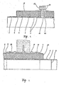
- FIGS. 3a and 3b The assembly of the elements of the pipeline system forming the subject of the invention is described in connection with FIGS. 3a and 3b. Assembly begins with the production of the continuity of the inner useful pipe 1 with the weld seam 6.
- the described multiple protective pipe system turns the continuity of the vapor-removing layer 2 provided with air passages by attaching the vapor-removing layer consisting of the fibrous heat-insulating material Layer 7 made.
- a waterproof layer 14 is formed on this by hand application, which expediently consists of the same material as the inner waterproof protective layer 4 or a plastic that is compatible with it. When producing the layer, care must be taken that it is connected and that the gaps in the initial section of the casing tube 5 are completely filled.
- the thermal insulation layer 3 is supplemented in place; in our example, prefabricated shells 8 made of hard polyurethane are attached.
- This work phase is followed by the production of part 16 of the waterproof protective layer 4; in this way the waterway was blocked off many times.
- the continuity of the casing tube 5 with the sleeve 18 with the rubber ring 12 is secured. posed.
- the inner elastic, watertight safety protective layer 4 is not designed continuously over the entire length of the tube section.
- the foam layer in the pipeline can be divided into sections and blocked off per section, whereby the effect of damage is only exerted on the given section.
- this solution can also be used with the pipes continuously provided with the waterproof protective layer 4.
- the assembly technology described above can also be used for the repair of pipes with a traditional structure which are produced in the customary manner and insulated in the jacket pipe.
- the main advantage shows that the effect of Repair, spreads over the actually treated section.
- the fixed point element providing the anchoring can be implemented, for example, in the embodiment shown in FIG.
- the fixed point element is attached to the one on the useful tube 1.
- Washer 20 provided, which are made of a suitable strength, e.g. Sheet steel is made and is used to dissipate the forces occurring on the useful pipe 1 from various origins and to maintain the line point in its fixed position.
- the disk 20 is provided in the vicinity of the useful pipe 1 with the air-guiding openings 21, expediently with bores, which ensure the continuity of the air passages of the vapor-removing layer along the working pipe 1.
- the jacket of the fixed point element is formed by two flanged tubes 19, which are arranged on both sides of the disk of the fixed point element with the interposition of a sealing plate 22 known per se and are connected with the screws 23.
- the waterproof protective layer 4 can also be configured in the fixed point element.
- the line or at certain points. certain sections, expediently the vapor-dissipating layer 2 is connected to a large air space in the insulation terminations in the shafts / FIG. 5 /, and in such a way that on the useful pipe 1 the vapor-dissipating layer 2 / which is expediently produced from a fibrous inorganic thermal insulation material /, continuously , on the inside of the building: protruding pipe section, beyond the insulation limit becomes.
- the waterproof protective layer 4 a water-impermeable film is produced. In this way, the penetration of the water is practically ruled out, while at the same time the possibility of ventilation of the insulation system and evaporation of the water from the insulation material is maintained.
- the embodied according to the invention can insulated pipe of a building to be performed shown in Figure 5 o wall sleeve 24 through the wall with the aid of; the sleeve has a disk-shaped projection for fastening in the wall and for performing the water insulation in a manner known per se.
- the wall sleeve 24 is expediently provided with two inner grooves each, which enable the design of the double-security seal in the outer pair of grooves by the arrangement of the sealing rings 12, while with the aid of the filling holes 13 present in the inner pair of grooves one with the material of the waterproof protective layer 4 matching material is filled.
- a known spring-body compensator 26 is used in the assembly of the heat-insulated pipe elements with improved properties, the pipe element 33 of which is attached to the useful pipe 1 / in the case of a steel pipe with the weld 6 /.
- the extension of the vapor-removing layer 2 to the limit of the compensator waves is carried out by the arrangement of the fibrous heat insulating material 27.
- the continuity of the heat insulation in the area of the spring body compensator 26 is achieved by using a half-shell-shaped heat insulation layer 26 moderately made of hard polyurethane foam on the conduit, and also a half-shell-shaped heat insulation layer 29, which places the clothing tube of the spring body compensator 26.
- the heat insulation layers 28, 29 are fixed in their position, the gap between them is closed with the cement 30, which expediently consists of a less waterproof protective layer 4 of identical material, but has the desired consistency.
- the sleeve 31 is pulled over the spring compensator 26; the sleeve is designed in its central section with an enlarged diameter, so it can be suitably provided on the inside with the thermal insulation 32 made of hard polyurethane foam, whereby the full thermal insulation of the piping system is also achieved in this section.
- the two ends of the sleeve 31 are advantageously each provided with two internal grooves. those, the outer pair serves to receive the sealing ring 12, while the filling bores 13 of the inner pair enable the filling of a filling material / identical to the material of the waterproof protective layer 4 /.
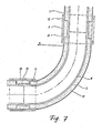
- FIG. 7 illustrates an exemplary embodiment of the heat-insulated curved tube according to the invention, and a further possibility for connecting the elements.
- the curved pipe 15 is present, which in our embodiment is provided with a sleeve 34 - for performing the adhesive connection.
- the jacket pipe 17 and the pipe 15 have a common center.
- both elbow pipes are filled with mineral material and made from a glass fiber reinforced plastic that hardens under the effect of heat; the waterproof protective layer 4 is bare applied to the ends of the jacket pipe.
- the space between the useful pipe and the jacket pipe is expediently filled with the heat insulating layer 3 made of rigid polyurethane foam.
- the conical end of the useful pipe is inserted into the sleeve 34 of the curved pipe 15 and - in our embodiment - glued to it.
- the heat-insulating half-shells 8 are put on and the sleeve 35 / which is expediently made of a glass fiber reinforced plastic / is pulled over the joint.
- the rubber rings 12 are inserted in the grooves of the sleeve in advance.
- the space between the sleeve 35 and the half-shells 8 is filled via the filling bore 36 with a material corresponding to the material of the waterproof protective layer 4; After the plastic has hardened, the continuity of the waterproof safety protective layer is guaranteed.
Abstract
Description
Die Erfindung bezieht sich auf Rohrleitungselemente und Verbindungselemente von wärmeisolierten Rohrleitungs - systemen,desweiteren auf das Verfahren zur Herstellung der Rohrleitungselemente und Verbindungselemente und deren Zusammenbau in ein Rohrleitungssystem.The invention relates to piping elements and connecting elements of heat-insulated piping systems, furthermore to the method for producing the piping elements and connecting elements and their assembly in a piping system.
Im Kreise der zur Förderung von flüssigen und/oder gasförmigen Materialien dienenden bekannten Rohrleitungen spielen die Heiz-und Nutzwasserleitungen der Fernheiz- ung,sowie die sonstigen,zur Förderung von Warmwasser, industriellem Dampf und Kaltwasser dienenden Leitungen, sowie die Leitungen der Kühl-und Ölindustrie eine bedeutende Rolle; bei deisen Leitungen muss für die Wärmeisolierung gesorgt werden. Zur Isolierung der er - wähnten Rohrleitungen,sowie zum Schutz des'Leitungsrohrs und der Wärmeisolierung selbst sind zahlreiche Lösungen bekannt.The heating and utility water pipes of district heating, as well as the other pipes for the conveyance of hot water, industrial steam and cold water, as well as the pipes of the cooling and oil industry play in the circle of the known pipelines used to convey liquid and / or gaseous materials an important role; Thermal insulation must be provided for these lines. To isolate the he - mentioned pipelines, as well as to protect the 'line pipe and the thermal insulation itself many solutions are known.
Es sind Verfahren bekannt,im Laufe dessen das aus Stahl verfertigte Nutzrohr/ Innenrohr/ mit einem Mantelrohr aus Kunststoff umhüllt wird,während als Wärmeisolierung der den zwischen den beiden Rohren vorhandenen Raum ausfüllende Polyurethanschaum dient.Methods are known in the course of which the useful tube / inner tube / made of steel is encased with a plastic jacket tube, while the polyurethane foam which fills the space between the two tubes serves as thermal insulation.
Im allgemeinen wird die Verbindung zwischen den Mantelrohren und den Profilen unter Zuhilfenahme einer Dichtung mit Gummiringen oder einer Manschette aus einem thermisch schrumpfenden Kunststoff hergestellt. Bei . jeder der erwähnten Dichtungslösungen besteht die Forderung der vollkommenen WasserundurchläEsigkeit, da die geringste eindringende Wassermenge den Polyurethanschaumstoff der wärmeisolierenden Schicht chemisch beeinträchtigt bzw. die sich aus dem Wasser bildenden Dämpfe eine mechanische Zerstörung bei dem Schaum hervorrufen. Dem Schadhaftwerden der Schaumschicht folgend,infolge der Verschlechterung der Wärmeisolierung wird die Temperatur des Kunstsoffmantelsrohrs dermassen steigen, dass das Mantelrohr vollkommen zugrundegeht. Desweiteren ruft die eindringende Wassermenge die Korrosion des Stahlrohrs hervor,was bei einer hohen Betriebstemperatur, zum kurzfristigen Zugrundegehen des Stahlrohrs führt.Die Rohre können keineswegs auf einer befriedigenden Weise ausgebessert werden,wobei eine einzige Fehlerstelle das Zugrundegehen einer langen Strecke mit sich bringt. Über das strukturelle Schadhaftwerden erhöht sich der Wärmeverlust des Leitungssystems in einem bedeutenden Mass, wodurch wesentliche Energieverluste auftreten.In general, the connection between the casing pipes and the profiles is made with the aid of a seal with rubber rings or a sleeve made of a thermally shrinking plastic. At. each of said seal solutions is the requirement of perfect Wasserundurchlä E sigkeit because the slightest amount of water penetrating the poly Chemically impaired urethane foam of the heat-insulating layer or the vapors formed from the water cause mechanical destruction of the foam. As a result of the foam layer becoming damaged, as a result of the deterioration in the thermal insulation, the temperature of the plastic jacket tube will rise to such an extent that the jacket tube is completely destroyed. Furthermore, the penetration of water causes the corrosion of the steel pipe, which, at a high operating temperature, leads to the short-term deterioration of the steel pipe. The pipes can in no way be repaired in a satisfactory manner, with a single defect causing the damage of a long distance. Structural damage increases the heat loss of the pipe system to a significant extent, which causes significant energy losses.
Die gegenwärtig bekannten Lösungen können die erwähnten negativen Erscheinungnen nur beschränkt verhindern,so wird die Anwendung derartiger Systeme bei unter dem Bodenwasser liegenden Leitungen praktisch nicht einmal vorgeschlagen.The currently known solutions can only prevent the mentioned negative phenomena to a limited extent, so the use of such systems for pipes lying under the groundwater is practically not even suggested.
Der grösste Nachteil der bekannten Lösungen besteht darin, dass sie in der Hinsicht der Isolierung gegenüber dem eindringenden Wasser keine Sicherheit bieten,auf dieser Weise ruft eine aus der fehlerhaften Herstellung der Dichtungen oder aus infolge des nicht bestimmungsgemässen Betriebes entstehendem Fehler resultierende Un - dichtheit das eindeutige Schadhaftwerden der Leitung hervor.Die Sicherstellung einer praktisch vollwertigen Wasserundurchlässigkeit mit hohen Forderungen kann durch einen einstufigen Schutz keineswegs befriedigenderweise erreicht werden.The main disadvantage of the known solutions is that they do not offer any security with regard to the insulation against the ingress of water. In this way, an untightness resulting from the faulty manufacture of the seals or from a defect resulting from improper operation calls for the clear The assurance of a practically full water impermeability with high demands can by no means be achieved satisfactorily by a one-stage protection.
Eine weitere schadhafte Wirkung kann die während des Zusammenbaues bzw.der Montage in dem geschlossenen System eingeschlossene Wassermenge verursachen. Im allgemeinen ist bei den bekannten Lösungen die Abfuhr,der derweise eingeschlossenen Wassermenge nicht gelöst.Another damaging effect can be caused by the amount of water trapped in the closed system during assembly or assembly. In general, the removal of the amount of water thus enclosed is not solved in the known solutions.
Sowohl die Verhinderung der ausseren Wassereindringung, wie auch die Ermöglichung der Entfernung der eingeschlossenen Wassermenge würde zur Erhöhung der Betriebssicherheit und Verlängerung der Lebensdauer der Systeme beitragen.The prevention of external water penetration as well as the removal of the enclosed amount of water would help to increase operational safety and extend the life of the systems.
Gewisse synthetische Rohre,wie z.B. PVC-Rohre sind zur Ertragung der dauerhaften Einwirkung der Sonnenbestrahlung nicht geeignet,so können die auf der Bodenfläche oder an Säulen,im Freien angeordneten Leitungen mit solchen Bemantelungen nicht ausgeführt werden. Die im allgemeinen verwendeten thermoplastischen Rohre können einer höheren Wärmebelastung nicht unterworfen werden. Die erwähnten Umstände beschränken den Kreis der Verwendung und in vielen Fällen wird die Ausnützung der vollen Kapazität der,kostaufwendigen Fertigungsanlagen nicht ermöglicht. Ferner besteht die Tatsache, dass die Kunststoffe verhältnismässig leicht schadhaft werden,so kann der Schutz der mit einem synthetischen Mantel isolierten Rohre gegenüber solchen Einwirkungen,mit deren Vorkommen während des Gebrauches in der Praxis re 1 gerechnet werden muss,keineswegs als vollkommen befriedigend betrachtet werden.Certain synthetic pipes, such as PVC pipes are not suitable for enduring the long-term exposure to solar radiation, so the cables arranged on the floor or on pillars or in the open cannot be made with such coatings. The thermoplastic pipes generally used cannot be subjected to a higher thermal load. The circumstances mentioned limit the range of use and in many cases the full capacity of the costly manufacturing facilities cannot be used. Furthermore, there is the fact that the plastics are relatively easily damaged, so the protection of the pipes insulated with a synthetic jacket against such effects, the occurrence of which must be expected during use in practice re 1, can by no means be regarded as completely satisfactory.
Der Erfindung wurde das Ziel gesetzt ein wärmeisoliertes Rohrleitungssystem zu entwickeln,dessen Rohrleitungs-und Verbindungselemente die Beseitigung der erwähnten Mangelhaftigkeiten bei den, aus den erwähnten Elementen erbauten Rohrleitungssystemen sicherstellen.The aim of the invention was to develop a heat-insulated piping system, the piping and connecting elements of which ensure the elimination of the deficiencies mentioned in the piping systems built from the elements mentioned.
Es wurde uns die Aufgabe gestellt durch die Anwendung der erfindungsgemässen Lösung und des zum Zusammenbau dienenden Verfahrens die obenbeschriebenen Fehler und Nachteile zu beseitigen und die bisher ausgestalteten Lösungen derweise zu vervollkommen,dass unter Anwendung des erfindungsgemässen Verfahrens vorisolierte Rohrelemente und Leitungen gleicherweise hergestellt werden können,die als Luftleitungen, unterirdische Leitungen oder als dem Bodenwasserdruck ausgesetzte,isolierte Unterwasserleitungen verwendet werden . Die in dem Verfahren verborgene Flexibilität soll eine wirtschaftliche Verwendung innerhalb des weitesten Aufwendungskreises ermöglichen. Die Ermöglichung der allgemeinen Verwendbarkeit des Isolierstoffes mit ausge- zeichneten Isolierfähigkeiten soll auch dort zur Ersparung an Wärmeenergie in dem Betrieb der Leitungen führen, wo die Anwendung solcher vorisolierten Rohrleitungen bisher unmöglich war, so z.B. bei Luftleitungen und unter dem Bodenwasser verlegten Leitungen. Durch die in dem Werk vorgenommene Vorisolierung soll die an Ort und Stdle durchzuführende Arbeit bedeutend vermindert und die Dauer des Zusammenbaues urdMontage wesentlich verkürzt werden können.We were given the task of using the solution according to the invention and the assembly method to eliminate the errors and disadvantages described above and to perfect the solutions designed so far that using the method according to the invention, pre-insulated pipe elements and lines can be produced in the same way, which can be used as air lines, underground lines or as insulated underwater lines exposed to soil water pressure. The flexibility hidden in the process is intended to enable economical use within the broadest scope of expenditure. Enabling the general applicability of the insulating material with out - recorded insulating capabilities should also lead there to a saving of heat energy in the operation of the lines where the use of such pre-insulated pipes were previously impossible, such as in air ducts and under the ground water routed cables. The pre-insulation carried out in the factory is said to significantly reduce the work to be carried out on site and hours and to significantly shorten the assembly time and assembly.
Die Erfindung beruht auf der Erkenntnis,indem mit einem geeigneten Verfortigungsverfahren und durch die geeignete. Wahl und Zusammensetzung der Materialien, unter Anwend-und der gleichen Produktionsanlagen ein sich den jeweiligen Ansprüchen anpassendes Isolierungs-und Schutzsystem an dem Leitungsrohr /Nutzrohr/ erzeugt werden kann,das im Vergleich zu dem bisher im allgemeinen verwendeten einfachen Schutzsystem ein sekundär und ein tertiäres Schutzsystem darstellt.The invention is based on the finding by using a suitable comforting method and by the appropriate one. Choice and composition of the materials, under application and the same production systems, an insulation and protection system adapting to the respective requirements can be produced on the conduit / useful pipe / which, in comparison to the simple protection system previously used in general, has a secondary and a tertiary protection system represents.
Werden nun das Isolierungs-und Schutzsystem und der Schutz des Leitungsrohrs auf der geschilderten Weise ausgestaltet, bieten der von dem Mantelrohr angebotene primäre äussere Schutz und das von den Beschädigungen,der Undichtheit der Verbindungen,der Anwesenheit des im Laufe der Errichtung eingeschlossenen Wassers unabhängig einwand - frei funktionierende innere Schutzsystem /oder mehrere Schutzsysteme/ eine gebührende Sicherheit gegenüber dem Schadhaftwerden an. Aus den zweckmässig gewählten Komponenten,durch die geeignete Wahl der Kunststoffe wird durch die Anwendung des erfindungsgemässen Verfahrens an dem äusseren,das Mantelrohr begrenzenden Teil und den damit verbundenen Stellen eine zusammenhängende Schutzschicht mit geschlossener Struktur zuetandege- bracht,die elastisch ist und von dem Matelrohr gegenüber mechanischen Beschädigungen geschützt wird,daher auch in Extremfällen die Wasserundurchlässigkeit gewährleistet.If the insulation and protection system and the protection of the conduit are designed in the manner described, the primary external protection offered by the casing pipe and that which is independent of the damage, the leakage of the connections and the presence of the water enclosed in the course of the erection, provide perfect protection. free-functioning internal protection system / or several protection systems / due security against damage. From the expediently selected components, through the suitable choice of the plastics, the application of the method according to the invention to the outer part delimiting the jacket tube and the associated points brings about a coherent protective layer with a closed structure, which is elastic and opposite the mat tube mechanical damage is protected, therefore ensuring water tightness even in extreme cases.
Im Laufe des erfindungsgemäseen Verfahrens wird an dem Innenteil der Isolierung eine mit Luftgängen ausgestaltete Schicht erzeugt,die die Funktion der Dampfabfuhr zu erfüllen fähig ist,wodurch der Austritt des in dem Isolierstoff steckengebliebenen Wasserdampfes oder sonstiges gasförmiges Spaltproduktes in einen zweckdienlichen grossen Luftraum /z.B. in einen Armaturschacht/ ermöglicht und als Erfolg die eventuell schadhafte Wirkung beseitigt wird.In the course of the method according to the invention, a layer designed with air passages is produced on the inner part of the insulation, which layer is capable of fulfilling the function of steam removal, as a result of which the water vapor or other gaseous fission product stuck in the insulating material escapes into a suitable large air space / e.g. into a fitting shaft / enabled and, as a success, the possibly defective effect is eliminated.
Dieser zweckmässige Plusschutz schützt entlang der gesamte In Leitung überall und gleichmässig das Leitungsrohr bzw, die wärmeisolierende Schicht,da durch die Anwendung des erfindungsgemässen Verfahrens auch an den Verbindungsstellen der Rohrelemente und der Rohrprofile für die Kontinuität der äusseren Schutzschichten und der. inneren Dampfabfuhr gesorgt worden ist. Überdies erfüllt die dampfabführende Schicht,die zweckmässig aus einem unorganischen Faserstoff hergestellt wird,eine wärmeisolierende Funktion und schützt die gegenüber den unmittelbaren hohen Wärmeeinwikrungen empfindlichere Wärmeisolierschicht aus Polyurethanschaum.This expedient plus protection protects the conduit or the heat-insulating layer along the entire in-line everywhere and evenly, since the method according to the invention also applies at the junctures of the pipe elements and the pipe profiles for the continuity of the outer protective layers and the. internal steam removal has been provided. In addition, the vapor-dissipating layer, which is expediently produced from an inorganic fiber material, fulfills a heat-insulating function and protects the heat-insulating layer made of polyurethane foam, which is more sensitive to the immediate high levels of heat.
Die erfindungsgemässe Anordnung und das Verfahren können dort vorteilhaft verwendet werden,wo das Nutzrohr ein übliches Stahlrohr oder ein aus sonstigem Grundstoff ver- fertigtes,gegenüber der chemischen Wirkung,Temperatur und Druck des geförderten Mediums beständiges Leitungsrohr,so z.B. ein glasfaserverstärktes Kunststoffrohr oder Kunstharz- Betonrähr ist.The arrangement according to the invention and the method can be used advantageously where the useful pipe is a conventional steel pipe or a pipe made of other basic material and resistant to the chemical action, temperature and pressure of the medium being conveyed, e.g. is a glass fiber reinforced plastic tube or synthetic resin concrete tube.
Desweitern haben wir es erkannt,dass bei der Herstellung und Funktion eines sekundären oder tertiären Schutz - systems das Mantelrohr,als primärer Schutz, immer in der Abhängigkeit des jeweiligen Bedarfniveaus ausgestaltet werden kann. Unter Betrachtnahme der Ansprüche und der Wirtschaftlichkeit steht auf dieser Weise eine äusserst flexibile, dem jeweiligen Bedarf weitgehend anpassbare Bemantelung mit wirtschaftlicher Lösung zur Verfügung.We have also recognized that in the manufacture and function of a secondary or tertiary protection system, the casing tube, as primary protection, can always be designed depending on the respective level of need. Taking into account the requirements and the cost-effectiveness, this provides an extremely flexible coating with an economical solution that can be largely adapted to the respective requirements.
Unter Anwendung der erfindungsgemässen Lösung können alle Nachteile beseitigt werden,die dadurch entstanden, dass das Material des Mantelrohrs das Anwendungsgebiet stark eingeschränkt hatte. Durch unsere Erfindung ist das vorisolierte Rohrleitungsystem zum allgemeinen Gebrauch geeignet,wenn das vorherbeschriebene innere Schutzsystem mit einem die Umgebungs-und Temperatureinwirkungen gut tolerierenden und bis zu dem er-, forderlichen Mass festen Mantelrohr gepaart wird.Using the solution according to the invention, all the disadvantages that resulted from the fact that the material of the casing tube had severely restricted the field of application can be eliminated. Through our invention, the pre-insulated piping system is suitable for general use if the previously described inner protection system is paired with a casing pipe which is well tolerant of the environmental and temperature effects and is solid to the required extent.
Als Mantelrohr in einer in dem Boden eingebetteten und, , höheren Wärmeeinwirkungen ausgesetzten Leitung wird z.B. vorteilhaft ein auf Wirkung der Wärme erhärtendes Kunststoffrohr oder ein kunststoffgebundenes Mantelrohr mit Mineralstoffüllung eingesetzt. Bei mittleren thermischen . Belastungen haben sich die thermoplastischen synthetischen Mantelrohre gut bewährt. Im Freien angeordnete polierte Rohrleitungen können recht vorteilhaft ausgestaltet werden, wenn als Mantelrohr ein,die atmosphärischen Verhältnisse gut tolerierendes Metallrohr mit geringer Wandstärke verwendet wird,das entweder bereits im Material korrosionbeständig ist oder mit einem separaten Korrosionschutz versehen ist. Bei der erfindungsgemässen Lösung wird als Metallblechrohr ein spiral verfalztes oder , geschweisstes Aluminiumrohr oder ähnliches verwendet.As a casing pipe in a pipe embedded in the ground and exposed to higher heat effects e.g. advantageously used a thermosetting plastic tube or a plastic-bound jacket tube with mineral filling. With medium thermal. The thermoplastic synthetic jacket pipes have proven their worth. Polished pipelines arranged outdoors can be designed to be quite advantageous if a metal pipe with a small wall thickness, which tolerates the atmospheric conditions and which is either corrosion-resistant in the material or is provided with a separate corrosion protection, is used as the casing pipe. In the solution according to the invention, a spirally folded or welded aluminum tube or the like is used as the sheet metal tube.
Werden nun das Nutzrohr und Mantelrohr in gegenseitigem 'Einklang gewählt,können wir uns unter Anwendung der erfindungsgemässen Schutzsystems und der isolierten Leitung weitgehend,nach den tatsächlichen Anwenndungsumständen richten.If the useful pipe and the casing pipe are now selected in mutual harmony, we can largely use the protection system according to the invention and the insulated line to comply with the actual circumstances of the application.
Der Erfindung knüpfen sich zahlreiche vorteilhafte und neuartige Mehrwirkungen an,die bei den.gegenwärtig bekannten,zu ähnlichen Zwecken dienenden Lösungne nicht aufzufinden sind. Im Sinne der Erfindung kann ein isoliertes. Rohrleitungsystem zustandegebracht werden,das gegenüber den atmosphärischen und Kraftwirkungen in dem gewünschten Mass beständig ist,das Eindringen des Wassers.mit mehrfacher Sicherheit verhindert, dessen Wärmeisolierung die Wärmeverluste auf das technische Minimum herabsetzt und dessen der Rohrlängeeinheit zugeordneter Bedarf an lebendiger Arbeit an der Baustelle äusserst gering ist, dabei kann der Zusammenbau der Leitung aus den vorisolierten Elementen zeitgemäss,gut organisierbar und gut mechanisierbar vorgenommen werden, die mit dem Aufrüsten,der Verschalung und Absenkung des Bodenwasserniveaus zusammenhängenden Tätigkeiten können teilweise weggelassen bzw. reduziert werden,wobei die gesamte Realisierung eine kürzere Zeitspanne in Anspruch nimmt.The invention is associated with numerous advantageous and novel multi-effects which cannot be found in the currently known solutions which serve similar purposes. For the purposes of the invention, an isolated. Pipeline system that is resistant to the atmospheric and force effects to the desired extent, prevents the ingress of water with multiple security, whose thermal insulation reduces heat losses to the technical minimum and whose need for living work on the construction site associated with the pipe length unit is extremely low assembly the line from the pre-insulated elements can be made up-to-date, well organized and mechanized, the activities related to the upgrading, formwork and lowering of the soil water level can be partially omitted or reduced, the entire implementation taking a shorter time span.
All dies vorausgeschickt,kann es festgestellt werden, dass die Erfindung sich auf ein wärmeisoliertes Rohrleitungsystem ,sowie auf dessen betriebliche Vorfertigung und Zusammenbau-Montage in-situ bezieht,welches Rohrleitungsystem zur Förderung von flüssigen und/oder gasförmigen Medien,insbesondere wänmetragenden Medien in einer isolierten Leitung dient, das aus dem an sich bekannten inneren Nutzrohr ,dem damit konzentrischen ausseren Mantelrohr und dem den zwischen den beiden Rohren vorhandenen Raum ausfüllenden Wärmeisolierstoff besteht und im Sinne der Erfindung an der Grenzfläche der Wärmeisolierung und dem Mantelrohr eine wasserdichte innere Schutzschicht ausge- . staltet ist,während an dem das innere Nutzrohr angrenzenden Teil eine eventuelle Belüftungsschicht geformt wird, die nach erfolgtem Zusammenbau zweckdienlich mit,dem Bedienungs-oder Armaturschacht von groasem Luftraum in Verbindung steht. Die, derweise ausgestaltetsn,in dem Werk vorgefertigten geraden oder gebogenen Rohre, die Abzweigungen der Rohrabschhitte,sowie die Verankerung sicherstellende Rohrprofile werden mittels einer das Eindringen des Wasser ausschliessenden,aber die Ventilation entlang des Innenrohrs ermöglichenden Kupplung, sowie mit den übrigens bekannten Sperr-und Bedienungsarmaturen an der Baustelle in ein Leitungssystem zu - sammengebaut.In dem verbesserten,im voraus wärmeisolierten Rohrleitungsystem verhindert die wasserdichte Schutzschicht innerhalb des Mantelrohrs die Eindringung des aus der Undichtheit des Mantelrohrsystems ergebenden Wassers,wodurch die Verminderung der Isolierfähigkeit der wärmeisolierenden Schicht und im allgemeinen die Korrosiongefahr bei dem üblicherweise aus Stahl verfertigten Nutzrohr beseitigt werden.With all of this in mind, it can be stated that the invention relates to a heat-insulated piping system, as well as to its operational prefabrication and assembly assembly in situ, which piping system is used to convey liquid and / or gaseous media, in particular heat-carrying media in an insulated Pipe is used, which consists of the inner tube known per se, the concentric outer jacket tube and the thermal insulating material filling the space between the two tubes, and in the sense of the invention a waterproof inner protective layer at the interface of the thermal insulation and the jacket tube. is designed, while a possible ventilation layer is formed on the part adjoining the inner useful pipe, which, after assembly, is expediently connected to the service or fitting shaft of large air space. The straight or curved pipes prefabricated in the factory, the branches of the pipe sections, and the anchoring pipe sections are secured by means of a coupling that prevents water from penetrating but enables ventilation along the inner pipe, as well as with the known blocking and Control valves at the construction site assembled in a pipe system, in the improved, previously heat-insulated Pipe system prevents the waterproof protective layer inside the casing pipe from penetrating the water resulting from the leakage of the casing pipe system, thereby eliminating the reduction in the insulating capacity of the heat-insulating layer and generally eliminating the risk of corrosion in the commercial pipe which is usually made of steel.
Die Bezeichnung"Mantelrohr" bezieht sich auf die mit der äusseren Umgebung in direkter Berührung stehende äussere Schale,die eventuell aus mehreren Stücken besteht,oder deren Material sich,entläng der Länge des Rohleitungsystems ändern kann. Die das Nutzrohr angrenzende, mit den Luftgängen ausgetaltete Schicht sichert den Austritt der während der Montage eingeschlossenen Feuchtigkeit, wodurch deren chemische und mechanische schädliche Wirkung in der Wärmeisolierschicht beseitigt wird.The term "jacket pipe" refers to the outer shell that is in direct contact with the external environment, which may consist of several pieces, or the material of which may change along the length of the pipeline system. The layer adjacent to the useful pipe and provided with the air passages ensures the escape of the moisture enclosed during assembly, as a result of which its chemical and mechanical harmful effects in the heat insulation layer are eliminated.
Die werkmässige Herstellung der Elemente des'Rohleitung- systems ,der Zusammenbau der Elemente an der Baustelle, die Ausführung des Mantelrohrs,die Verbindung des Mantelrohrs an der Baustelle,die funktionale Kontinuität des Schutzes des Innenrohrs sicherstellende Verbindungsweise,die Durchführung der Produktion und die Ausbildung der Verankerungsprofile und Bögen bilden ebenfalls den Gegenstand der Erfindung.The factory production of the elements of the pipe system, the assembly of the elements on the construction site, the execution of the casing pipe, the connection of the casing pipe at the construction site, the functional continuity of the protection of the inner pipe ensuring the connection method, the implementation of the production and the training of the Anchoring profiles and arches also form the subject of the invention.
Die Erfindung wird anhand einiger vorteilhaften Ausführungsbeispiele,mit Hilfe der beiliegenden Zeichnung näher erläutert. Es zeigen:
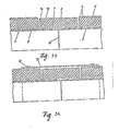
Figur 1 den schematischen Querschnitt des erfindungsgemässen Rohrleitungselements,- Figuren 2a,2b,2c die einzelnen Phasen der gegenseitigen Verbindung zweier Rohrleitungselemente,in Längsschnitt dargestellt,
- Figuren 3a,3b eine weitere Möglichkeit zur Verbindung zweier Rohr leitungselemente,
Figur 4 ein Fixpunktelement zur Verankerung des Rohrsystems,Figur 5 die Überführung eines Rohrleitungelements hindurch die Wand eines Bauobjekts,Figur 6 die Verbindungsweise zwischen dem Kompensator mit dem Federkörper und dem Rohrleitungs-° element,Figur 7 ein Ausführungsbeispiel für das Bogenrohrprofil.
- FIG. 1 shows the schematic cross section of the pipe element according to the invention,
- FIGS. 2a, 2b, 2c the individual phases of the mutual connection of two pipeline elements, shown in longitudinal section,
- Figures 3a, 3b another way of connecting two pipe line elements,
- FIG. 4 shows a fixed point element for anchoring the pipe system,
- FIG. 5 shows the transfer of a pipe element through the wall of a building,
- FIG. 6 shows the connection between the compensator with the spring body and the pipe element;
- Figure 7 shows an embodiment for the curved tube profile.
In Figur 1 ist der Querschnitt eines erfindugsgemässen Rohrleitugselements als Beispiel vorgezeigt. Das innere /z.B. aus Stahl verfertigte/ Nutzrohr 1 ist von der dampfabführendn Schicht 2, einer aus unorganischem Faserstoff /z.B.Glasfaserstoff/ bestehenden und mit offenen Luftgängen versehenen Schicht umhüllt. Die erwähnte Schicht berührend ist die Wärmeisolierschicht 3 angeordnet, die zweckmässig von einem harten Polyurethanschaum mit offenen Poren,Phenolharzschaum ,Furanharzschaum oder Wasserglasschaum gebildet ist. Gegebenenfalls können der Phenolharzschaum,der Furanharzschaum und der Wasserglasschaum hydrophobisiert werden. Der Vorteil dieser Stoffe zeigt sich in der hochgradigen Wärmetoleranz - fähigkeit.Die Wärmeisolierschicht 3 ist von einer/oder mehreren/ wasserdichten Sicherheitsschutzschicht/en/ 4 zusammenhängend umhüllt,die aus einem wasserdichten Kunststoff,zweckmässig weichem Polyurethan, Polyester, Polyäthylen,Zellulosazetat oder einem Material auf Epoxydharzbasis besteht.Die an der Sicherheitsschutzschicht gestellte Grundforderung besteht darin, dass sie eine entsprechend hohe Zerreissdehnung aufweise und gut an die begrenzenden Materialien anhafte. Die äusserste Schicht der Konstruktion wird von dem, eine entsprechende Steifheit aufweisenden,gegenüber den äusseren Medienwirkungen beständigqn,zusammenhängenden wasserdichten Mantelrohr 5 gebildet.1 shows the cross section of a pipe element according to the invention as an example. The inner /
Der Herstellungsprozess der erfindungsgemässen .vorisolierten Rohrleitungsqlemente /gerade Rohre,Rohrbögen,Abzweig- rohre/ kann z.B. der folgende sein:
- a/ die geraden Elemente werden einfach ineinander/aufeinander gelegt;
- b/
die wasserdichte Sicherheitsschutzschicht 4 wird in Form einer Kunststoffolie aufgetragen,die an die Innenfläche desMantelrohrs 5 geklebt wird; - c/
die wasserdichte Sicherheitsschutzschicht 4 wird mit einer unmittelbaren polymerisierenden Reaktion /Polymerisations-,Polyadditions- desweiteren Polymerisation/ an der Innenfläche desMantelrohrs 5 ausgestaltet.Dieses Verfahren kann z.B. folgenderweise vorgenommen werden:- - auf die Fläche des
Nutzrohrs 1 wird die dampfabführende Schicht,zweckmässig ein Glasgewebe durch Aufwicklung aufgetragen; - - auf die Innenfläche wird das Material der wasserdichten Sicherheitsschutzschicht 4 in einem flüssigen Zustand aufgetragen,das nach erfolgter Polymerisation sich in einem elastisohen festen zusammenhängenden und wasserdichten Zustand befindet;
- - die derweise vorbereiteten Rohre werden unter Zuhilfenahme von Abstandelementen in eine konzentrische Position gebracht undzwar derweise,dass
das Nutzrohr 1 über die beiden Enden desMantelrohrs 5 bis zu einem von der Verbindungsmöglichkeit bestimmten Mass hinausreicht und nach dem Abschlieseen der Enden des zwischen den Rohren vorhandenen Raums die die wärmeisolierenden und schaumbildenden Reagenten in entsprechender Menge und vorschriftsmässiger Proportion enthaltende Mischung einfüllenä,die Warmeisolierschicht zustandegebracht wird.
- - auf die Fläche des
- a / the straight elements are simply placed one inside the other;
- b / the waterproof safety
protective layer 4 is applied in the form of a plastic film which is glued to the inner surface of thetubular casing 5; - c / the waterproof safety
protective layer 4 is designed with an immediate polymerizing reaction / polymerization, polyaddition-further polymerization / on the inner surface of thecasing tube 5. This method can be carried out, for example, as follows:- - On the surface of the
useful pipe 1, the vapor-removing layer, advantageously a glass fabric is applied by winding; - - The material of the waterproof safety
protective layer 4 is applied to the inner surface in a liquid state, which is in an elastically solid, coherent and waterproof state after the polymerization; - - The pipes prepared in this way are brought into a concentric position with the aid of spacer elements and in such a way that the
useful pipe 1 over the two ends of thecasing pipe 5 to one of the connection possibility extends beyond a certain extent and, after the ends of the space between the tubes have been closed, fill in the mixture containing the heat-insulating and foam-forming reagents in an appropriate amount and in accordance with the regulations, the heat-insulating layer is brought about.
- - On the surface of the
In dem letzterwähnten Fall wird daher sowohl die Reaktion. der Polymexisation,wie auch der Schaumbildung an dem Mantelrohr 5,bzw. in dem Raum,zwischen den Rohren auf an sich bekannter Weise erzeugt.In the latter case, therefore, both the reaction. the polymexization, as well as the foam formation on the
Durch die obenbeschriebene Polymerisationsreaktion können mehrere Schutzschichten an, der Innenwand des Mantelrohrs 5 ausgestaltet werden. Gleicherweise können auf die Innenwand des Mantelrohrs 5, mehrere Schutzschichten aufgeklebt oder aufgelegt werden. In diesem Fall können die einzelnen wasserdichten Schutzschichten aue,gleichen oder verschiedenen Materialien verfertigt werden.The above-described polymerization reaction allows multiple protective layers to be formed on the inner wall of the
Man kann auch derweise verfahren,indem nur ah einzelnen Abschnitten der Wand des Mantelrohrs 5 die wasserdichte Sicherheitsschutzschicht 4 ausgestaltet wird,bzw. auf einzelne Abschnitte der Wand des Mantelrohrs 5 weniger, auf andere Abschnitte mehr.aus der wasserdichten Schutzschicht 4 aufgetragen wird.One can also proceed in such a way that the waterproof safety
Ein Beispiel für den Verlauf des Zusammenbaus der vorisolierten Rohrleitungelemente an der Baustelle wird im Zusammenhang mit den Figuren 2a,2b und 2c beschrieben.
- - Die beiden sich anschliessenden Rohrleitungselemente werden in eine koaxiale Position gebracht,wonach die Enden der Nutzrohre 1 in einer die entsprechende Festigkeit und Dichtheit sicherstellenden Weise miteinander verbunden werden / so z.B. lassen wir die Enden der Stahl-rohre stumpf anstossen und schweissen sie
mit der Stumpfschweissnaht 6 aneinander/. - - Um die Kontinuität der dampfableitenden Schicht 2 sicherstellen zu können,wird die frei gebliebene Fläche des
Nutzrohrs 1 mit einer aufgewickelten dampfableitenden Schicht 7 aus demselben Material versehen. - -
Die Wärmeisolierschicht 3 wird durch das Aufbringen der Wärmaisolierung - die als eine Halbschale in der gleichen Stärke und von demselben Material verfertigt worden ist ― auch in den Rohrverbindungsstellen zusanegebracht. - - Zwecks Sicherstellung der Kontinuität des
Mantelrohrs 5 wird über der Anstoßstelle die Muffe 9 angeordnet,die an beiden Enden zweckmässigmit je Innennuten den äusseren Innennuten 11ist der Dichtungsring 12 eingelegt,der die primäre Dichtung zwischendem Mantelrohr 5 und der Muffe 9 gewährleistet. In den Innennuten sind dieBüllbohrungen 13 vorgesehen, die , im Laufe der Montage oben und zugänglich angeordnet sind. - - Um die Kontinuität der inneren elastischen wasserdichten Sicherheitsschutzschicht 4 gewährleisten zu können,werden' die Spalten mit demselben Material über die Füllbohrung 13 der einen Innennut 10,unter Druck solange aufgefüllt, bis das Material über die Füllbohrung 13 der anderen Innennut nach Verdrängen der Luft herausfliesst.
- - The two adjoining pipe elements are brought into a coaxial position, after which the ends of the
useful pipes 1 are connected to one another in a manner which ensures the appropriate strength and tightness / for example, we let the ends of the steel pipes butt butt and weld them together with thebutt weld 6. - - In order to be able to ensure the continuity of the vapor-dissipating
layer 2, the surface of theuseful tube 1 that is left free is provided with a wound vapor-dissipatinglayer 7 made of the same material. - - The
thermal insulation layer 3 is brought together by the application of the thermal insulation - which has been manufactured as a half-shell in the same thickness and of the same material - in the pipe connection points. - - To ensure the continuity of the
casing tube 5, the sleeve 9 is arranged above the abutment, which is expediently provided at both ends withinternal grooves inner grooves 11, the sealingring 12 is inserted, which ensures the primary seal between thecasing tube 5 and the sleeve 9. In the inner grooves, theboring holes 13 are provided, which are arranged above and accessible during assembly. - - In order to be able to ensure the continuity of the inner, elastic, watertight safety
protective layer 4, the gaps are filled with the same material via the fillinghole 13 of the oneinner groove 10 under pressure until the material flows out through the fillinghole 13 of the other inner groove after the air has been displaced .
Der Zusammenbau der Elemente des den Gegenstand der Erfindung bildenden Rohrleitungsystems wird im Zusammenhang mit den Figuren 3a und 3 b beschrieben. Die Montage beginnt mit der Herstellung der Kontinuität des inneren Nutzrohrs 1 mit der Schweissnaht 6. Aus dem geschilderten mehrfachen Schutzrohrsystem wird erstens die Kontinuität der mit Luftgängen vershenen dampfabführenden Schicht 2 durch das Anbringen der aus dem faserigen Wärmeisolierstoff bestehenden dampfabführenden Schicht 7 hergestellt. Auf dieser wird durch Auftragen mit der Hand eine wasserdichte Schicht 14 gebildet,die zweckmässig aus dem gleichen Material,wie die innere wasserdichte Schutzschichte 4 oder einem damit verträglichen Kunststoff besteht. Bei der Herstellung der Schicht muss man darauf achten,dass diese zusammenhängend sei, und die Spalten bei der Anfangsstrecke des Mantelrohrs 5 restlos ausfülle. Darauffolgend wird die Wärmeisolierschicht 3 an Ort und Stelle ergänzt ; bei unserem Beispiel werden , vorgefertigte Schalen 8 aus hartem Polyurethan aufgesetzt. Dieser Arbeitsphase folgt die Herstellung des Teils 16 der wasserdichten Schutzschicht 4; auf dieser Weise wurde die Wasserbahn vielfach abgesperrt. Bei unserem Ausführungsbeispiel wird die Kontinuität des Mantelrohrs 5 mit der Überschiebmuffe 18 mit dem Gummiring 12 sicher- . gestellt.The assembly of the elements of the pipeline system forming the subject of the invention is described in connection with FIGS. 3a and 3b. Assembly begins with the production of the continuity of the inner
Wie wir es bereits erwähnt haben,wird die ennere elastische wasserdichte Sicherheitsschutzschicht 4 nicht in der gesamten,Länge des Rohrabschnitts kontinuierlich ausgestaltet. In diesen Fällen kann zur Erhöhung der Sicherheit die Schaumschicht in der Rohrleitung in Strecken aufgeteilt und je Strecke abgesperrt werden, wodurch die Wirkung des Schadhaftwerdens, sich nur auf den gegebenen Abschnitt ausgeübt wird. Selbstverständlich kann diese Lösung auch bei den mit der wasserdichten Schutzschicht 4 kontinuierlich versehenen Rohren verwendet werden.As we have already mentioned, the inner elastic, watertight safety
Die obengeschilderte Montagetechnologie kann auch für die Reparatur von auf üblicher Weise hergestellten,in dem Mantelrohr isolierten,Rohren mit traditioneller Struktur verwendet werden. In diesen Fällen zeigt sich der wichtigste Vorteil darin,dass die Wirkung der Reparatur ,sich hinüber den tatsächlich behandelten Abschnitt ausbreitet.The assembly technology described above can also be used for the repair of pipes with a traditional structure which are produced in the customary manner and insulated in the jacket pipe. In these cases, the main advantage shows that the effect of Repair, spreads over the actually treated section.
Das für die Verankerung sor gende Fixpunktelement kann z.B in der in Figur 4 dargestellten Ausführung realisiert werden. Das Fixpunktelement ist mit der,an dem Nutzrohr 1 befestigten. Scheibe20 versehen, die aus einem eine geeignete Festigkeit aufweisenden Grundstoff,z.B. Stahlblech verfertigt ist und zur Abführung der auf dem Nutzrohr 1 auftretenden Kräfte verschiedener Herkunft und zur Behaltung des Leitungspunkts in seiner fixen Position dient. Die Scheibe 20 wird in der Nähe des Nutzrohrs 1 mit den luftführenden Öffnungen 21,zweckmässig mit Bohrungen versehen, die die Kontinuität der Luftgänge der dampfabführenden Schicht entlang des Nutzrohrs 1 sicherstellen.The fixed point element providing the anchoring can be implemented, for example, in the embodiment shown in FIG. The fixed point element is attached to the one on the
Der Mantel des Fixpunktelements wird von zwei geflanschten Rohren 19 gebildet,die an beiden Seiten der Scheibe des Fixpunktelements unter Zwischenschaltung einer an sich bekannten Dichtungsplatte 22 ,angeordnet und'mit den Schrauben 23 verbunden werden. Die wasserdichte Schutzschicht 4 kann auch in dem Fixpunktelement ausgestaltet werden.The jacket of the fixed point element is formed by two
Bei dem Zusammenbau der erfindungsgemässen vorisolierten Elemente in ein Rohrletungssystem wird an bestimmten Punkten der Leitung bzw. an. gewissen Abschnitten,zweckmässig bei den in den Schächten vorhandenen Isolierungsbeendigungen die dampfabführende Schicht 2 mit einem grossen Luftraum verbunden /Figur 5/,undzwar derweise, dass auf dem Nutzrohr 1 die dampfabführende Schicht 2 /die zweckmässig aus einem faserigen unorganischen Wärmeisolierstoff verfertigt wird/,kontinuierlich, auf dem in den Innenraum des Bauubjektes hine:inragenden Rohrabschnitt,über die Isolierungsgrenze hinaus,ausgestaltet wird. Als Fortsetzung der wasserdichten Schutzschicht 4 wird ein wasserundurchlässiger Film erzeugt. Auf dieser Weise wird die Eindringung des Wassers praktisch ausgeschlossen,gleichzeitig ist die Möglichkeit zur Belüftung des Isoliersystems, zur Verdampfung des Wassers aud dem Isolierstoff aufrechterhalten.When assembling the pre-insulated elements according to the invention in a pipe system, the line or at certain points. certain sections, expediently the vapor-dissipating
Das im Sinne der Erfindung ausgestaltete isolierte Rohr kann unter Zuhilfenahme einer in Figur 5 dargestellteno Wandmuffe 24 hindurch die Wand eines Gebäudes geführt werden; die Muffe weist einen scheibenförmigen Vorsprung zur Befestigung in der Wand und zur Ausführung der Wasserisolierung auf der an sich bekannten Weise auf. Zweckdienlich wird die Wandmuffe 24 mit je zwei Innennuten versehen, die die Gestaltung der die doppelte Sicherheit bietenden Dichtung in dem äusseren Nutenpaar durch die Anordnung der Dichtungsringe 12 ermöglichen, während mit Hilfe der in dem innenliegenden Nutenpaar vorhandenen Füllbohrungen 13 ein mit dem Material der wasserdichten Schutzschicht 4 übereinstimmendes Material eingefüllt wird.The embodied according to the invention can insulated pipe of a building to be performed shown in Figure 5 o
Zur Aufnahme der Wärmeäusdehnung wird bei dem Zusammenbau der über verbesserte Eigenschaften verfügenden wärmeisolierten Rohrleitungselemente ein an sich bekannter Federkörper-Kompensator 26 verwendet,dessen Rohreleinent 33 an dem Nutzrohr 1 befestigt wird / bei einem Stahlrohr mit der Schweissnaht 6/.In order to absorb the thermal expansion, a known spring-
Die Verlängerung der dampfabführenden Schicht 2 bis zu der Grenze der Kompensator-Wellen wird durch die Anordnung des faserigen Wärmeisolierstoffes 27 vorgenommen. Die Kontinuität der Wärmeisolierung im Bereich des Federkörper-Kompensators 26 wird dadurch erreicht, indem man eine halbschalenfürmige Wärmeisolierschicht 26, zweckmässig aus hartem Polyurethanschaum auf das Leitungrohr, sowie eine ebenfalls halbschalenförmige Wärmeisolierschicht 29 auf,das Bekleidungsrohr des Federkörper-Kompensators 26 auflegt. Die Wärmeisolierungsschichten 28,29 werden in ihrer Position befestigt,die dazwischen vorhandene Spalte wird mit dem Kitt 30 verschlossen,der zweckmässig aus einem minder wasserdichten Schutzschicht 4 identischen Material besteht,aber über die gewünschte Konsistenz verfügt. Darauffolgend wird die Muffe 31 über den Federkörper-Kompensator 26 gezogen; die Muffe ist in ihrem mitteleren Abschnitt mit einem vergrösserten Durchmesser ausgestaltet,so kann sie innen zweckmässig mit der Wärmeisolierung 32 aus hartem Polyurethanschaum versehen werden, wodurch auch in diesem Abschnitt die vollwertige Wärmeisolation des Leitungssystems erreicht wird. Vorteilhaft sind die beiden Enden der Muffe 31 mit je zwei Innennuten versehen, aus . denen,das äussere Paar zur Aufnahme des Dichtungringes 12 dient,während die Füllbohrungen 13 des inneren Paars die Einfüllung eines Füllmaterials / identisch mit dem Material der wasserdichten Schutzschicht 4/ ermöglichen.The extension of the vapor-removing
In Figur 7 ist ein Ausführungsbeispiel für das erfindungsgemässe wärmeisolierte Bogenrohr,sowie eine weitere , Möglichkeit zur Verbindung der Elemente veranschaulicht. In dem gewölbten Abschnitt des Nutzrohrs ist das Bogenrohr 15 vorhanden,das bei unserem Ausführungsbeispiel mit einer Muffe 34 - zur Durchführung der Klebeverbindung versehen ist. Das Mantelbogenrohr 17 und, das Bogenrohr 15 haben einen gemeinsamen Mittelpunkt. Bei unserem Ausführungsbeispiel sind beide Bogenrohre mit Mineralstoff gefüllt und aus einem glasfaserverstärkten unter Wärmewirkung erhärtenden Kunststoff verfertigt; die wasserdichte Schutzschicht 4 ist bloss an den Enden des Mantelbogenrohrs aufgetragen. Der Raum zwischen dem Nutzrohr und dem Mantelbogenrohr wird zweckdienlich mit der Wärmeisolierschicht 3 aus Polyurethanhartschaum ausgefüllt. Bei dem Zusammenbau der Elemente der wärmeisolierten.Leitung wird das konische Ende des Nutzrohrs in die Muffe 34 des Bogenrohrs 15 eingesteckt und - bei unserem Ausführungsbeispiel -- damit zusammengeklebt. Darauffolgend werden die wärmeisolierenden Halbschalen 8 aufgesetzt und die Muffe 35 / die zweckmässig aus einem glasfaserverstärkten Kunstoff hergestellt wird/ wird über die Stoßstelle gezogen. In die Rillen der Muffe werden die Gummiringe 12 im voraus eingesetzt. Der Raum zwischen der Muffe 35 und den Halbschalen 8 wird über die Füllbohrung 36 mit einem,dem Material der wasserdichten Schutzschicht 4 entsprechenden Material ausgefüllt; nach erfolgter Erhärtung des Kunststoffes ist die Kontinuität, der wasserdichten Sicherheitsschutzschicht gewährleistet.FIG. 7 illustrates an exemplary embodiment of the heat-insulated curved tube according to the invention, and a further possibility for connecting the elements. In the curved section of the useful pipe, the
Claims (18)
Priority Applications (1)
| Application Number | Priority Date | Filing Date | Title |
|---|---|---|---|
| AT81105317T ATE18093T1 (en) | 1980-07-17 | 1981-07-08 | HEAT-INSULATED PIPE ELEMENT AND PIPE SYSTEM FROM SUCH PIPE ELEMENTS, AND METHOD FOR MANUFACTURING THE PIPE ELEMENT AND PIPE SYSTEM. |
Applications Claiming Priority (2)
| Application Number | Priority Date | Filing Date | Title |
|---|---|---|---|
| HU80801781A HU181153B (en) | 1980-07-17 | 1980-07-17 | Pipeline for furthering medium requiring thermal insulation as well as method for making and repairing the pipeline |
| HU178180 | 1980-07-17 |
Publications (3)
| Publication Number | Publication Date |
|---|---|
| EP0044468A2 true EP0044468A2 (en) | 1982-01-27 |
| EP0044468A3 EP0044468A3 (en) | 1982-04-07 |
| EP0044468B1 EP0044468B1 (en) | 1986-02-19 |
Family
ID=10956168
Family Applications (1)
| Application Number | Title | Priority Date | Filing Date |
|---|---|---|---|
| EP81105317A Expired EP0044468B1 (en) | 1980-07-17 | 1981-07-08 | Heat-insulated tubing element and tubing system comprising such tubing elements as well as methods for manufacturing of said tubing element and said tubing system |
Country Status (7)
| Country | Link |
|---|---|
| EP (1) | EP0044468B1 (en) |
| JP (1) | JPS5794195A (en) |
| AT (1) | ATE18093T1 (en) |
| DD (1) | DD202598A5 (en) |
| DE (1) | DE3173800D1 (en) |
| HU (1) | HU181153B (en) |
| YU (1) | YU175281A (en) |
Cited By (9)
| Publication number | Priority date | Publication date | Assignee | Title |
|---|---|---|---|---|
| EP0114269A1 (en) * | 1982-12-17 | 1984-08-01 | INTERATOM Gesellschaft mit beschränkter Haftung | Pipeline for hot fluids, and module for its assembly |
| EP0148717A2 (en) * | 1984-01-06 | 1985-07-17 | Jean-Marie Razny | Thermally insulated modular element for a fluid line |
| EP0229345A2 (en) * | 1986-01-02 | 1987-07-22 | Witzenmann GmbH Metallschlauch-Fabrik Pforzheim | Device for elastic connection of two double-walled pipes |
| DE3934256A1 (en) * | 1988-10-14 | 1990-04-19 | Architektur Bauwesen Hochschul | Flexible thermally insulated pipe casing section - consists of tubular sleeve and end connections |
| DE3934252A1 (en) * | 1988-10-14 | 1990-04-19 | Architektur Bauwesen Hochschul | Flexible thermally insulated pipe casing section - consists of sleeve of corrugated plastics or metal, with end connections |
| EP1431651A1 (en) * | 2002-12-20 | 2004-06-23 | Mapress GmbH & Co. KG | Pipe connection |
| GB2428627A (en) * | 2002-12-12 | 2007-02-07 | Kingspan Holdings | Hollow phenolic foam body |
| CN103075610A (en) * | 2013-01-21 | 2013-05-01 | 南京苏夏工程设计有限公司 | Low-energy-consumption steam delivery pipe system |
| CN116576313A (en) * | 2023-07-14 | 2023-08-11 | 济南城投设计有限公司 | Insulating heat preservation device of heating power pipe network |
Families Citing this family (4)
| Publication number | Priority date | Publication date | Assignee | Title |
|---|---|---|---|---|
| JPH04114194U (en) * | 1991-03-27 | 1992-10-07 | 株式会社栗本鐵工所 | Insulated double pipe |
| JP2008298233A (en) * | 2007-06-01 | 2008-12-11 | Shin Etsu Polymer Co Ltd | Fire resistant two-layer pipe coupling, its connection method and construction management method of fire resistant two-layer pipe coupling |
| TWM488573U (en) * | 2014-02-11 | 2014-10-21 | First Piping & Corrosion Proof Industrail Co | Thermal insulating pipe |
| DE102019104536A1 (en) * | 2019-02-22 | 2020-08-27 | Sandvik Materials Technology Deutschland Gmbh | Pipe structure and method of making such a pipe structure |
Citations (9)
| Publication number | Priority date | Publication date | Assignee | Title |
|---|---|---|---|---|
| CH447735A (en) * | 1965-11-30 | 1967-11-30 | Meier Schenk Arthur | Connection of two insulating pipes laid in the ground at their joint |
| FR2050533A5 (en) * | 1969-06-17 | 1971-04-02 | Wanner Isofi Isolation | Buried insulated pipework for fluid trans- - port |
| DE2005839A1 (en) * | 1970-02-09 | 1971-08-19 | Waermetraeger Armaturen Gmbh | Thermal insulation with porous cover parts for the parts of a heat conduction system |
| FR2117370A5 (en) * | 1970-12-03 | 1972-07-21 | Wavin Bv | |
| GB1306831A (en) * | 1970-02-12 | 1973-02-14 | Wavin Bv | Connections for insulated pipes |
| US3744823A (en) * | 1971-03-01 | 1973-07-10 | Shaw Pipe Ind Ltd | High temperature pipeline joints |
| DE2348657A1 (en) * | 1972-09-29 | 1974-05-30 | Preload Technology | PIPING SYSTEM FOR LOWEST TEMPERATURE LIQUIDS |
| DE2812680A1 (en) * | 1978-03-23 | 1979-09-27 | Kaefer Isoliertechnik | Heat insulating element - with metal wire braiding on hot surface side of mineral fibre packing |
| DE2901301A1 (en) * | 1979-01-15 | 1980-07-24 | Kabel Metallwerke Ghh | Heat insulated pipe joint - using sleeves inside and outside of outer plastic tube as mould for plastic foam filling |
-
1980
- 1980-07-17 HU HU80801781A patent/HU181153B/en unknown
-
1981
- 1981-07-08 AT AT81105317T patent/ATE18093T1/en active
- 1981-07-08 EP EP81105317A patent/EP0044468B1/en not_active Expired
- 1981-07-08 DE DE8181105317T patent/DE3173800D1/en not_active Expired
- 1981-07-16 YU YU01752/81A patent/YU175281A/en unknown
- 1981-07-16 DD DD81231849A patent/DD202598A5/en unknown
- 1981-07-17 JP JP56112062A patent/JPS5794195A/en active Pending
Patent Citations (9)
| Publication number | Priority date | Publication date | Assignee | Title |
|---|---|---|---|---|
| CH447735A (en) * | 1965-11-30 | 1967-11-30 | Meier Schenk Arthur | Connection of two insulating pipes laid in the ground at their joint |
| FR2050533A5 (en) * | 1969-06-17 | 1971-04-02 | Wanner Isofi Isolation | Buried insulated pipework for fluid trans- - port |
| DE2005839A1 (en) * | 1970-02-09 | 1971-08-19 | Waermetraeger Armaturen Gmbh | Thermal insulation with porous cover parts for the parts of a heat conduction system |
| GB1306831A (en) * | 1970-02-12 | 1973-02-14 | Wavin Bv | Connections for insulated pipes |
| FR2117370A5 (en) * | 1970-12-03 | 1972-07-21 | Wavin Bv | |
| US3744823A (en) * | 1971-03-01 | 1973-07-10 | Shaw Pipe Ind Ltd | High temperature pipeline joints |
| DE2348657A1 (en) * | 1972-09-29 | 1974-05-30 | Preload Technology | PIPING SYSTEM FOR LOWEST TEMPERATURE LIQUIDS |
| DE2812680A1 (en) * | 1978-03-23 | 1979-09-27 | Kaefer Isoliertechnik | Heat insulating element - with metal wire braiding on hot surface side of mineral fibre packing |
| DE2901301A1 (en) * | 1979-01-15 | 1980-07-24 | Kabel Metallwerke Ghh | Heat insulated pipe joint - using sleeves inside and outside of outer plastic tube as mould for plastic foam filling |
Cited By (15)
| Publication number | Priority date | Publication date | Assignee | Title |
|---|---|---|---|---|
| EP0114269A1 (en) * | 1982-12-17 | 1984-08-01 | INTERATOM Gesellschaft mit beschränkter Haftung | Pipeline for hot fluids, and module for its assembly |
| EP0148717A2 (en) * | 1984-01-06 | 1985-07-17 | Jean-Marie Razny | Thermally insulated modular element for a fluid line |
| EP0148717A3 (en) * | 1984-01-06 | 1985-08-14 | Jean-Marie Razny | Thermally insulated modular element for a fluid line |
| EP0229345A2 (en) * | 1986-01-02 | 1987-07-22 | Witzenmann GmbH Metallschlauch-Fabrik Pforzheim | Device for elastic connection of two double-walled pipes |
| EP0229345A3 (en) * | 1986-01-02 | 1987-10-21 | Witzenmann Gmbh Metallschlauch-Fabrik Pforzheim | Device for elastic connection of two double-walled pipes |
| DE3934252A1 (en) * | 1988-10-14 | 1990-04-19 | Architektur Bauwesen Hochschul | Flexible thermally insulated pipe casing section - consists of sleeve of corrugated plastics or metal, with end connections |
| DE3934256A1 (en) * | 1988-10-14 | 1990-04-19 | Architektur Bauwesen Hochschul | Flexible thermally insulated pipe casing section - consists of tubular sleeve and end connections |
| GB2428627A (en) * | 2002-12-12 | 2007-02-07 | Kingspan Holdings | Hollow phenolic foam body |
| GB2396327B (en) * | 2002-12-12 | 2007-07-25 | Kingspan Holdings | Insulating foam sections |
| GB2428627B (en) * | 2002-12-12 | 2007-08-01 | Kingspan Holdings | Insulating phenolic foam sections |
| US8343396B2 (en) | 2002-12-12 | 2013-01-01 | Kingspan Holdings (Irl) Limited | Insulating foam sections |
| EP1431651A1 (en) * | 2002-12-20 | 2004-06-23 | Mapress GmbH & Co. KG | Pipe connection |
| CN103075610A (en) * | 2013-01-21 | 2013-05-01 | 南京苏夏工程设计有限公司 | Low-energy-consumption steam delivery pipe system |
| CN116576313A (en) * | 2023-07-14 | 2023-08-11 | 济南城投设计有限公司 | Insulating heat preservation device of heating power pipe network |
| CN116576313B (en) * | 2023-07-14 | 2023-09-15 | 济南城投设计有限公司 | Insulating heat preservation device of heating power pipe network |
Also Published As
| Publication number | Publication date |
|---|---|
| YU175281A (en) | 1984-02-29 |
| EP0044468A3 (en) | 1982-04-07 |
| HU181153B (en) | 1983-06-28 |
| ATE18093T1 (en) | 1986-03-15 |
| EP0044468B1 (en) | 1986-02-19 |
| JPS5794195A (en) | 1982-06-11 |
| DD202598A5 (en) | 1983-09-21 |
| DE3173800D1 (en) | 1986-03-27 |
Similar Documents
| Publication | Publication Date | Title |
|---|---|---|
| DE2012558C2 (en) | Insulated pipeline system, in particular district heating pipe system | |
| DE3618334C1 (en) | Jacking pipe | |
| EP0044468A2 (en) | Heat-insulated tubing element and tubing system comprising such tubing elements as well as methods for manufacturing of said tubing element and said tubing system | |
| DE1775193A1 (en) | Compensation pipe | |
| EP0017254B2 (en) | Heat-insulated pipe and process for its manufacture | |
| DE102010049679A1 (en) | Tubing with polymer concrete layer | |
| AT395642B (en) | BENDABLE TUBE FOR CONVEYING HEAT-CARRYING LIQUIDS OR COOLING LIQUIDS | |
| DE60013117T2 (en) | ISOLATED RAW CONSTRUCTION AND METHOD FOR THE PRODUCTION THEREOF | |
| DE1285801B (en) | Composite pipe to be laid in the ground | |
| DE2743635C2 (en) | Thermally insulated pipe with a large diameter for the transport of high temperature fluids | |
| DE3245462C2 (en) | ||
| DE3600028C1 (en) | Device for the elastic connection of two jacket pipes | |
| DE4017702C2 (en) | Pipe made of composite pipe sections and method for laying such a pipe | |
| DE3700883A1 (en) | Method of renewing linear underground structures accessible by walking or crawling and having a closed profile, in particular sewers, as well as a set of plastic structural elements for realising the method | |
| DE4109614A1 (en) | Gas inlet pipe to house - coated with impervious epoxy] resin foam | |
| DE69919598T2 (en) | CRUSH CLOTHING, CLOTHING AND METHOD OF FORMING AND APPLYING THE CLOTHING | |
| DE2558478B2 (en) | Flexible intermediate piece for installation in rigid pipelines | |
| DE102018132949A1 (en) | Pipe made of steel with a plastic coating as a protective layer against mechanical damage, manufacturing process for this and piping from it | |
| DE2823051B1 (en) | Thermally insulated pipe and process for its manufacture | |
| DD253658A5 (en) | HEAT-INSULATED PIPE OF FIBER-PROOFER CONCRETE | |
| DE19645346C2 (en) | Process for renewing a protective tube for a product line laid in the ground | |
| DE10007772C2 (en) | Pipe string for underwater laying and process for its manufacture | |
| DE3934252C2 (en) | Bendable, thermally insulated tubular casing component | |
| AT373052B (en) | PIPE CONNECTION AND METHOD FOR THE PRODUCTION THEREOF | |
| DE2855646A1 (en) | INSERTION-SLEEVE CONNECTION FOR DUCTILE CAST TUBES IN PARTICULAR |
Legal Events
| Date | Code | Title | Description |
|---|---|---|---|
| PUAI | Public reference made under article 153(3) epc to a published international application that has entered the european phase |
Free format text: ORIGINAL CODE: 0009012 |
|
| AK | Designated contracting states |
Designated state(s): AT BE CH DE FR GB IT LU NL SE |
|
| PUAL | Search report despatched |
Free format text: ORIGINAL CODE: 0009013 |
|
| AK | Designated contracting states |
Designated state(s): AT BE CH DE FR GB IT LU NL SE |
|
| 17P | Request for examination filed |
Effective date: 19821006 |
|
| ITF | It: translation for a ep patent filed |
Owner name: ING. C. GREGORJ S.P.A. |
|
| RAP1 | Party data changed (applicant data changed or rights of an application transferred) |
Owner name: MTA TERMESZETTUDOMANYI KUTATO LABORATORIUMAI Owner name: EPITESTUDOMANYI INTEZET Owner name: DUNA-TISZA KOEZI ALLAMI EPITOEIPARI VALLALAT |
|
| GRAA | (expected) grant |
Free format text: ORIGINAL CODE: 0009210 |
|
| AK | Designated contracting states |
Kind code of ref document: B1 Designated state(s): AT BE CH DE FR GB IT LI LU NL SE |
|
| REF | Corresponds to: |
Ref document number: 18093 Country of ref document: AT Date of ref document: 19860315 Kind code of ref document: T |
|
| RIN2 | Information on inventor provided after grant (corrected) |
Free format text: KANYO, MIKLOS, DIPL. BAUING. * FAY, FERENC, DIPL. BAUING. * FUEZESI, PAL, DIPL. ING. * MAKAI, LASZLO, MASCHINENING. * DEZSENYI, ISTVAN, DR. DIPL. ING. * BABOS, LASZLO, DIPL. ING. * LUDVIG, LAJOS, DIPL. MASCHINENING. * SZEKELY, TAMAS, DR. DIPL. CHEM. * NAGY, GABOR, DR. DIPL. CHEM. ING. |
|
| REF | Corresponds to: |
Ref document number: 3173800 Country of ref document: DE Date of ref document: 19860327 |
|
| ET | Fr: translation filed | ||
| PG25 | Lapsed in a contracting state [announced via postgrant information from national office to epo] |
Ref country code: LU Free format text: LAPSE BECAUSE OF NON-PAYMENT OF DUE FEES Effective date: 19860731 |
|
| PLBE | No opposition filed within time limit |
Free format text: ORIGINAL CODE: 0009261 |
|
| STAA | Information on the status of an ep patent application or granted ep patent |
Free format text: STATUS: NO OPPOSITION FILED WITHIN TIME LIMIT |
|
| 26N | No opposition filed | ||
| PGFP | Annual fee paid to national office [announced via postgrant information from national office to epo] |
Ref country code: GB Payment date: 19900611 Year of fee payment: 10 |
|
| PGFP | Annual fee paid to national office [announced via postgrant information from national office to epo] |
Ref country code: FR Payment date: 19900619 Year of fee payment: 10 |
|
| PGFP | Annual fee paid to national office [announced via postgrant information from national office to epo] |
Ref country code: SE Payment date: 19900625 Year of fee payment: 10 |
|
| PGFP | Annual fee paid to national office [announced via postgrant information from national office to epo] |
Ref country code: LU Payment date: 19900628 Year of fee payment: 10 Ref country code: CH Payment date: 19900628 Year of fee payment: 10 Ref country code: BE Payment date: 19900628 Year of fee payment: 10 |
|
| PGFP | Annual fee paid to national office [announced via postgrant information from national office to epo] |
Ref country code: AT Payment date: 19900702 Year of fee payment: 10 |
|
| ITTA | It: last paid annual fee | ||
| PGFP | Annual fee paid to national office [announced via postgrant information from national office to epo] |
Ref country code: NL Payment date: 19900731 Year of fee payment: 10 |
|
| PGFP | Annual fee paid to national office [announced via postgrant information from national office to epo] |
Ref country code: DE Payment date: 19900929 Year of fee payment: 10 |
|
| PG25 | Lapsed in a contracting state [announced via postgrant information from national office to epo] |
Ref country code: GB Effective date: 19910708 Ref country code: AT Effective date: 19910708 |
|
| PG25 | Lapsed in a contracting state [announced via postgrant information from national office to epo] |
Ref country code: SE Effective date: 19910709 |
|
| PG25 | Lapsed in a contracting state [announced via postgrant information from national office to epo] |
Ref country code: LI Effective date: 19910731 Ref country code: CH Effective date: 19910731 Ref country code: BE Effective date: 19910731 |
|
| BERE | Be: lapsed |
Owner name: EPITESTUDOMANYI INTEZET Effective date: 19910731 Owner name: MTA TERMESZETTUDOMANYI KUTATO LABORATORIUMAI Effective date: 19910731 Owner name: DUNA-TISZA KOZI ALLAMI EPITOIPARI VALLALAT Effective date: 19910731 |
|
| PG25 | Lapsed in a contracting state [announced via postgrant information from national office to epo] |
Ref country code: NL Effective date: 19920201 |
|
| GBPC | Gb: european patent ceased through non-payment of renewal fee | ||
| NLV4 | Nl: lapsed or anulled due to non-payment of the annual fee | ||
| PG25 | Lapsed in a contracting state [announced via postgrant information from national office to epo] |
Ref country code: FR Effective date: 19920331 |
|
| REG | Reference to a national code |
Ref country code: CH Ref legal event code: PL |
|
| PG25 | Lapsed in a contracting state [announced via postgrant information from national office to epo] |
Ref country code: DE Effective date: 19920401 |
|
| REG | Reference to a national code |
Ref country code: FR Ref legal event code: ST |
|
| EUG | Se: european patent has lapsed |
Ref document number: 81105317.2 Effective date: 19920210 |