EP0043258B1 - A vacuum interrupter and methods of manufacturing the same - Google Patents
A vacuum interrupter and methods of manufacturing the same Download PDFInfo
- Publication number
- EP0043258B1 EP0043258B1 EP19810302900 EP81302900A EP0043258B1 EP 0043258 B1 EP0043258 B1 EP 0043258B1 EP 19810302900 EP19810302900 EP 19810302900 EP 81302900 A EP81302900 A EP 81302900A EP 0043258 B1 EP0043258 B1 EP 0043258B1
- Authority
- EP
- European Patent Office
- Prior art keywords
- housing
- auxiliary
- vacuum interrupter
- end plate
- auxiliary sealing
- Prior art date
- Legal status (The legal status is an assumption and is not a legal conclusion. Google has not performed a legal analysis and makes no representation as to the accuracy of the status listed.)
- Expired
Links
- 238000000034 method Methods 0.000 title claims description 19
- 238000004519 manufacturing process Methods 0.000 title claims description 8
- 238000007789 sealing Methods 0.000 claims description 245
- 238000005219 brazing Methods 0.000 claims description 115
- 239000000463 material Substances 0.000 claims description 58
- 239000002184 metal Substances 0.000 claims description 26
- 229910052751 metal Inorganic materials 0.000 claims description 26
- 230000008646 thermal stress Effects 0.000 claims description 25
- 230000002093 peripheral effect Effects 0.000 claims description 18
- 229910000963 austenitic stainless steel Inorganic materials 0.000 claims description 17
- 239000007769 metal material Substances 0.000 claims description 16
- 238000001816 cooling Methods 0.000 claims description 11
- 238000010583 slow cooling Methods 0.000 claims description 11
- 238000010438 heat treatment Methods 0.000 claims description 10
- 239000000696 magnetic material Substances 0.000 claims description 6
- 238000007872 degassing Methods 0.000 claims description 5
- 238000003303 reheating Methods 0.000 claims description 2
- 239000010949 copper Substances 0.000 description 25
- 230000004048 modification Effects 0.000 description 15
- 238000012986 modification Methods 0.000 description 15
- 239000000919 ceramic Substances 0.000 description 14
- 229910052802 copper Inorganic materials 0.000 description 11
- 239000011810 insulating material Substances 0.000 description 11
- 229910052742 iron Inorganic materials 0.000 description 9
- 230000003247 decreasing effect Effects 0.000 description 8
- 239000011521 glass Substances 0.000 description 8
- 229910045601 alloy Inorganic materials 0.000 description 7
- 239000000956 alloy Substances 0.000 description 7
- 238000003466 welding Methods 0.000 description 7
- 229910001030 Iron–nickel alloy Inorganic materials 0.000 description 3
- 229910017709 Ni Co Inorganic materials 0.000 description 3
- 229910003267 Ni-Co Inorganic materials 0.000 description 3
- 229910003262 Ni‐Co Inorganic materials 0.000 description 3
- 230000035882 stress Effects 0.000 description 3
- RYGMFSIKBFXOCR-UHFFFAOYSA-N Copper Chemical compound [Cu] RYGMFSIKBFXOCR-UHFFFAOYSA-N 0.000 description 2
- 229910001069 Ti alloy Inorganic materials 0.000 description 2
- 230000007423 decrease Effects 0.000 description 2
- 230000007613 environmental effect Effects 0.000 description 2
- 239000007789 gas Substances 0.000 description 2
- 229910010272 inorganic material Inorganic materials 0.000 description 2
- 239000011147 inorganic material Substances 0.000 description 2
- 229910001220 stainless steel Inorganic materials 0.000 description 2
- 239000010935 stainless steel Substances 0.000 description 2
- UFHFLCQGNIYNRP-UHFFFAOYSA-N Hydrogen Chemical compound [H][H] UFHFLCQGNIYNRP-UHFFFAOYSA-N 0.000 description 1
- 230000004913 activation Effects 0.000 description 1
- PNEYBMLMFCGWSK-UHFFFAOYSA-N aluminium oxide Inorganic materials [O-2].[O-2].[O-2].[Al+3].[Al+3] PNEYBMLMFCGWSK-UHFFFAOYSA-N 0.000 description 1
- 229910010293 ceramic material Inorganic materials 0.000 description 1
- 238000010276 construction Methods 0.000 description 1
- 230000008602 contraction Effects 0.000 description 1
- 238000007796 conventional method Methods 0.000 description 1
- 239000001257 hydrogen Substances 0.000 description 1
- 229910052739 hydrogen Inorganic materials 0.000 description 1
- 229910000833 kovar Inorganic materials 0.000 description 1
- 229910052748 manganese Inorganic materials 0.000 description 1
- 239000000155 melt Substances 0.000 description 1
- 238000002844 melting Methods 0.000 description 1
- 230000008018 melting Effects 0.000 description 1
- 229910001092 metal group alloy Inorganic materials 0.000 description 1
- 239000000203 mixture Substances 0.000 description 1
- 229910052750 molybdenum Inorganic materials 0.000 description 1
- 238000007747 plating Methods 0.000 description 1
- 239000003566 sealing material Substances 0.000 description 1
- 230000035939 shock Effects 0.000 description 1
Images





Classifications
-
- H—ELECTRICITY
- H01—ELECTRIC ELEMENTS
- H01H—ELECTRIC SWITCHES; RELAYS; SELECTORS; EMERGENCY PROTECTIVE DEVICES
- H01H33/00—High-tension or heavy-current switches with arc-extinguishing or arc-preventing means
- H01H33/60—Switches wherein the means for extinguishing or preventing the arc do not include separate means for obtaining or increasing flow of arc-extinguishing fluid
- H01H33/66—Vacuum switches
- H01H33/662—Housings or protective screens
- H01H33/66207—Specific housing details, e.g. sealing, soldering or brazing
-
- H—ELECTRICITY
- H01—ELECTRIC ELEMENTS
- H01H—ELECTRIC SWITCHES; RELAYS; SELECTORS; EMERGENCY PROTECTIVE DEVICES
- H01H33/00—High-tension or heavy-current switches with arc-extinguishing or arc-preventing means
- H01H33/60—Switches wherein the means for extinguishing or preventing the arc do not include separate means for obtaining or increasing flow of arc-extinguishing fluid
- H01H33/66—Vacuum switches
- H01H33/662—Housings or protective screens
- H01H33/66207—Specific housing details, e.g. sealing, soldering or brazing
- H01H2033/66215—Details relating to the soldering or brazing of vacuum switch housings
-
- H—ELECTRICITY
- H01—ELECTRIC ELEMENTS
- H01H—ELECTRIC SWITCHES; RELAYS; SELECTORS; EMERGENCY PROTECTIVE DEVICES
- H01H33/00—High-tension or heavy-current switches with arc-extinguishing or arc-preventing means
- H01H33/60—Switches wherein the means for extinguishing or preventing the arc do not include separate means for obtaining or increasing flow of arc-extinguishing fluid
- H01H33/66—Vacuum switches
- H01H33/662—Housings or protective screens
- H01H33/66207—Specific housing details, e.g. sealing, soldering or brazing
- H01H2033/66223—Details relating to the sealing of vacuum switch housings
-
- H—ELECTRICITY
- H01—ELECTRIC ELEMENTS
- H01H—ELECTRIC SWITCHES; RELAYS; SELECTORS; EMERGENCY PROTECTIVE DEVICES
- H01H33/00—High-tension or heavy-current switches with arc-extinguishing or arc-preventing means
- H01H33/60—Switches wherein the means for extinguishing or preventing the arc do not include separate means for obtaining or increasing flow of arc-extinguishing fluid
- H01H33/66—Vacuum switches
- H01H33/662—Housings or protective screens
- H01H33/66261—Specific screen details, e.g. mounting, materials, multiple screens or specific electrical field considerations
- H01H2033/66276—Details relating to the mounting of screens in vacuum switches
-
- H—ELECTRICITY
- H01—ELECTRIC ELEMENTS
- H01H—ELECTRIC SWITCHES; RELAYS; SELECTORS; EMERGENCY PROTECTIVE DEVICES
- H01H33/00—High-tension or heavy-current switches with arc-extinguishing or arc-preventing means
- H01H33/60—Switches wherein the means for extinguishing or preventing the arc do not include separate means for obtaining or increasing flow of arc-extinguishing fluid
- H01H33/66—Vacuum switches
- H01H33/662—Housings or protective screens
- H01H33/66261—Specific screen details, e.g. mounting, materials, multiple screens or specific electrical field considerations
- H01H2033/66292—Details relating to the use of multiple screens in vacuum switches
-
- H—ELECTRICITY
- H01—ELECTRIC ELEMENTS
- H01H—ELECTRIC SWITCHES; RELAYS; SELECTORS; EMERGENCY PROTECTIVE DEVICES
- H01H33/00—High-tension or heavy-current switches with arc-extinguishing or arc-preventing means
- H01H33/60—Switches wherein the means for extinguishing or preventing the arc do not include separate means for obtaining or increasing flow of arc-extinguishing fluid
- H01H33/66—Vacuum switches
- H01H33/662—Housings or protective screens
- H01H33/66238—Specific bellows details
-
- H—ELECTRICITY
- H01—ELECTRIC ELEMENTS
- H01H—ELECTRIC SWITCHES; RELAYS; SELECTORS; EMERGENCY PROTECTIVE DEVICES
- H01H33/00—High-tension or heavy-current switches with arc-extinguishing or arc-preventing means
- H01H33/60—Switches wherein the means for extinguishing or preventing the arc do not include separate means for obtaining or increasing flow of arc-extinguishing fluid
- H01H33/66—Vacuum switches
- H01H33/662—Housings or protective screens
- H01H33/66261—Specific screen details, e.g. mounting, materials, multiple screens or specific electrical field considerations
Definitions
- the present invention relates to a vacuum interrupter and, more particularly, a vacuum interrupter manufactured by using a suitable metallic auxiliary sealing material.
- Vacuum circuit interrupters are, generally, constructed by a highly evacuated envelope, a stationary electrical contact provided in the envelope, a movable electrical contact provided in the envelope so us to be opposite to the stationary electrical contact and shields.
- the envelope comprises, substantially, a tubular housing, a pair of end plates.
- the housing is, generally, fabricated by a cylindrical insulating material, and a pair of metallic end plates used to form the evacuated envelope.
- the vacuum interrupter is, generally, constructed by the steps of fixing an upper end and a lower end plates to each axial end of a cylindrical insulating housing respectively, mounting a bellows on the lower end plate, inserting a movable contact rod into the bellows, securing a movable electrical contact on the movable contact rod, and incorporating a stationary contact rod having a stationary electrical contact at the bottom thereof to the upper end plate.
- US-A-3 674958 discloses a vacuum type circuit interrupter which comprises a hollow constant-diameter cylindrical metallic envelope, preferably fabricated of copper, which is provided with integrally formed annular shoulders inside the envelope near its end openings.
- Stationary and movable contact rods extend into the envelope through the end openings and have contacts brazed to their inner ends.
- the rods are provided with integrally formed shoulders against which circular or disk-type shields are secured as by brazing.
- a toroidally shaped substantially flat, preferably high-grade ceramic, insulating member or end plate is disposed at one end opening of the envelope and accommodates the stationary contact rod.
- a toroidally shaped substantially cylindrical, preferably high-grade ceramic, insulating member or end tube is disposed at the other end opening of the envelope and accommodates the movable contact rod and a flexible sealing means such as a bellows.
- a first metallic sealing member or ring is joined or sealed at its edges as by welding between one of the annular shoulders of the envelope and the outer peripheral edge of the insulating end plate.
- the sealing member is fabricated of thin Kovar metal or other material having thermal expansion and contraction characteristics similar to the ceramic material of the end plate.
- a second metallic sealing member or ring in tubular form and of the same composition as the first sealing member is joined or sealed at its edges as by brazing between an opening in the insulating end plate and a shoulder provided on the stationary contact rod.
- a third metallic sealing member or ring is joined or sealed at its edges as by welding between the other of the annular shoulders of the envelope and the surface of the ceramic end tube.
- the present invention provides a vacuum circuit interrupter comprising:
- An advantage offered by the invention is that by constructing an envelope by employing a housing made of a non-magnetic metallic material, end plates of insulating materials in the form of a ceramics or crystallized glass and auxiliary sealing members made of metallic materials which are deformable due to the thermal stress at the high temperature, it is possible to provide a vacuum power interrupter of which a diameter can be easily and inexpensively made large in order to enhance the performance of the vacuum power interrupter.
- the invention also provides a method of manufacturing a vacuum interrupter comprising the steps of:
- the invention also provides a method of constructing a vacuum interrupter comprising the steps of
- the vacuum interrupter comprises, substantially, an evacuated envelope A including a cylindrical housing 10 made of a non-magnetic material in the form of an austenitic stainless steel, an upper end plate 12 and a lower end plate 14, both of which are made of inorganic materials such as alumina ceramics or crystallized glass, an electrical contact member B including a stationary contact rod 16 supported by the upper end plate 12, a stationary electrical contact 18 secured to the stationary contact rod 16, a movable contact rod 20 supported by the lower end plate 14, a movable electrical contact 22 secured to the movable contact rod 20, and a shielding member C for shielding the internal surface of the end plates 12 and 14.
- an evacuated envelope A including a cylindrical housing 10 made of a non-magnetic material in the form of an austenitic stainless steel, an upper end plate 12 and a lower end plate 14, both of which are made of inorganic materials such as alumina ceramics or crystallized glass, an electrical contact member B including a stationary contact rod 16 supported by the upper end plate 12, a stationary electrical contact
- the vacuum interrupter further comprises first sealing meuns D for sealing hermetically the upper end plate 12 to the housing 10, second sealing means E for sealing hermetically the lower end plate 14, first supporting means F for supporting and securing hermetically the stationary contact rod 16 on the upper end plate 12, and hermetic seal means G for sealing movably and hermetically the movable contact rod 20 on the lower end plate 14.
- the stationary electrical contact 18 has a circular recess 18a provided in the center portion thereof.
- An end portion of the stationary contact rod is inserted and secured to the recess 18a.
- the movable electrical contact 22 is provided with a circular recess 22a in the center portion thereof and a ring-shaped slot 22b on the surface opposed to the stationary electrical contact 18.
- An end portion of the movable contact rod 20 is inserted in and secured to the recess 18a, and an electrical contact ring 22c is disposed on the slot 22b to form the contact member B.
- the shielding member C comprises a first main arc-shield 23 mounted on the stationary contact rod 16, a first auxiliary shield 24 secured on the upper end plate 12, a second main arc-shield 26 mounted on the movable contact rod 20 and a second auxiliary shield 28 secured to the lower end plate 14.
- axial and circular stepped portions 10a and 10b are provided at inner surfaces of open end portions of the housing 10.
- a first auxiliary sealing member30 is fitted between the housing 10 and the upper end plate 12.
- a second auxiliary sealing member 32 is provided between the housing 10 and the lower end plate 14.
- the first auxiliary sealing member 30 has a ring-shaped flat portion 30a and a tubular portion 30b formed in one piece with the flat portion 30a.
- the second auxiliary sealing membr 32 has also a ring-shaped flat portion 32a and a tubular portion 32b formed in one piece with the flat portion 32b.
- the upper end plate 12 has an aperture 12a provided in the center portion thereof and a tubular portion 12b formed at the peripheral edge portion thereof.
- the lower end plate 14 has an aperture 14a provided in the center portion thereof and a tubular portion 14b formed at the peripheral edge portion thereof.
- first sealing means D comprises the stepped portion 10a of the housing 10, the first auxiliary sealing member 30 fitted in the stepped portion 10a of the housing 10, and the upper end plate 12 disposed on the auxiliary sealing member 30 by means of a metallized portion 34 provided on an end of the tubular portion 12b of the upper end plate 12.
- the second sealing means E comprises the stepped portion 10b of the housing 10, the second auxiliary sealing member 32 fitted in the stepped portion 10b of the housing 10, and the lower end plate 14 fitted in the auxiliary brazing member 32 by means of a metallized portion 34 provided on an end of the tubular portion of the lower end plate 14.
- a clip ring 36a is fitted into an annular slot 16a provided on the circumferential surface of the stationary contact rod 16.
- the stationary contact rod 16 is inserted into the housing 10 through a third auxiliary sealing member 38.
- the third auxiliary sealing member 38 is provided with a tubular portion 38a and a flange portion 38b.
- a metallized portion 34 is provided on the inner surface of the aperture 12a of the upper end plate 12.
- the tubular portion 38a of the third auxiliary sealing member 38 is inserted into the aperture 12a by way of the metallized portion 34.
- the first supporting means F comprises the clip ring 36a and the third auxiliary sealing member 38.
- the movable contact rod 20 is inserted into a bellows 40.
- the upper end 40b of the bellows 40 is secured in vacuum-tight seal by means of brazing material 42.
- the lower end of the bellows 40 is inserted into the aperture 14a of the lower end plate 14 and is secured in vacuum-tight seal by means of a metallized portion 34 and brazing material 42 to form the hermetic seal means G.
- the cylindrical housing 10 of the envelope A is made of an non-magnetic metallic material in the form of austenitic stainless steel which has high mechanical strength. Both open end portions of the housing 10 are provided with axial stepped portions 10a and 10b located on the inner periphery of the housing 10.
- the upper end plate 12 is made of an inorganic insulating material in the form of ceramics or crystallized glass and has a ring-shaped projection 12b projecting toward the inner side of the envelope 10.
- the lower end plate 14 is made of an inorganic insulating material such as ceramics or crystallized glass and has a ring-shaped projection 14b at the edge portion thereof and projecting toward the inner side of the envelope 10.
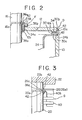
- the first auxiliary sealing member 30 is made of a plastically deformable metallic material such as Cu and is provided with a ring-shaped flange portion 30a and a short tubular-shaped projection 30b. As is best shown in Figure 2, the flange portion 30a of the first auxiliary sealing member 30 is disposed on the stepped portion 10a of the housing 10. The flange 24a of the first auxiliary shield 24a is provided between the stepped portion 10a of the housing 10 and the flange 30a of the first auxiliary sealing member 30. The projection 12b of the upper end plate 12 is disposed on the flange portion 30a of the first auxilary sealing member 30 via a metallized portion 34.
- Brazing material 42 is provided between the stepped portion 10a of the housing 10 and the flange 30a of the first auxiliary sealing member 30 and between the end of the housing 10 and the tubular portion 30b of the first auxiliary brazing member 30.
- the first sealing means D is comprised by the stepped portion 10a, the ring-shaped projection 12b of the upper end plate 12, the metallized portion 34 provided on the end surface of the projection 12b of the upper end plate 12 and brazing material 42.
- the second sealing means E comprises, similarly to the first connecting means D, the stepped portion 10b of the housing 10, the second auxiliary sealing member 32 provided in the stepped portion 10b of the housing 10, and the projection 14b of the lower end plate 14 fixed into the second auxiliary sealing member 32 via a metallized portion 34.
- the stationary contact rod 16 is made of Cu, and is inserted into the housing 10 through the aperture 12a of the upper end plate 12 and is secured to the upper end plate 12 by means of the first supporting means F.
- the first supporting means F comprises the aperture 12a of the upper end plate 12, a third auxiliary brazing member 38 having a tubular portion 38a and a flange portion 38b integrally formed with the tubular portion 38a, which is made of a plastically deformable material in the form of Cu, the upper end plate 12 made of the inorganic insulating material, a metallized portion 34 which is provided on an inner surface of the aperture 12a, and a clamping member in the form of a cover ring 36a fixed into an annular groove 16a of the stationary contact rod 16.
- the movable electrical contact 22 has a circular recess 22a, a ring-shaped slot 22b and a ring-shaped contact segment 22c fixed into the slot 22b.
- the movable contact rod 20 is inserted and fixed in the circular recess 22a of the movable electrical contact 22.
- the movable contact rod 20 is movably secured to the lower end plate 14 by means of the second supporting means G including bhe bellows 40 mounted on the movable contact rod 20, a clamping member in the form of a cover ring 36c fixed to an annular groove 20a of the movable contact rod 20 and brazing material 42.
- the upper end of the bellows 40 is secured to the movable contact rod 20.
- the lower end of the bellows is inserted into the aperture 14a of the lower end plate 14 and is secured to the lower end plate 14 by the metallized portion 34 provided on an inner surface of the aperture 14a and a brazing material 42.
- the shielding member C is made of a non-magnetic material in the form of an austentic stainless steel.
- the main arc-shield 23 comprises a circular flat portion 23a, a tubular portion 23b and an aperture 23c provided at the center portion of the flat portion 23a.
- the arc-shield 23 is inserted over the stationary contact rod 16 which passes through the aperture 23c and is fixed to a clamping member in the form of a cover ring 36b fixed to an annular slot 16b of the stationary contact rod 16 by means of the brazing material 42.
- the first auxiliary shield 24 comprises a tubular portion 24a and a flange portion 24b. The flange portion 24b of the first auxiliary shield 24 is secured to the stepped portion 10a of the housing 10.
- the first auxiliary shield 24 has a smaller diameter than that of the first main arc-shield 23 and is coaxially arranged with respect to the first main arc-shield 23.
- the second main arc-shield 26 of the shielding member C has a circular flat portion 26a, a tubular portion 26b and an aperture 26c provided at the center portion of the flat portion 26a.
- the arc-shield 26 is mounted on the movable contact rod 20 by the aperture 26c, cover ring 36c and brazing material 42.
- the second auxiliary shield 28 has a tubular portion 28a and a flange portion 28b which is secured to the stepped portion 10b of the housing 10.
- the housing 10 is made of a non-magnetic metallic material in the form of an austenitic stainless steel having high mechanical strength.
- Each of the upper and lower end plates 12 and 14 is made of inorganic insulating material such as an ceramics or a crystallized glass.
- Metallized portions 34 are made of metal alloy obtained by adding Mo or Mn to Ti (Mn-Ti alloy or Mo-Mn-Ti alloy) having the same coefficient of thermal expansion as that of the end plates 12 and 14, having a brazing temperature between 500°C and 1050°C.
- the stationary contact rod 16 and the movable contact rod 20 are made of Cu having a brazing temperature between 500°C and 1050°C.
- the electrical contacts 18 and 22 are made of Cu or of an alloy including Cu.
- the shielding member C is made of a non-magnetic material in the form of an austenitic stainless stel.
- the bellows 40 is made of an austenitic stainless steel.
- Each of the first auxiliary sealing member 30 and the second auxiliary sealing member 32 is made of a plastically deformable material in the form of Cu which is deformed by the thermal stress generated between the metallic housing 10 and the end plates 12 and 14 in slow cooling after brazing and which is employed to enhance the sealing connection between the metallic housing 10 and the upper and lower end plates 12 and 14 having different coefficients of thermal expansion from that of the housing 10.
- the auxiliary sealing members 30 and 32 can be made of Fe which is also deformed by thermal stress in cooling after brazing.
- the third auxiliary sealing member 38 is made of Cu which is also deformed by the thermal stress generated by the difference of the coefficient of thermal expansion between the upper end plate 12 and the stationary contact rod 16.
- the shielding member C can be made of Fe, which is inexpensive, when the vacuum interrupter is to be employed in a relatively low current and low voltage power system.
- the vacuum interrupter is constructed by the steps of disposing firstly the lower end plate 14 horizontally at the axial end of the housing 10 by means of brazing material, mounting the bellows 40 on the lower end plate 14 by means of brazing material 42 so that a tubular portion 40a is inserted into the aperture 14a of the lower end plate 14 by way of the metallized portion 34, fitting the second auxiliary sealing member 32 into projecting portion 14b of the lower end plate 14 by way of the metallized portion 34 and brazing material 42, disposing the flange portion 28b of the second auxiliary shield 28 by way of brazing material 42, fitting the stepped portion 10b of the housing 10 to the second auxiliary sealing member 32 by way of the flange 28b of the shield 28, surrounding the movable contact rod 20 at the upper end 40b of the bellows 40 by means of brazing material 42, supporting the movable contact rod 20 on the bellows 40 by means of the cover ring 36c, inserting the second main arc-shield 26 over the movable contact
- the following steps are further carried out: heating the brazing materials 42 which are inserted between the components of the vacuum interrupter at a brazing temperature which is between 900°C and 1050°C while evacuating at a pressure which is less than 1.333 mPa (10- 5 Torr). in a vacuum furnace, and letting gases induced by heating each component out of the vacuum interrupter.
- the heating temperature is high within the range of melting temperature of brazing material and the pressure is less than 1.333 mPa (10- 5 Torr).
- the temperature of the vacuum furnace is gradually decreased to room temperature and to allow plastic deformation of the auxiliary sealing members,
- the upper limit of the heating temperature for brazing is determined by the temperature of 1083° at which copper melts and the lowest heating temperature for brazing is determined by the temperature of 900°C required for brazing stainless steel.
- the brazing temperature may be less than 900°C if a Ni plating is provided on the brazing portions such as the housing 10 and the bellows 40 made of austenitic stainless steel.
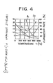
- Figure 4 shows the thermal characteristics of the tensile strength F and the elongation L of Cu and Fe, with respect to temperature T.
- a curve A 1 shows the tensile strength of Cu with respect to temperature
- a curve 8 1 designates the tensile strength of Fe with respect to temperature.
- a curve A 2 shows the elongation rate of Cu
- a curve B 2 shows the elongation rate of Fe with respect to temperature.
- the curves A i , 8 1 and A 2 , B 2 of Figure 4 the tensile strength of the material made of Cu decreases with the increase of temperature, and the elongation rate decreases and then increases with increase of temperature.
- the plastic deformation results from the thermal stress in brazing and thereby the sealing of the junctions of the envelope is achieved, the residual thermal stress being very small, because the tensile strengh of the auxiliary sealing members made of Cu or Fe are very small compared with those of the insulating end plates 12 and 14 made of the inorganic insulating materials such as ceramics or crystallized glass, when the auxiliary sealing members are brazed to the housing 10 and the end plates 12 and 14 at a high temperature greater than 900°C.
- the high sealing performance and the high mechanical strength of the envelope are obtained by employing the auxiliary sealing member made of Cu, Fe, in spite of the fact that the coefficients of thermal expansion of the end plates 12 and 14 made of inorganic insulating material in the form of ceramics differ from those of the housing 10 made of metallic material such as austenitic stainless steel. It is considered that a high sealing performance between the end plates 12 and 14 and the housing 10 obtained when the associated auxiliary sealing members are made of Fe, results from the coefficient of thermal expansion of the Fe being smaller than that of the Cu in spite of the fact that tensile strength of Fe with respect to temperature is larger than that of Cu as is shown in Figure 4 and that the creep strain rate of Fe is smaller than that of Cu, under a predetermined temperature. Further, a high sealing performance between the end plate 14 and the bellows 40 can be obtained due to the plastic deformation thereof, since the thickness of the bellows 40 is very small (about 0.1-0.2 mm).
- the following advantages can be achieved in the first embodiment of the vacuum interrupter according to the present invention: Since the auxiliary sealing members which are deformed due to the thermal stress generated in cooling after brazing are employed to connect the end plates made of insulating material to metallic material in the form of the housing and the stationary contact rod, the sealing performance of the interrupter is extremely enhanced by the aid of the auxiliary sealing members.
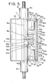
- Figure 5 shows a second vacuum interrupter embodying the present invention.
- the difference from the first embodiment described above resides in a shielding member C, the second sealing member E, the first securing means F and hermetic seal means G.
- the same reference numerals designated in Figure 1 through Figure 3 indicate corresponding parts of the vacuum interrupter and therefore a detailed description of the corresponding parts described above will be omitted.
- a first main arc-shield 44 has a disc-shaped flat portion 44a having approximately the same diameter as that of the stationary electrical contact 18, a tubular portion 44b formed integrally with the flat portion 44a and a curved portion 44c curved rectangularly from the outer edge of the flat portion 44a.
- the tubular portion of the first main arc-shield 44 is fitted to the stationary contact rod 16.
- a first auxiliary shield 46 has a circular flat portion 46a, a tubular portion 46b, a flange portion 46d and an aperture 46c provided in the center of the flat portion 46a.
- the flange portion 46d is secured to a stepped portion 10a of a housing 10.
- a second main arc-shield 48 comprises, similarly to the first main arc-shield 44, a circular flat portion 48a, a tubular portion 48b and a curved portion 48c.
- the tubular portion 48b is fitted to a movable contact rod 20.
- a second auxiliary shield 50 has a disc-shaped flat portion 50a, a tubular portion 50b and an aperture 50c provided at the center portion of the flat portion 50a.
- An open end of the shield 50 is secured to an internal surface of a lower end plate 14.
- a peripheral portion of an upper end plate 12 is disposed on the flange 46d of the shield 46 by means of brazing material.
- the diameter of the upper end plate 12 is smaller than the inner diameter of the stepped portion 10a of the housing 10.
- a first auxiliary sealing member 30 has a ring-shaped flat portion 30a and a short tubular portion 30b. The tubular portion 30b is fitted into the stepped portion 10a, and the upper end plate 12 is fitted into the auxiliary sealing member 30 to form the first connecting means E.
- a stationary contact rod 16 comprises an upper rod portion 16c and a lower rod portion 16d whose radius is smaller than that of the upper rod portion 16c.
- Brazing material 42 is inserted about the inner periphery of the upper end plate 12, and between the bottom of upper rod portion 16c and the upper end of the lower rod portion 16d.
- the lower rod portion 16d is inserted into the envelope A through the aperture 12a of the upper end plate 12 and the stationary contact rod 16 is supported on the end plate 12 by the upper rod portion 16c to form the first securing means F.
- the lower end of a bellows 40 is fixed to an inner surface of the lower end plate 14 by means of a metallized portion 34. Accordingly, the sealing performance is enhanced, because the mechanical strength of sealing is increased.
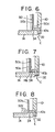
- FIG 6 through Figure 8 shows modifications of the shielding member C of the vacuum interrupter of Figure 5.
- a tubular portion 50b of a second auxiliary shield 50 is provided with a tapered portion 50d at an open end portion of the tubular portion 50b.
- a semi-circular annular slot 50e is provided on a surface of the tubular portion 50b of the second auxiliary shield 50.
- a plurality of axial slits 50f are provided on an open end of the tubular portion 50b of the shield 50. According to the shielding member C of Figure 8, thermal stress is eliminated in brazing the shield 50 to the lower end plate 14 by providing the slits 50f in the open end of the tubular portion 50b.
- FIG 9 shows a further modification of the vacuum interrupter of Figure 5.
- a second auxiliary shield 50 comprises a circular flat portion 50a, a tubular portion 50b formed integrally with the flat portion 50a, an aperture 50E provided at the center portion thereof and a flange portion 50g curved rectangularly with respect to the tubular portion 50b.
- the flange portion 50g is secured to a second auxiliary brazing member 32.
- the vacuum interrupter of the second embodiment is manufactured by similar steps to those of the manufacturing method of the vacuum interrupter of the first embodiment. Namely, a brazing material is firstly disposed between each component of the vacuum interrupter. Next, the vacuum interrupter previously assembled is located and inserted into a vacuum furnace and thereafter the vacuum interrupter is heated at the brazing temperature which is between 900°C and 1050°C while evacuating at a pressure which is less than 1.333 mPa (10- 5 Torr). After the brazing material inserted between the components has melted, the temperature of the vacuum furnace is gradually decreased to a predetermined temperature to allow plastic deformation of the auxiliary sealing members and the vacuum furnace is maintained at the predetermined temperature during the given time interval. The temperature of the vacuum furnace is further gradually decreased to room temperature. When the temperature has decreased to the room temperature, the respective components of the vacuum interrupter are securely and hermetically fixed each other.
- a third vacuum interrupter embodying the invention which is similar to the first and the second embodiments described above, in this third embodiment brazing is executed in two steps, and the difference from the embodiments described above resides in a shielding member, sealing means and securing means.
- a stepped portion 1 Oc is provided at the outer surface of one end of a housing 10.
- a stepped portion 10d is provided at the outer surface of the other end of the housing 10.
- a first auxiliary sealing member 30 formed with a tubular shape is fitted and secured by brazing to the stepped portion 10c.
- An upper end plate 12 is fitted into the first auxiliary sealing member 30 and is hermetically secured to the brazing member 42 by means of a metallic portion 34to form first sealing means D.
- a second auxiliary sealing member E formed with a tubular shape is fitted and secured by brazing to the stepped portion 10d of the housing 10.
- a lower end plate 14 is fitted into the second auxiliary sealing member 32 and is hermetically secured to the second auxiliary sealing member 32 by means of a metallized portion 34 to form second sealing means E.
- the upper end plate 12 is provided with an aperture 12a at the center portion thereof.
- a stationary contact rod 16 has an upper rod portion 16c and a lower rod portion 16d of which the diameter is smaller than that of the upper rod portion 16c.
- a third auxiliary sealing member 38 comprises a firsttubular portion 38a, a flat portion curved rectangularly from the first tubular portion 38a and a second tubular portion 38c which has a large diameter and is shorter than the first tubular portion 38a.
- the first tubular portion 38a of the third auxiliary sealing member 38 is fitted to the lower rod portion 16d of the stationary contact rod 16, and an open end of the second tubular portion 38c of the third auxiliary sealing member 38 is secured to an inner surface of the upper end plate 12 by means of a metallized portion 34 and brazing material to form the first supporting means F.
- the shielding member C comprises a cup-shaped first main arc-shield 23 mounted on the stationary contact rod 16, a tubular-shaped first auxiliary shield 24 fixed to an inner surface of the upper end plate 12 by means of a metallized portion 34, and brazing material, a second main arc-shield 26 mounted on a flange 20e of the movable contact rod 20 so as to be directed toward the lower end plate 14 and a tubular-shaped second auxiliary shield 28 fixed to an inner surface of the lower end plate 14 so as to be located coaxially with respect to the second main arc-shield 26. Since the auxiliary shields 24 and 28 are, respectively, secured to the end plates 12 and 14, the voltage potential is maintained at an intermediate value between that of the stationary contact rod 16 and that of the housing 10 and thereby the insulating strength within the envelope A is enhanced.
- Each component of the shielding member C is made of an austenitic stainless steel.
- the auxiliary shields 24 and 28 can also be made of Cu or Fe which is deformed by the thermal stress generated by brazing the auxiliary shield 24 and 28 to the end plates 12 and 14 and cooling gradually or can be made of Fe-Ni-Co alloy or Fe-Ni alloy which has approximately the same coefficient of thermal expansion as that of the inorganic material such as an alumina-ceramics material.
- the vacuum interrupter is constructed by the steps of supporting the upper end plate 12 horizontally such that the metallized portions 34 are directed toward the upper direction, disposing the first auxiliary shield 24 on the upper end plate 12 via the metallized portion 34, mounting the third auxiliary sealing member 38 on the upper end plate 12 by means of the metallized portion 34 and brazing material, inserting the stationary contact rod 16 from the lower direction into the first tubular portion of the third auxiliary sealing member 38, mounting the first main arc-shield 23 on the cover ring 36c which is fixed to an annular groove 16b of the stationary contact rod 16 by means of brazing material, and fixing a stationary electrical contact 18 to an end of the stationary contact rod 16.
- the following steps are then further effected:
- the lower end plate 14 is supported horizontally so that the metallized portions 34 is directed toward the upper direction and the second auxiliary shield 28 on the lower end plate 14 via the metallized portion 34.
- the lower end 40a of the bellows 40 is disposed on the lower end plate 14 by way of the metallized portion 34.
- the movable contact rod 20 is inserted from the upper side into the bellows 40 and is disposed on the upper end 40b of the bellows 40 by means of the flange 20e and thereafter brazing material is inserted between the upper end 40b and the flange 20e.
- the second main arc-shield 26 is inserted on the upper end portion of the movable contact rod 20 and is engaged with the flange 20e by means of brazing material.
- the movable electrical contact 22 is secured to a circular recess 22a of the movable electrical contact 22 by means of brazing material.
- a contact ring 22c is secured in a circular recess 22b of the movable electrical contact 22.
- auxiliary shields 24 and 28 of the shielding member C can be made of a plastically deformable metallic material such as Cu or Fe which is deformed in slow cooling and due to the thermal stress generated in brazing, or can be made of Fe-Ni-Co alloy or Fe-Ni alloy which has same coefficient of thermal expansion as that of the inorganic insulating material such as the ceramics.
- the steps are mounting the first auxiliary shield 24 on the upper end plates 12, inserting the third auxiliary sealing member 38 on the stationary contact rod 16, engaging the first main arc-shield 23 with the cover ring 36c, and supporting the stationary side after inserting the stationary contact rod 16 into the aperture 12a of the upper end plate 12.
- a leak test of the hermetically brazed stationary portion, the movable portion and the housing portion are carried out in order to confirm the sealing performance of the stationary and the movable portion.
- a second step of brazing is carried out in order to construct the vacuum interrupter.
- the brazing stated above is again carried out.
- a temporary assembly of the vacuum interrupter is carried out by fitting the stationary portion and the movable portion to the housing portion. The temporary assembly is heated at a temperature ranging from 500°C to 1050°C at a pressure less than 1.333 mPa (10- 5 Torr).
- each of said three portions is redegassed and then is brazed at high vacuum.
- the temperature of the vacuum furnace is decreased to a predetermined temperature to allow plastic deformation of the auxiliary sealing members and the auxiliary shields and is kept during a predetermined time internal at the deformation temperature.
- the temperature of the vacuum furnace is further decreased from said deformation temperature to room temperature.
- each of the auxiliary sealing members is brazed to the metallic housing 10 at the first step of brazing in accordance with the manufacturing method described above, it is possible to braze the auxiliary sealing members to the end plates in the first step of brazing. Further, it is possible to carry out the brazing of the stationary portion and the movable portion in the first step of brazing and thereafter to insert the auxiliary sealing members between the metallic housing and the end plates in a previous assembling step which is carried out prior to the second step of brazing.
- FIG 11 shows a fourth vacuum interrupter embodying the present invention.
- the interrupter of this embodiment is characterized in that an evacuated envelope A comprises a housing 10 made of a non-magnetic material such as an austenitic stainless steel, disc-shaped end plates 12 and 14 made of an inorganic insulating material such as a ceramic or crystallized glass secured to end portions of the housing by way of auxiliary sealing members.
- a non-magnetic material such as an austenitic stainless steel
- disc-shaped end plates 12 and 14 made of an inorganic insulating material such as a ceramic or crystallized glass secured to end portions of the housing by way of auxiliary sealing members.
- first sealing meuns D comprises a first auxiliary sealing member 30 connected to the housing 10 and the periphery of an upper end plate 12.
- Second sealing means E includes a second auxiliary sealing member 32, of the same material as the first auxiliary sealing member 30, connected to the housing 10 and the periphery of a lower end plate 14.
- the first auxiliary sealing member 30 comprises a first tubular portion 30b, the outer diameter of which is the same as that of the housing 10, a first flange portion 30a, a second tubular portion 30c formed integrally with the first flange portion 30a and a second flange portion 30d formed integrally with the second tubular portion 30c.
- the first tubular portion 30b is fixed to an end of the housing 10.
- the peripheral surface of the upper end plate 12 is fitted into the first tubular portion 30b of the first auxiliary sealing member 30, sandwiching a metallized portion 34 therebetween.
- the second sealing means E includes a second auxiliary sealing member 32 having a first tubular portion 32b, a first flange portion 32a, a second tubular portion 32c formed integrally with the first tubular portion 32b by way of the first flange 32a, a second flange 32d, and a third tubular portion 32e formed integrally with the second tubular portion by way of the second flange 32d.
- a shielding member C includes a first curved auxiliary shield 52 secured to the second flange 30d of the first auxiliary sealing member 30 and a second auxiliary shield 54 which is secured to the second flange 32c and the third tubular portion 32e of the second auxiliary sealing member 32.
- Figure 12 shows a modification of the vacuum interrupter of Figure 11.
- a first auxiliary sealing member 30 of the first sealing means D comprises a first tubular portion 30b and a second tubular portion 30f of diameter smaller than that of the first tubular portion 30b and formed integrally with the first tubular portion by way of a flange portion 30a.
- the first anular portion 30b is fitted into the housing 10 and secured to the inner surface of the housing by means of brazing.
- the peripheral surface of an upper end plate 12 is fitted into the second tubular portion 30f and secured by means of brazing to form the first sealing means D.
- a second sealing means E includes a second auxiliary sealing member 32 having a first tubular portion 32b, a flange portion 32a, and a second tubular portion 32f formed integrally with the first tubular portion 32b via a flange portion 32a, and is secured similarly to the first sealing means D.
- FIGS 13 through 15 show further modifications of the vacuum interrupter of Figure 11.
- a first auxiliary sealing member 30 includes a flange portion 30a, a first tubular portion 30b, a second flange 30g and a second tubular portion 30f, all which are formed integrally.
- the first tubular portion 30b fits sealingly within the housing 10, and second flange 30g is secured on an end of the housing 10.
- An upper end plate 12 is fitted into the second tubular portion 30f, sandwiching therebetween a metallized portion 34, to form the first sealing means D.
- a second sealing means E includes a second auxiliary sealing member 32 formed similarly to the first auxiliary sealing member 30 and is constructed similarly to the first sealing means D.
- a first tubular auxiliary sealing member 30 is secured to an outer stepped portion 10c of the housing 10, and an upper end plate 12 fits sealingly within the first tubular auxiliary sealing member 30 and is fixed to an end of the housing 10.
- Second sealing means E comprises a second tubular auxiliary sealing member 32 secured to an outer stepped portion 10d, and a lower end plate 14 fitted sealingly within the second tubular auxiliary sealing member 32 and fixed to an end of the housing 10.
- a first auxiliary sealing member 30 has a flange 30a and a tubular portion 30b.
- the inner end of the flange 30a is secured to an outer stepped portion 10c of the housing 10, and an upper end plate 12 is fitted into and secured to the tubular portion 30b sandwiching therebetween a metallized portion 34, to form first sealing means D.
- Second sealing means E includes a second auxiliary sealing member 32 which comprises a flange 32a and a tubular portion 32b, and which is formed as described for the first sealing means D.
- FIG 16 shows a fifth vacuum interrupter embodying the present invention.
- the vacuum interrupter of this embodiment is characterized in that auxiliary sealing members are secured hermetically to both end portions of a metallic housing and are further secured to insulating end plates hermetically.
- a first auxiliary sealing member 30 comprises a first flange portion 30a, a first tubular portion 30b connected to the outer edge of the first flange 30a, a second flange 30g formed perpendicularly with respect to the first tubular portion 30b, and a second tubular portion 30c connected to the second flange 30g.
- An end of a metallic housing 10 is secured to the first flange 30a.
- a first supporting means F includes a U-shaped third auxiliary sealing member 38 for sealingly connecting a stationary contact rod 16 to an inner surface of the upper end plate 12.
- a shielding member C includes a first curved auxiliary shield 52 which is secured to a second tubular portion 30c of the first auxiliary sealing member 30 by means of spot welding, and a second curved auxiliary shield 54 which is secured to a second tubular portion 32e of the second auxiliary sealing member 32 by means of spot welding.
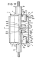
- Figure 17 shows a modification of the vacuum interrupter of Figure 16.
- the differences between the vacuum interrupter of Figure 17 and the vacuum interrupter of Figure 16 reside in the shape of an auxiliary sealing member for aiding the positioning of auxiliary shields.
- a first auxiliary sealing member 30 has a ring-shaped flange 30a and a curved portion 30c curved inwardly and formed integrally with the flange 30a.
- An end of a housing 10 is secured to the flange 30a of the first auxiliary sealing member 30, and an end 30b of the curved portion 30c is secured to an end surface of a ring-shaped projection 12b of an upper end plate 12 by means of a metallized portion 34 secured by brazing to form the first sealing means D.
- a second auxiliary sealing member 32 comprises a ring-shaped flange 32a and a curved portion 32c curved inwardly and formed integrally with the flange 32a.
- the flange 32a is, similar to the first auxiliary sealing member 30, secured to an end of the housing 10 and an end 32b of the curved portion 32c of the second auxiliary sealing member 32 is secured to an end of a ring-shaped projection 14b of a lower end plate 14 by means of brazing so that the lower end plate 14 is spaced apart from the housing 10, in order to form second sealing means E.
- a shielding member C includes a first auxiliary shield 52 which is curved inwardly and a second auxiliary shield 54 curved inwardly.
- One end of the shield 52 is fixed to the inner surface of the tubular portion 30b of the first auxiliary sealing member 30 by brazing or spot welding.
- One end of the shield 54 is secured to the inner surface of the tubular portion 32b of the second sealing member 32 by brazing or spot welding.
- FIG 18 shows a sixth vacuum interrupter embodying the present invention.
- auxiliary sealing members are provided with at least one curved portion for absorbing the mechanical stress generated by operation of the vacuum interrupter or by thermal stress during brazing.
- One end of the auxiliary sealing member is secured to an end portion of the housing by means of brazing, and other end of the auxiliary sealing member is fastened to an end plate.
- a cylindrical housing 10 is made of a non-magnetic metallic material such as an austenitic stainless steel of which the mechanical strength is relatively large.
- the housing 10 has a flange 10e curved toward the axis of the housing 10.
- a first auxiliary sealing member 30 comprises a flange portion 30a, a tubular portion 30b curved at right angles with respect to the flange portion 30a, and a curved portion 30h curved into a semi-circular shape.
- One end of the housing 10 is inserted into the tubular portion 30b of the first auxiliary sealing member 30.
- One end of the curved portion 30h is secured to the end of a projection 12b provided on the rim of an upper end plate 12, sandwiching a metallized portion 34 therebetween.
- the first sealing means D comprises the first auxiliary sealing member 30 having the flange portion 30a, the first tubular portion 30b extending at right angles and the semi-circular curved portion 30h, the end of the housing 10, which is inserted into the tubular portion 30b of the first auxiliary sealing member 30, and the rim of the upper end plate 12 to which the end of the curved portion 30h of the first auxiliary sealing member 30 is secured.
- the second sealing means E comprises an end of the housing 10, a second auxiliary sealing member 32 having a ring-shaped flange portion 32a, a tubular portion 32b having a diameter smaller than that of the flange portion 32a, and a curved portion 32h formed integrally with the flange portion 32a and the tubular portion 32b, and an end of a projection 14b which is secured to an end of the tubular portion 32b of the second auxiliary sealing member 32.
- First supporting means for supporting and securing hermetically a stationary contact rod includes a cup-shaped third auxiliary sealing member 38 and a ring-shaped metallized portion 34 provided on an upper surface of the upper end plate 12.
- One end of the third auxiliary sealing member 38 is fixed to a lower rod portion 16d of the stationary contact rod 16.
- the other rod of the auxiliary sealing member 38 is secured to the upper surface of the upper end plate 12 by means of the metallized portion 34 to support the stationary contact rod 16.
- Each of the auxiliary sealing members is made of a metal, such as Cu or Fe which is deformed by the thermal stress generated by slow cooling after brazing.
- a shielding member C comprises a first main arc-shield 56 mounted on the stationary contact rod 16, a first auxiliary shield 58 provided coaxially with respect to the first main arc-shield 56, a second main arc-shield 60 mounted on a movable contact rod 20 and a second auxiliary shield 62 provided coaxially with respect to the second main arc-shield 60.
- the first main arc-shield 56 comprises a first tubular portion 56a fixed to the lower rod portion 16d and secured to a stationary electrical contact 18, a ring-shaped flat portion 56b formed integrally with the first tubular portion 56a and a second tubular portion 56c formed integrallywith the flat portion 56b and directed toward the upper end plate.
- the second main arc-shield 60 is formed by a first tubular portion 60a fitted to the movable contact rod 20 and fastened to a movable electrical contact 22, a ring-shaped flat portion 60b formed integrally with the first annular portion 60a and a second annular portion 60c formed integrally with the flat portion 60b and directed toward the lower end plate 14.
- the first auxiliary shield 58 includes a first tubular portion 58a having an outer diameter smaller than that of the first main arc-shield, a first flange portion 58b extending outwards from the first tubular portion 58a, a second tubular portion 58c formed integrally with an outer edge of the first flange portion 58b, a second flange portion 58d extending outwards from the second tubular portion 58c and having an outer diameter larger than that of the flange 10e of the housing 10 and a tubular projection 58e projecting from the outer edge of the second flange portion 58d.
- the second tubular portion 58c of the first auxiliary shield 58 is mounted on the housing 10 by inserting the second tubular portion 58c into the flange 10e of the housing 10 and engaging the second flange portion 58d with the outer surface of the flange 10e of the housing 10.
- the upper end plate 12 fits into the corner between the second flange portion 58d and the projection 58e of the second auxiliary shield 58.
- the second auxiliary shield 62 has a first portion 62a having a smaller diameter than that of the second main arc-shield 60 and being coaxially located with the second main arc-shield 60, a flange portion 62b extending outwards from the first tubular portion 62a and a second tubular portion 62c formed integrally with the flange 62b.
- the second tubular portion 62c is inserted into the tubular portion 32c of the second auxiliary sealing member 32 and is secured to the tubular portion 32c of the second auxiliary sealing member 32 by means of spot welding.
- the shielding member C is made of an austenitic stainless steel.
- each of the auxiliary sealing members is provided with at least one curved portion, the impact force applied to the housing during operation of the vacuum interrupter is absorbed by the curved portion of the auxiliary member; similarly, thermal stress is absorbed by the curved portion. Since mechanical stress and thermal stress are eliminated, the diameter of the housing can be increased inexpensively and easily.
- Figure 19 designates a modification of the interrupter of Figure 18.
- a shielding member C includes an approximately disc-shaped first auxiliary shield 64 having an inner curved portion 64a which has a smaller diameter than that of the flange 10e of housing 10.
- the first auxiliary shield 64 is made of an austenitic stainless steel and is fixed to the flange portion 10e by brazing.
- the second auxiliary shield 28 has a ring-shaped flange portion 28b affixed to a second auxiliary sealing member 32 of second sealing means E.
- the second auxiliary sealing member 32 of the second sealing means E has a flange portion 32a, a first tubular portion 32b formed integrally with the flange portion 32a and a circular projection 32g projecting from the outer edge of the flange portion 32a and having a larger diameter than the housing 10.
- One end of the tubular portion 32b is affixed to the upper surface of a lower end plate 14 by means of a metallized portion 34.
- An end of the housing 10 is secured to the flange portion 32a of the second auxiliary sealing member 32 to form the second sealing means E.
- Second supporting means G comprises a bellows 40.
- the upper end 40b of which is secured to a movable contact rod 20 and the lower end 40a of which is inserted into an aperture 14a provided in the central portion of the disc-shaped lower end plate 14 and brazed to a fourth auxiliary sealing member 66 located in the aperture 14a.
- the fourth auxiliary sealing member 66 is made of a metallic material such as Cu or Fe and is U-shaped.
- An end of the fourth auxiliary sealing member 66 is secured to a metallized portion 34 provided on a ring-shaped projection, which projection is fixed on the inner surface of the lower end plate 14 near the aperture 14a by brazing.
- the vacuum interrupter shown in Figure 19 the same advantages as those of Figure 18 can be achieved.
- Figure 20 shows a seventh vacuum interrupter embodying the present invention.
- ring-shaped metallized portions 34 are provided on the central and peripheral projections 12c and 12b of the outside surface of an upper end plate 12 and on the central and peripheral projections 14c and 14b of the inside surface of a lower end plate 14.
- a first auxiliary sealing member 30 is fitted to the upper end plate 12 so that a flange portion 30a engages with the projection 12b formed in an edge portion of the upper end plate by way of the metallized portion 34 and a tubular portion 30b is fitted to the outer edge surface of the upper end plate 12.
- the tubular portion 30b of the first auxiliary sealing member 30 is fitted and secured to a stepped portion 10a of a housing 10 to form a first sealing means D.
- a second auxiliary sealing member 32 is fitted and secured to the lower end plate 14 such that a flange portion 32a engages with the projection 14b of the lower end plate 14 by way of the metallized portion 34 and a tubular portion 32b is fitted to the outer edge surface of the lower end plate 14.
- the tubular portion 32b of the second auxiliary sealing member 32 is fitted and secured to a stepped portion 10b of the housing to form the second sealing means E.
- FIG. 21 shows an eighth vacuum interrupter embodying the present invention.
- a part of a shielding member C is made of a metallic material which is plastically deformed by the thermal stress generated in cooling after brazing and is employed in an auxiliary sealing member to aid sealing between the metallic housing and the insulating end plates.
- the shielding member C comprises a first main arc-shield 23 mounted on a stationary contact rod 16, a first auxiliary shield 70, a second main arc-shield 26 mounted on a movable contact rod 20 and a second auxiliary shield 72.
- the first auxiliary shield 70 is made of a metallic material, such as Cu or Fe, which is plastically deformed by thermal stress in slow cooling after brazing.
- the first auxiliary shield 70 comprises a tubular portion 70a and a flange portion 70b extending outwards from the tubular portion 70a.
- One end of the flange portion 70b of the first auxiliary shield 70 is disposed between a stepped portion 10a of a housing 10 and an upper end plate 12 to be employed as a first auxiliary sealing member 30 of first sealing means D.
- the second shield 72 is made of the same material as that of the first auxiliary shield 70.
- the second auxiliary shield 72 is formed by a tubular portion 72a and a flange portion 72b outwardly extending from the tubular portion 72a.
- An end portion of the flange portion 72b is fitted between a stepped portion 10b of the housing 10 and a lower end plate 14 and is also employed as a second auxiliary sealing member 32 of second sealing means E.
- the number of elements of the vacuum interrupter is reduced and thereby the construction of the vacuum interrupter is simplified, since a part of element of the shielding member C is made of a metallic material such as Cu or Fe which is plastically deformed by thermal stress in cooling after brazing and is employed as the auxiliary sealing member for aiding the sealing of the vacuum interrupter. It is easy to position the auxiliary shield in the envelope, because the auxiliary shields are fitted between the end plates and the end portions of the housing.
- the stepped portions are provided in order to secure the shields in the embodiment stated above, the stepped portions may be omitted and stepped portions may be provided on end portions of the shields in order to secure the shields.
Landscapes
- High-Tension Arc-Extinguishing Switches Without Spraying Means (AREA)
Description
- The present invention relates to a vacuum interrupter and, more particularly, a vacuum interrupter manufactured by using a suitable metallic auxiliary sealing material.
- Vacuum circuit interrupters are, generally, constructed by a highly evacuated envelope, a stationary electrical contact provided in the envelope, a movable electrical contact provided in the envelope so us to be opposite to the stationary electrical contact and shields. The envelope comprises, substantially, a tubular housing, a pair of end plates. The housing is, generally, fabricated by a cylindrical insulating material, and a pair of metallic end plates used to form the evacuated envelope.
- Moreover, the vacuum interrupter is, generally, constructed by the steps of fixing an upper end and a lower end plates to each axial end of a cylindrical insulating housing respectively, mounting a bellows on the lower end plate, inserting a movable contact rod into the bellows, securing a movable electrical contact on the movable contact rod, and incorporating a stationary contact rod having a stationary electrical contact at the bottom thereof to the upper end plate.
- In this conventional vacuum interrupter, it is difficult to make the diameter of the envelope large because the envelope is very expensive when a large diameter housing made of glass or ceramics is used as a part of the envelope. Further, material made of an alloy Fe-Ni-Co or an alloy of Fe-Ni is usually employed to provide a vacuum-tight-seal. This vacuum tight-seal is also very expensive as well as having magnetic properties. The vacuum interrupter, therefore, becomes very expensive and of low reliability because the temperature thereof rises due to the eddy current generated by high current flow of the contact rods.
- US-A-3 674958 discloses a vacuum type circuit interrupter which comprises a hollow constant-diameter cylindrical metallic envelope, preferably fabricated of copper, which is provided with integrally formed annular shoulders inside the envelope near its end openings. Stationary and movable contact rods extend into the envelope through the end openings and have contacts brazed to their inner ends. The rods are provided with integrally formed shoulders against which circular or disk-type shields are secured as by brazing. A toroidally shaped substantially flat, preferably high-grade ceramic, insulating member or end plate is disposed at one end opening of the envelope and accommodates the stationary contact rod. A toroidally shaped substantially cylindrical, preferably high-grade ceramic, insulating member or end tube is disposed at the other end opening of the envelope and accommodates the movable contact rod and a flexible sealing means such as a bellows. A first metallic sealing member or ring is joined or sealed at its edges as by welding between one of the annular shoulders of the envelope and the outer peripheral edge of the insulating end plate. Preferably, the sealing member is fabricated of thin Kovar metal or other material having thermal expansion and contraction characteristics similar to the ceramic material of the end plate. A second metallic sealing member or ring in tubular form and of the same composition as the first sealing member is joined or sealed at its edges as by brazing between an opening in the insulating end plate and a shoulder provided on the stationary contact rod. A third metallic sealing member or ring is joined or sealed at its edges as by welding between the other of the annular shoulders of the envelope and the surface of the ceramic end tube.
- It is an object of the present invention to provide a highly reliable and high performance vacuum interrupter.
- The present invention provides a vacuum circuit interrupter comprising:
- a) an evacuated envelope consisting essentially of a cylindrical metal housing, upper and lower electrically insulating end plates secured to the housing by first and second auxiliary sealing members of first and second sealing means, a stationary contact rod, a movable contact rod, and a metal bellow;
- b) the upper and lower end plates closing opposite ends of the cylindrical metal housing, each of the upper and lower end plates having a coaxial central aperture;
- c) the stationary contact rod coaxially entering the envelope through the central aperture of the upper and plate, the stationary contact rod being fixed to the upper end plate in such a manner as to provide a hermetic seal therewith;
- d) the movable contact rod coaxially and movably entering the envelope through the central aperture of the lower end plate without impairing the vacuum within the envelope;
- e) stationary and movable electrodes respectively connected to an inner end of the stationary and movable rods in such a manner as to engage each other via an electrical contact portion when the movable rod moves toward the stationary contact rod and disengage from each other when the movable contact rod moves away from the stationary contact rod; and
- f) opposite ends of the bellows being respectively fixed to the movable contact rod and to the lower end plate in such a manner as to provide a hermetic seal about the movable contact rod to allow for movement of the movable contact rod without impairing the vacuum within the envelope; characterized in that
- said upper and lower end plates have coefficients of thermal expansion differing from that of said housing,
- said first and second auxiliary sealing members have coefficients of thermal expansion differing from those of said upper and lower end plates,
- said first and second auxiliary sealing members are made of a plastically deformable metallic material, each of which is plastically deformed by thermal stresses generated in a slow cooling process after vacuum brazing, whereby said upper and lower end plates (12,14) are secured to said housing (10) by means of said first and second auxiliary sealing members (30, 32) in a slow cooling process after vacuum brazing.
- An advantage offered by the invention is that by constructing an envelope by employing a housing made of a non-magnetic metallic material, end plates of insulating materials in the form of a ceramics or crystallized glass and auxiliary sealing members made of metallic materials which are deformable due to the thermal stress at the high temperature, it is possible to provide a vacuum power interrupter of which a diameter can be easily and inexpensively made large in order to enhance the performance of the vacuum power interrupter.
- The invention also provides a method of manufacturing a vacuum interrupter comprising the steps of:
- (a) inserting one end of a bellows made of an austenitic stainless steel into an aperture in the center of a disc-shaped lower insulating end plate,
- (b) disposing a second auxiliary metal sealing member on an outer circumferential edge of said lower end plate,
- (c) disposing a second auxiliary metal shield on said second auxiliary sealing member,
- (d) inserting a movable contact rod through said aperture of the lower end plate and the other end of said bellows,
- (e) setting a second main metal shield on the outer peripheral surface of said rod and fixing a movable contact to an inner end of said rod,
- (f) fixing a contact ring to said movable contact,
- (g) disposing a stationary contact on said contact ring and fixing a stationary contact rod to said contact,
- (h) setting a first main metal shield on the outer peripheral surface of said rod,
- (i) disposing one end of a metal housing on said second auxiliary metal shield and a first auxiliary shield on the other end of said housing,
- (j) disposing a first auxiliary sealing metal member on said shield and disposing an outer circumferential end of an upper insulating end plate having a central aperture on said sealing member,
- (k). inserting a third auxiliary sealing metal member between said stationary contact rod and said aperture of said end plate,
- (I) disposing brazing material at points of contact between the members making up the vacuum interrupter so as to complete temporary assembly of the vacuum interrupter,
said method of constructing the vacuum interrupter characterized by the further steps of - (m) forming a vacuum envelope by brazing hermetically said temporary assembly of the vacuum interrupter by means of heating and degassing in a vacuum environment at less than 1.333 mPa (10-5 Torr) at a temperature between 900°C and 1050°C,
- (n) and plastically deforming said first, second umd third auxiliary sealing members by cooling said vacuum environment to a room temperature.
- The invention also provides a method of constructing a vacuum interrupter comprising the steps of
- (a) disposing one end of a bellows made of an austenitic stainless steel on an inner surface of a disc-shaped lower insulating end plate in the vicinity of an aperture in the center of said lower end plate,
- (b) setting a second auxiliary shield on an inner surface of sid lower end plate so that the second auxiliary shield is electrically insulated from the movable contact rod and the housing,
- (c) inserting a movable contact rod having a second main arc-shield mounted on the outer surface thereof through said aperture in the lower end plate,
- (d) fixing a movable contact to an inner end of said movable contact rod,
- (e) fixing a contact ring to said movable contact,
- (f) disposing brazing material at points of contact between members making up said vacuum interrupter, thereby completing temporary assembly of a movable portion of the vacuum interrupter,
- (g) setting a first auxiliary shield on an inner surface of the upper end plate so that the first auxiliary shield is electrically insulated from the stationary contact rod and the housing,
- (h) providing a third auxiliary sealing member on a disc-shaped upper end plate so as to be adjacent to an aperture in the center of said upper end plate,
- (i) inserting a stationary contact rod having a first main arc-shield mounted on its outer peripheral surface through said third auxiliary sealing member,
- (j) fixing a stationary contact to an inner end of sid stationary contact rod,
- (k) disposing brazing material at points of contact between members making up said vacuum interrupter, thereby completing temporary assembly of a stationary portion of the vacuum interrupter,
- (I) inserting a first and second auxiliary sealing members into opposite ends of a housing so as to sandwich brazing material therebetween, thereby completing temporary assembly of a housing portion of the vacuum interrupter,
said method of constructing the vacuum interrupter characterized by comprising the further steps of: - (m) brazing said previously assembled movable portion, stationary portion and housing portion by means of heating and degassing in a reducing atmosphere or in a vacuum environment at less than 1.333 mPa (10-5 Torr) at a temperature between 900°C and 1050°C,
- (n) plastically deforming said first, second and third auxiliary sealing members by cooling said vacuum or reducing environment to room temperature,
said method of constructing the vacuum interrupter further characterized by the steps of: - (o) disposing one end of said housing portion on an outer peripheral portion of said lower end plate of said movable portion and disposing an outer peripheral portion of said upper end plate of said stationary portion, on the other end of said housing portion, thereby completing temporary assembly of the vacuum interrupter,
- (p) forming a vacuum envelope by brazing hermetically said temporary assembly of the vacuum interrupter by means of reheating and redegassing in a vacuum environment at less than 1.333 mPa (10-5 Torr) at a temperature between 500°C and 1050°C,
- (q) and plastically deforming said first, second and third auxiliary sealing members by cooling said vacuum environment to room temperature.
- Ways of carrying out the invention are described in detail below with reference to drawings which illustrate several specific embodiments, in which:-
- Figure 1 is a cross sectional view through a first vacuum interrupter constructed in accordance with the invention.
- Figure 2 is an enlarged view of part of the interrupter of Figure 1.
- Figure 3 is an enlarged view of another part of the interrupter of Figure 1.
- Figure 4 is a graph showing characteristics of metallic materials employed in the vacuum interrupter of the present invention.
- Figure 5 is a fragmental sectioned view of another vacuum interrupter constructed in accordance with the present invention.
- Figure 6 is an enlarged view of part of a modification of the interrupter shown in Figure 5.
- Figure 7 is an enlarged view of part of another modification of the interrupter shown in Figure 5.
- Figure 8 is an enlarged view of a partial portion of further modification of the interrupter shown in Figure 5.
- Figure 9 is a fragmental sectioned elevational view of a modification of the interrupter of Figure 5.
- Figure 10 is a fragmental sectioned elevational view showing another embodiment of the present invention.
- Figure 11 is a fragmental sectioned view of another embodiment of a vacuum interrupter accordigg to the present invention.
- Figure 12 is a fragmental sectioned view of a further embodiment of a vacuum interrupter according to the present invention.
- Figure 13 is a cross sectioned view of part of a modification of the interrupter of Figure 12.
- Figure 14 is a cross sectioned view of another modification of the vacuum interrupter of Figure 12.
- Figure 15 is a cross sectioned view of a further modification of the vacuum interrupter of Figure 12.
- Figure 16 is a fragmental sectioned view of another embodiment of a vacuum interrupter according to the present invention.
- Figure 17 is a fragmental sectioned view of a modification of the vacuum interrupter of figure 16.
- Figure 18 is a fragmental sectioned view of another embodiment of a vacuum interrupter according to the present invention.
- Figure 19 is a fragmental sectioned view of a modification of the vacuum interrupter of Figure 18.
- Figure 20 is a fragmental sectioned view of another embodiment of a vacuum interrupter according to the present invention.
- Figure 21 is a fragmental sectioned view or a further embodiment of a vacuum interrupter according to the present invention.
- Referring to the drawings, particularly to Figures 1 to 3, there is shown as first embodiment a vacuum interrupter in accordance with the present invention. The vacuum interrupter comprises, substantially, an evacuated envelope A including a
cylindrical housing 10 made of a non-magnetic material in the form of an austenitic stainless steel, anupper end plate 12 and alower end plate 14, both of which are made of inorganic materials such as alumina ceramics or crystallized glass, an electrical contact member B including astationary contact rod 16 supported by theupper end plate 12, a stationaryelectrical contact 18 secured to thestationary contact rod 16, amovable contact rod 20 supported by thelower end plate 14, a movableelectrical contact 22 secured to themovable contact rod 20, and a shielding member C for shielding the internal surface of theend plates - The vacuum interrupter further comprises first sealing meuns D for sealing hermetically the
upper end plate 12 to thehousing 10, second sealing means E for sealing hermetically thelower end plate 14, first supporting means F for supporting and securing hermetically thestationary contact rod 16 on theupper end plate 12, and hermetic seal means G for sealing movably and hermetically themovable contact rod 20 on thelower end plate 14. - As is shown in Figure 1, the
upper end plate 12 is secured to one end of thehousing 10, and thelower end plate 14 is secured to other end of thehousing 10 to form the envelope A. In the electrical contact member B, the stationaryelectrical contact 18 has acircular recess 18a provided in the center portion thereof. An end portion of the stationary contact rod is inserted and secured to therecess 18a. The movableelectrical contact 22 is provided with acircular recess 22a in the center portion thereof and a ring-shapedslot 22b on the surface opposed to the stationaryelectrical contact 18. An end portion of themovable contact rod 20 is inserted in and secured to therecess 18a, and anelectrical contact ring 22c is disposed on theslot 22b to form the contact member B. - The shielding member C comprises a first main arc-
shield 23 mounted on thestationary contact rod 16, a firstauxiliary shield 24 secured on theupper end plate 12, a second main arc-shield 26 mounted on themovable contact rod 20 and a secondauxiliary shield 28 secured to thelower end plate 14. - In more detail, axial and circular stepped
portions housing 10. A first auxiliary sealing member30 is fitted between thehousing 10 and theupper end plate 12. A secondauxiliary sealing member 32 is provided between thehousing 10 and thelower end plate 14. The firstauxiliary sealing member 30 has a ring-shapedflat portion 30a and atubular portion 30b formed in one piece with theflat portion 30a. The secondauxiliary sealing membr 32 has also a ring-shapedflat portion 32a and atubular portion 32b formed in one piece with theflat portion 32b. Theupper end plate 12 has anaperture 12a provided in the center portion thereof and atubular portion 12b formed at the peripheral edge portion thereof. Thelower end plate 14 has anaperture 14a provided in the center portion thereof and atubular portion 14b formed at the peripheral edge portion thereof. - As is shown in Figures 1 and 2, first sealing means D comprises the stepped
portion 10a of thehousing 10, the firstauxiliary sealing member 30 fitted in the steppedportion 10a of thehousing 10, and theupper end plate 12 disposed on theauxiliary sealing member 30 by means of a metallizedportion 34 provided on an end of thetubular portion 12b of theupper end plate 12. The second sealing means E comprises the steppedportion 10b of thehousing 10, the secondauxiliary sealing member 32 fitted in the steppedportion 10b of thehousing 10, and thelower end plate 14 fitted in theauxiliary brazing member 32 by means of a metallizedportion 34 provided on an end of the tubular portion of thelower end plate 14. - As is shown in Figures 1 and 2, a
clip ring 36a is fitted into anannular slot 16a provided on the circumferential surface of thestationary contact rod 16. Thestationary contact rod 16 is inserted into thehousing 10 through a thirdauxiliary sealing member 38. The thirdauxiliary sealing member 38 is provided with atubular portion 38a and aflange portion 38b. A metallizedportion 34 is provided on the inner surface of theaperture 12a of theupper end plate 12. Thetubular portion 38a of the thirdauxiliary sealing member 38 is inserted into theaperture 12a by way of the metallizedportion 34. Accordingly, the first supporting means F comprises theclip ring 36a and the thirdauxiliary sealing member 38. - As is shown in Figures 1 and 3, the
movable contact rod 20 is inserted into a bellows 40. Theupper end 40b of thebellows 40 is secured in vacuum-tight seal by means of brazingmaterial 42. The lower end of thebellows 40 is inserted into theaperture 14a of thelower end plate 14 and is secured in vacuum-tight seal by means of a metallizedportion 34 andbrazing material 42 to form the hermetic seal means G. - In more detail, the
cylindrical housing 10 of the envelope A is made of an non-magnetic metallic material in the form of austenitic stainless steel which has high mechanical strength. Both open end portions of thehousing 10 are provided with axial steppedportions housing 10. Theupper end plate 12 is made of an inorganic insulating material in the form of ceramics or crystallized glass and has a ring-shapedprojection 12b projecting toward the inner side of theenvelope 10. Thelower end plate 14 is made of an inorganic insulating material such as ceramics or crystallized glass and has a ring-shapedprojection 14b at the edge portion thereof and projecting toward the inner side of theenvelope 10. The firstauxiliary sealing member 30 is made of a plastically deformable metallic material such as Cu and is provided with a ring-shapedflange portion 30a and a short tubular-shapedprojection 30b. As is best shown in Figure 2, theflange portion 30a of the firstauxiliary sealing member 30 is disposed on the steppedportion 10a of thehousing 10. The flange 24a of the first auxiliary shield 24a is provided between the steppedportion 10a of thehousing 10 and theflange 30a of the firstauxiliary sealing member 30. Theprojection 12b of theupper end plate 12 is disposed on theflange portion 30a of the firstauxilary sealing member 30 via a metallizedportion 34.Brazing material 42 is provided between the steppedportion 10a of thehousing 10 and theflange 30a of the firstauxiliary sealing member 30 and between the end of thehousing 10 and thetubular portion 30b of the firstauxiliary brazing member 30. Accordingly, the first sealing means D is comprised by the steppedportion 10a, the ring-shapedprojection 12b of theupper end plate 12, the metallizedportion 34 provided on the end surface of theprojection 12b of theupper end plate 12 andbrazing material 42. - As is shown in Figure 1, the second sealing means E comprises, similarly to the first connecting means D, the stepped
portion 10b of thehousing 10, the secondauxiliary sealing member 32 provided in the steppedportion 10b of thehousing 10, and theprojection 14b of thelower end plate 14 fixed into the secondauxiliary sealing member 32 via a metallizedportion 34. - As is best shown in Figures 1 and 2, the
stationary contact rod 16 is made of Cu, and is inserted into thehousing 10 through theaperture 12a of theupper end plate 12 and is secured to theupper end plate 12 by means of the first supporting means F. The first supporting means F comprises theaperture 12a of theupper end plate 12, a thirdauxiliary brazing member 38 having atubular portion 38a and aflange portion 38b integrally formed with thetubular portion 38a, which is made of a plastically deformable material in the form of Cu, theupper end plate 12 made of the inorganic insulating material, a metallizedportion 34 which is provided on an inner surface of theaperture 12a, and a clamping member in the form of acover ring 36a fixed into anannular groove 16a of thestationary contact rod 16. - The movable
electrical contact 22 has acircular recess 22a, a ring-shapedslot 22b and a ring-shapedcontact segment 22c fixed into theslot 22b. Themovable contact rod 20 is inserted and fixed in thecircular recess 22a of the movableelectrical contact 22. As is shown in Figures 1 and 3, themovable contact rod 20 is movably secured to thelower end plate 14 by means of the second supporting means G including bhe bellows 40 mounted on themovable contact rod 20, a clamping member in the form of acover ring 36c fixed to anannular groove 20a of themovable contact rod 20 andbrazing material 42. The upper end of thebellows 40 is secured to themovable contact rod 20. The lower end of the bellows is inserted into theaperture 14a of thelower end plate 14 and is secured to thelower end plate 14 by the metallizedportion 34 provided on an inner surface of theaperture 14a and abrazing material 42. - The shielding member C is made of a non-magnetic material in the form of an austentic stainless steel. The main arc-
shield 23 comprises a circularflat portion 23a, atubular portion 23b and anaperture 23c provided at the center portion of theflat portion 23a. The arc-shield 23 is inserted over thestationary contact rod 16 which passes through theaperture 23c and is fixed to a clamping member in the form of acover ring 36b fixed to anannular slot 16b of thestationary contact rod 16 by means of thebrazing material 42. The firstauxiliary shield 24 comprises a tubular portion 24a and a flange portion 24b. The flange portion 24b of the firstauxiliary shield 24 is secured to the steppedportion 10a of thehousing 10. The firstauxiliary shield 24 has a smaller diameter than that of the first main arc-shield 23 and is coaxially arranged with respect to the first main arc-shield 23. The second main arc-shield 26 of the shielding member C has a circularflat portion 26a, atubular portion 26b and anaperture 26c provided at the center portion of theflat portion 26a. The arc-shield 26 is mounted on themovable contact rod 20 by theaperture 26c,cover ring 36c andbrazing material 42. The secondauxiliary shield 28 has atubular portion 28a and aflange portion 28b which is secured to the steppedportion 10b of thehousing 10. - Referring now to the material of each component of the vacuum interrupter, the
housing 10 is made of a non-magnetic metallic material in the form of an austenitic stainless steel having high mechanical strength. Each of the upper andlower end plates Metallized portions 34 are made of metal alloy obtained by adding Mo or Mn to Ti (Mn-Ti alloy or Mo-Mn-Ti alloy) having the same coefficient of thermal expansion as that of theend plates stationary contact rod 16 and themovable contact rod 20 are made of Cu having a brazing temperature between 500°C and 1050°C. Theelectrical contacts auxiliary sealing member 30 and the secondauxiliary sealing member 32 is made of a plastically deformable material in the form of Cu which is deformed by the thermal stress generated between themetallic housing 10 and theend plates metallic housing 10 and the upper andlower end plates housing 10. Theauxiliary sealing members auxiliary sealing member 38 is made of Cu which is also deformed by the thermal stress generated by the difference of the coefficient of thermal expansion between theupper end plate 12 and thestationary contact rod 16. - Additionally, the shielding member C can be made of Fe, which is inexpensive, when the vacuum interrupter is to be employed in a relatively low current and low voltage power system.
- A method of manufacturing a vacuum interrupter according to the first embodiment of the present invention is now described in conjunection with Figures 1 and 4 of the accompanying drawings.
- Referring to Figure 1, the vacuum interrupter is constructed by the steps of disposing firstly the lower end plate 14 horizontally at the axial end of the housing 10 by means of brazing material, mounting the bellows 40 on the lower end plate 14 by means of brazing material 42 so that a tubular portion 40a is inserted into the aperture 14a of the lower end plate 14 by way of the metallized portion 34, fitting the second auxiliary sealing member 32 into projecting portion 14b of the lower end plate 14 by way of the metallized portion 34 and brazing material 42, disposing the flange portion 28b of the second auxiliary shield 28 by way of brazing material 42, fitting the stepped portion 10b of the housing 10 to the second auxiliary sealing member 32 by way of the flange 28b of the shield 28, surrounding the movable contact rod 20 at the upper end 40b of the bellows 40 by means of brazing material 42, supporting the movable contact rod 20 on the bellows 40 by means of the cover ring 36c, inserting the second main arc-shield 26 over the movable contact rod 20 so that the tubular portion 26b is directed toward the lower end plate 14 and the flat portion 26a is fixed to the cover ring 36c by means of brazing material 42, mounting the electrical movable contact 22 on the upper end of the movable contact rod 20 by means of the circular recess 22a and the brazing material 42, disposing the stationary electrical contact 18 at the lower end of the stationary contact rod 16 by means of the circular recess 18a and the brazing material, disposing the first main arc-shield 23 on the stationary contact rod 16 by means of the cover ring 36b and the brazing material 42, disposing the flange 24b of the first auxiliary shield 24 on the stepped portion 10a of the housing 10 by means of brazing material 42, fitting the first auxiliary sealing member 30 into the stepped portion 10a of the housing 10 by means of the flange 24b of the shield 24 and brazing material 42, inserting the stationary contact rod 16 into the aperture 12a of the upper end plate 12, inserting the third auxiliary sealing member 38 over the stationary contact rod 16 so that the tubular portion 38a of the sealing member 38 is fitted into the aperture 12a by way of the metallized portion 34, securing the stationary contact rod 16 to the upper end plate 12 by means of the aperture 12a, the metallized portion 34, the third auxiliary sealing member 38, the cover ring 36a and the brazing material 42, and disposing the upper end plate 12 on the first auxiliary sealing member 30 by means of the metallized portion 34 and brazing material 42. The following steps are further carried out: heating the
brazing materials 42 which are inserted between the components of the vacuum interrupter at a brazing temperature which is between 900°C and 1050°C while evacuating at a pressure which is less than 1.333 mPa (10-5 Torr). in a vacuum furnace, and letting gases induced by heating each component out of the vacuum interrupter. When the brazing material inserted in each component is melted the respective components of the vacuum interrupter are securely and hermetically fixed each other. Additionally, it is preferable that the heating temperature is high within the range of melting temperature of brazing material and the pressure is less than 1.333 mPa (10-5 Torr). The temperature of the vacuum furnace is gradually decreased to room temperature and to allow plastic deformation of the auxiliary sealing members, In this case, the upper limit of the heating temperature for brazing is determined by the temperature of 1083° at which copper melts and the lowest heating temperature for brazing is determined by the temperature of 900°C required for brazing stainless steel. The brazing temperature may be less than 900°C if a Ni plating is provided on the brazing portions such as thehousing 10 and thebellows 40 made of austenitic stainless steel. - Figure 4 shows the thermal characteristics of the tensile strength F and the elongation L of Cu and Fe, with respect to temperature T. In Figure 4, a curve A1 shows the tensile strength of Cu with respect to temperature, and a curve 81 designates the tensile strength of Fe with respect to temperature. Further, a curve A2 shows the elongation rate of Cu, and a curve B2 shows the elongation rate of Fe with respect to temperature. As is shown by the curves Ai, 81 and A2, B2 of Figure 4, the tensile strength of the material made of Cu decreases with the increase of temperature, and the elongation rate decreases and then increases with increase of temperature. Accordingly, it is appreciated that the plastic deformation results from the thermal stress in brazing and thereby the sealing of the junctions of the envelope is achieved, the residual thermal stress being very small, because the tensile strengh of the auxiliary sealing members made of Cu or Fe are very small compared with those of the insulating
end plates housing 10 and theend plates end plates housing 10 made of metallic material such as austenitic stainless steel. It is considered that a high sealing performance between theend plates housing 10 obtained when the associated auxiliary sealing members are made of Fe, results from the coefficient of thermal expansion of the Fe being smaller than that of the Cu in spite of the fact that tensile strength of Fe with respect to temperature is larger than that of Cu as is shown in Figure 4 and that the creep strain rate of Fe is smaller than that of Cu, under a predetermined temperature. Further, a high sealing performance between theend plate 14 and thebellows 40 can be obtained due to the plastic deformation thereof, since the thickness of thebellows 40 is very small (about 0.1-0.2 mm). - From the foregoing description, it will be appreciated that the following advantages can be achieved in the first embodiment of the vacuum interrupter according to the present invention: Since the auxiliary sealing members which are deformed due to the thermal stress generated in cooling after brazing are employed to connect the end plates made of insulating material to metallic material in the form of the housing and the stationary contact rod, the sealing performance of the interrupter is extremely enhanced by the aid of the auxiliary sealing members.
- Since the sealing between the components of the vacuum interrupter and the removal of gas are simultaneously carried out by heating the previously assembled interrupter at a temperature ranging from 900°C to 1050°C in the vacuum furnace, the manufacturing process is simplified and a highly reliable and good performance vacuum interrupter can be obtained.
- Figure 5 shows a second vacuum interrupter embodying the present invention. In the second embodiment of the vacuum interrupter, the difference from the first embodiment described above resides in a shielding member C, the second sealing member E, the first securing means F and hermetic seal means G. In Figure 5, the same reference numerals designated in Figure 1 through Figure 3 indicate corresponding parts of the vacuum interrupter and therefore a detailed description of the corresponding parts described above will be omitted.
- As shown in Figure 5, a first main arc-shield 44 has a disc-shaped
flat portion 44a having approximately the same diameter as that of the stationaryelectrical contact 18, atubular portion 44b formed integrally with theflat portion 44a and a curved portion 44c curved rectangularly from the outer edge of theflat portion 44a. The tubular portion of the first main arc-shield 44 is fitted to thestationary contact rod 16. A firstauxiliary shield 46 has a circularflat portion 46a, atubular portion 46b, aflange portion 46d and anaperture 46c provided in the center of theflat portion 46a. Theflange portion 46d is secured to a steppedportion 10a of ahousing 10. A second main arc-shield 48 comprises, similarly to the first main arc-shield 44, a circularflat portion 48a, atubular portion 48b and a curved portion 48c. Thetubular portion 48b is fitted to amovable contact rod 20. A secondauxiliary shield 50 has a disc-shapedflat portion 50a, atubular portion 50b and anaperture 50c provided at the center portion of theflat portion 50a. An open end of theshield 50 is secured to an internal surface of alower end plate 14. - A peripheral portion of an
upper end plate 12 is disposed on theflange 46d of theshield 46 by means of brazing material. The diameter of theupper end plate 12 is smaller than the inner diameter of the steppedportion 10a of thehousing 10. A firstauxiliary sealing member 30 has a ring-shapedflat portion 30a and a shorttubular portion 30b. Thetubular portion 30b is fitted into the steppedportion 10a, and theupper end plate 12 is fitted into theauxiliary sealing member 30 to form the first connecting means E. - A
stationary contact rod 16 comprises anupper rod portion 16c and alower rod portion 16d whose radius is smaller than that of theupper rod portion 16c.Brazing material 42 is inserted about the inner periphery of theupper end plate 12, and between the bottom ofupper rod portion 16c and the upper end of thelower rod portion 16d. Thelower rod portion 16d is inserted into the envelope A through theaperture 12a of theupper end plate 12 and thestationary contact rod 16 is supported on theend plate 12 by theupper rod portion 16c to form the first securing means F. The lower end of abellows 40 is fixed to an inner surface of thelower end plate 14 by means of a metallizedportion 34. Accordingly, the sealing performance is enhanced, because the mechanical strength of sealing is increased. - Figure 6 through Figure 8 shows modifications of the shielding member C of the vacuum interrupter of Figure 5. As is shown in Figure 6, a
tubular portion 50b of a secondauxiliary shield 50 is provided with a taperedportion 50d at an open end portion of thetubular portion 50b. By providing the taperedportion 50d, mechanical strength of connection between theshield 50 and alower end plate 14 is enhanced, because of the thermal stress due to difference of the coefficients of thermal expansion in brazing. In the modified shielding member C, a semi-circularannular slot 50e is provided on a surface of thetubular portion 50b of the secondauxiliary shield 50. By the provision of theannular slot 50e in thetubular portion 50b of theshield 50, the thermal stress is reduced in brazing theshield 50 to thelower end plate 14. In the shielding member C shown in Figure 8, a plurality ofaxial slits 50f are provided on an open end of thetubular portion 50b of theshield 50. According to the shielding member C of Figure 8, thermal stress is eliminated in brazing theshield 50 to thelower end plate 14 by providing theslits 50f in the open end of thetubular portion 50b. - Figure 9 shows a further modification of the vacuum interrupter of Figure 5. As is shown in Figure 9, a second
auxiliary shield 50 comprises a circularflat portion 50a, atubular portion 50b formed integrally with theflat portion 50a, an aperture 50E provided at the center portion thereof and aflange portion 50g curved rectangularly with respect to thetubular portion 50b. Theflange portion 50g is secured to a secondauxiliary brazing member 32. - The vacuum interrupter of the second embodiment is manufactured by similar steps to those of the manufacturing method of the vacuum interrupter of the first embodiment. Namely, a brazing material is firstly disposed between each component of the vacuum interrupter. Next, the vacuum interrupter previously assembled is located and inserted into a vacuum furnace and thereafter the vacuum interrupter is heated at the brazing temperature which is between 900°C and 1050°C while evacuating at a pressure which is less than 1.333 mPa (10-5 Torr). After the brazing material inserted between the components has melted, the temperature of the vacuum furnace is gradually decreased to a predetermined temperature to allow plastic deformation of the auxiliary sealing members and the vacuum furnace is maintained at the predetermined temperature during the given time interval. The temperature of the vacuum furnace is further gradually decreased to room temperature. When the temperature has decreased to the room temperature, the respective components of the vacuum interrupter are securely and hermetically fixed each other.
- Referring now to a third vacuum interrupter embodying the invention which is similar to the first and the second embodiments described above, in this third embodiment brazing is executed in two steps, and the difference from the embodiments described above resides in a shielding member, sealing means and securing means. As is shown in Figure 10, a stepped portion 1 Oc is provided at the outer surface of one end of a
housing 10. A steppedportion 10d is provided at the outer surface of the other end of thehousing 10. A firstauxiliary sealing member 30 formed with a tubular shape is fitted and secured by brazing to the steppedportion 10c. Anupper end plate 12 is fitted into the firstauxiliary sealing member 30 and is hermetically secured to the brazingmember 42 by means of a metallic portion 34to form first sealing means D. A second auxiliary sealing member E formed with a tubular shape is fitted and secured by brazing to the steppedportion 10d of thehousing 10. Alower end plate 14 is fitted into the secondauxiliary sealing member 32 and is hermetically secured to the secondauxiliary sealing member 32 by means of a metallizedportion 34 to form second sealing means E. Theupper end plate 12 is provided with anaperture 12a at the center portion thereof. Astationary contact rod 16 has anupper rod portion 16c and alower rod portion 16d of which the diameter is smaller than that of theupper rod portion 16c. A thirdauxiliary sealing member 38 comprises afirsttubular portion 38a, a flat portion curved rectangularly from the firsttubular portion 38a and a secondtubular portion 38c which has a large diameter and is shorter than the firsttubular portion 38a. The firsttubular portion 38a of the thirdauxiliary sealing member 38 is fitted to thelower rod portion 16d of thestationary contact rod 16, and an open end of the secondtubular portion 38c of the thirdauxiliary sealing member 38 is secured to an inner surface of theupper end plate 12 by means of a metallizedportion 34 and brazing material to form the first supporting means F. - The shielding member C comprises a cup-shaped first main arc-
shield 23 mounted on thestationary contact rod 16, a tubular-shaped firstauxiliary shield 24 fixed to an inner surface of theupper end plate 12 by means of a metallizedportion 34, and brazing material, a second main arc-shield 26 mounted on aflange 20e of themovable contact rod 20 so as to be directed toward thelower end plate 14 and a tubular-shaped secondauxiliary shield 28 fixed to an inner surface of thelower end plate 14 so as to be located coaxially with respect to the second main arc-shield 26. Since theauxiliary shields end plates stationary contact rod 16 and that of thehousing 10 and thereby the insulating strength within the envelope A is enhanced. - The materials of the components of the third embodiment according to the present invention are as follows: Each component of the shielding member C is made of an austenitic stainless steel. The auxiliary shields 24 and 28 can also be made of Cu or Fe which is deformed by the thermal stress generated by brazing the
auxiliary shield end plates - A method of manufacturing a vacuum interrupter according to the third embodiment of the present invention will now be described in conjunction with Figure 10 of the accompanying drawings. For convenience of explanation, the brazing material is not shown in Figure 10. The vacuum interrupter is constructed by the steps of supporting the
upper end plate 12 horizontally such that the metallizedportions 34 are directed toward the upper direction, disposing the firstauxiliary shield 24 on theupper end plate 12 via the metallizedportion 34, mounting the thirdauxiliary sealing member 38 on theupper end plate 12 by means of the metallizedportion 34 and brazing material, inserting thestationary contact rod 16 from the lower direction into the first tubular portion of the thirdauxiliary sealing member 38, mounting the first main arc-shield 23 on thecover ring 36c which is fixed to anannular groove 16b of thestationary contact rod 16 by means of brazing material, and fixing a stationaryelectrical contact 18 to an end of thestationary contact rod 16. - The following steps are then further effected: The
lower end plate 14 is supported horizontally so that the metallizedportions 34 is directed toward the upper direction and the secondauxiliary shield 28 on thelower end plate 14 via the metallizedportion 34. Thelower end 40a of thebellows 40 is disposed on thelower end plate 14 by way of the metallizedportion 34. Next, themovable contact rod 20 is inserted from the upper side into thebellows 40 and is disposed on theupper end 40b of thebellows 40 by means of theflange 20e and thereafter brazing material is inserted between theupper end 40b and theflange 20e. The second main arc-shield 26 is inserted on the upper end portion of themovable contact rod 20 and is engaged with theflange 20e by means of brazing material. The movableelectrical contact 22 is secured to acircular recess 22a of the movableelectrical contact 22 by means of brazing material. Lastly, acontact ring 22c is secured in acircular recess 22b of the movableelectrical contact 22. - Additionally, the
auxiliary shields auxiliary shield 24 on theupper end plates 12, inserting the thirdauxiliary sealing member 38 on thestationary contact rod 16, engaging the first main arc-shield 23 with thecover ring 36c, and supporting the stationary side after inserting thestationary contact rod 16 into theaperture 12a of theupper end plate 12. - The following steps are now effected: previously assembled stationary portion, the movable portion and the metallic housing portion consisting of the
metal housing 10 secured to the first and secondauxiliary sealing members housing 10 are inserted into a vacuum furnace, a hydrogen environmental furnace or a deoxidation environmental furnace and is heated and brazed by the conventional method in order to enhance the activation of the surface of the material made of the austenitic stainless steel and to carry out degassing. Thereafter the temperature of the vacuum furnace is gradually decreased from the brazing temperature to the predetermined temperature, then kept to the predetermined temperature during a predetermined time interval and then the temperature of the vacuum furnace is further decreased to room temperature. A leak test of the hermetically brazed stationary portion, the movable portion and the housing portion are carried out in order to confirm the sealing performance of the stationary and the movable portion. When the sealing performance is good, a second step of brazing is carried out in order to construct the vacuum interrupter. When the sealing performance is wrong, the brazing stated above is again carried out. In the second step of brazing, a temporary assembly of the vacuum interrupter is carried out by fitting the stationary portion and the movable portion to the housing portion. The temporary assembly is heated at a temperature ranging from 500°C to 1050°C at a pressure less than 1.333 mPa (10-5 Torr). In the process of the second step, each of said three portions is redegassed and then is brazed at high vacuum. Thereafter, the temperature of the vacuum furnace is decreased to a predetermined temperature to allow plastic deformation of the auxiliary sealing members and the auxiliary shields and is kept during a predetermined time internal at the deformation temperature. The temperature of the vacuum furnace is further decreased from said deformation temperature to room temperature. - Although each of the auxiliary sealing members is brazed to the
metallic housing 10 at the first step of brazing in accordance with the manufacturing method described above, it is possible to braze the auxiliary sealing members to the end plates in the first step of brazing. Further, it is possible to carry out the brazing of the stationary portion and the movable portion in the first step of brazing and thereafter to insert the auxiliary sealing members between the metallic housing and the end plates in a previous assembling step which is carried out prior to the second step of brazing. - From the foregoing description, it will now be appreciated that the following advantages as well as the advantages stated above in the description of the embodiments of the present invention can be achieved in vacuum interrupters according to the present invention:
- Since a stationary portion, a movable portion and a housing portion are firstly and previously assembled in the first step of brazing and, thereafter, the interrupter is assembled in the second step brazing, a leak check can be performed in the first step of brazing and thereby high reliability of sealing of the junctions is further enhanced.
- Figure 11 shows a fourth vacuum interrupter embodying the present invention. The interrupter of this embodiment is characterized in that an evacuated envelope A comprises a
housing 10 made of a non-magnetic material such as an austenitic stainless steel, disc-shapedend plates - As is shown in Figure 11, first sealing meuns D comprises a first
auxiliary sealing member 30 connected to thehousing 10 and the periphery of anupper end plate 12. Second sealing means E includes a secondauxiliary sealing member 32, of the same material as the firstauxiliary sealing member 30, connected to thehousing 10 and the periphery of alower end plate 14. In more detail, the firstauxiliary sealing member 30 comprises a firsttubular portion 30b, the outer diameter of which is the same as that of thehousing 10, afirst flange portion 30a, a secondtubular portion 30c formed integrally with thefirst flange portion 30a and asecond flange portion 30d formed integrally with the secondtubular portion 30c. The firsttubular portion 30b is fixed to an end of thehousing 10. The peripheral surface of theupper end plate 12 is fitted into the firsttubular portion 30b of the firstauxiliary sealing member 30, sandwiching a metallizedportion 34 therebetween. The second sealing means E includes a secondauxiliary sealing member 32 having a firsttubular portion 32b, afirst flange portion 32a, a secondtubular portion 32c formed integrally with the firsttubular portion 32b by way of thefirst flange 32a, asecond flange 32d, and a thirdtubular portion 32e formed integrally with the second tubular portion by way of thesecond flange 32d. - A shielding member C includes a first curved
auxiliary shield 52 secured to thesecond flange 30d of the firstauxiliary sealing member 30 and a secondauxiliary shield 54 which is secured to thesecond flange 32c and the thirdtubular portion 32e of the secondauxiliary sealing member 32. - Figure 12 shows a modification of the vacuum interrupter of Figure 11. In the interrupter shown in Figure 12, a first
auxiliary sealing member 30 of the first sealing means D comprises a firsttubular portion 30b and a secondtubular portion 30f of diameter smaller than that of the firsttubular portion 30b and formed integrally with the first tubular portion by way of aflange portion 30a. Thefirst anular portion 30b is fitted into thehousing 10 and secured to the inner surface of the housing by means of brazing. The peripheral surface of anupper end plate 12 is fitted into the secondtubular portion 30f and secured by means of brazing to form the first sealing means D. A second sealing means E includes a secondauxiliary sealing member 32 having a firsttubular portion 32b, aflange portion 32a, and a secondtubular portion 32f formed integrally with the firsttubular portion 32b via aflange portion 32a, and is secured similarly to the first sealing means D. - Figures 13 through 15 show further modifications of the vacuum interrupter of Figure 11. In the vacuum interrupter of Figure 13, a first
auxiliary sealing member 30 includes aflange portion 30a, a firsttubular portion 30b, asecond flange 30g and a secondtubular portion 30f, all which are formed integrally. The firsttubular portion 30b fits sealingly within thehousing 10, andsecond flange 30g is secured on an end of thehousing 10. Anupper end plate 12 is fitted into the secondtubular portion 30f, sandwiching therebetween a metallizedportion 34, to form the first sealing means D. - A second sealing means E includes a second
auxiliary sealing member 32 formed similarly to the firstauxiliary sealing member 30 and is constructed similarly to the first sealing means D. - In the vacuum interrupter shown in Figure 14, a first tubular
auxiliary sealing member 30 is secured to an outer steppedportion 10c of thehousing 10, and anupper end plate 12 fits sealingly within the first tubularauxiliary sealing member 30 and is fixed to an end of thehousing 10. Second sealing means E comprises a second tubularauxiliary sealing member 32 secured to an outer steppedportion 10d, and alower end plate 14 fitted sealingly within the second tubularauxiliary sealing member 32 and fixed to an end of thehousing 10. - In the vacuum interrupter of Figure 15, a first
auxiliary sealing member 30 has aflange 30a and atubular portion 30b. The inner end of theflange 30a is secured to an outer steppedportion 10c of thehousing 10, and anupper end plate 12 is fitted into and secured to thetubular portion 30b sandwiching therebetween a metallizedportion 34, to form first sealing means D. Second sealing means E includes a secondauxiliary sealing member 32 which comprises aflange 32a and atubular portion 32b, and which is formed as described for the first sealing means D. - In accordance with the vacuum interrupter of the fourth embodiment, mechanical strength against mechanical shock generated during operation is greatly increased, since the sealing portions are provided with curved stress-absorbing portions.
- Figure 16 shows a fifth vacuum interrupter embodying the present invention. The vacuum interrupter of this embodiment is characterized in that auxiliary sealing members are secured hermetically to both end portions of a metallic housing and are further secured to insulating end plates hermetically. As is shown in Figure 16, a first
auxiliary sealing member 30 comprises afirst flange portion 30a, a firsttubular portion 30b connected to the outer edge of thefirst flange 30a, asecond flange 30g formed perpendicularly with respect to the firsttubular portion 30b, and a secondtubular portion 30c connected to thesecond flange 30g. An end of ametallic housing 10 is secured to thefirst flange 30a. An end of a ring-shapedprojection 12b of anupper end plate 12 is secured to thesecond flange 30g of the firstauxiliary sealing member 30, sandwiching therebetween a metallizedportion 34 to form the first sealing means D. A secondauxiliary sealing member 32 is formed similarly to the firstauxiliary sealing member 30. An end of thehousing 10 is secured to afirst flange 32a of the secondauxiliary sealing member 32, and a ring-shapedprojection 14b of alower end plate 14 is secured to asecond flange 32f, sandwiching therebetween a metallizedportion 34 to form the second sealing means E. A first supporting means F includes a U-shaped thirdauxiliary sealing member 38 for sealingly connecting astationary contact rod 16 to an inner surface of theupper end plate 12. A shielding member C includes a first curvedauxiliary shield 52 which is secured to a secondtubular portion 30c of the firstauxiliary sealing member 30 by means of spot welding, and a second curvedauxiliary shield 54 which is secured to a secondtubular portion 32e of the secondauxiliary sealing member 32 by means of spot welding. - Figure 17 shows a modification of the vacuum interrupter of Figure 16. The differences between the vacuum interrupter of Figure 17 and the vacuum interrupter of Figure 16 reside in the shape of an auxiliary sealing member for aiding the positioning of auxiliary shields. As is shown in Figure 17, a first
auxiliary sealing member 30 has a ring-shapedflange 30a and acurved portion 30c curved inwardly and formed integrally with theflange 30a. An end of ahousing 10 is secured to theflange 30a of the firstauxiliary sealing member 30, and anend 30b of thecurved portion 30c is secured to an end surface of a ring-shapedprojection 12b of anupper end plate 12 by means of a metallizedportion 34 secured by brazing to form the first sealing means D. A secondauxiliary sealing member 32 comprises a ring-shapedflange 32a and acurved portion 32c curved inwardly and formed integrally with theflange 32a. Theflange 32a is, similar to the firstauxiliary sealing member 30, secured to an end of thehousing 10 and anend 32b of thecurved portion 32c of the secondauxiliary sealing member 32 is secured to an end of a ring-shapedprojection 14b of alower end plate 14 by means of brazing so that thelower end plate 14 is spaced apart from thehousing 10, in order to form second sealing means E. A shielding member C includes a firstauxiliary shield 52 which is curved inwardly and a secondauxiliary shield 54 curved inwardly. One end of theshield 52 is fixed to the inner surface of thetubular portion 30b of the firstauxiliary sealing member 30 by brazing or spot welding. One end of theshield 54 is secured to the inner surface of thetubular portion 32b of the second sealingmember 32 by brazing or spot welding. - In the vacuum interrupter shown in Figures 16 and 17, mechanical stress occurring during operation of the vacuum interrupter is relieved as well as thermal stress due to brazing, and high reliability of sealing and high performance of the vacuum interrupter can be achieved, since the auxiliary sealing members have the curved stress-absorbing portions. Further, the diameter of the housing can be increased inexpensively and easily, and brazing material can be provided easily in the assembly, since the ends of the housing and the end plates are hermetically connected by means of the auxiliary sealing members.
- Figure 18 shows a sixth vacuum interrupter embodying the present invention. In the vacuum power interrupter of Figure 18, auxiliary sealing members are provided with at least one curved portion for absorbing the mechanical stress generated by operation of the vacuum interrupter or by thermal stress during brazing. One end of the auxiliary sealing member is secured to an end portion of the housing by means of brazing, and other end of the auxiliary sealing member is fastened to an end plate.
- In more detail, a
cylindrical housing 10 is made of a non-magnetic metallic material such as an austenitic stainless steel of which the mechanical strength is relatively large. Thehousing 10 has aflange 10e curved toward the axis of thehousing 10. A firstauxiliary sealing member 30 comprises aflange portion 30a, atubular portion 30b curved at right angles with respect to theflange portion 30a, and acurved portion 30h curved into a semi-circular shape. One end of thehousing 10 is inserted into thetubular portion 30b of the firstauxiliary sealing member 30. One end of thecurved portion 30h is secured to the end of aprojection 12b provided on the rim of anupper end plate 12, sandwiching a metallizedportion 34 therebetween. Accordingly, the first sealing means D comprises the firstauxiliary sealing member 30 having theflange portion 30a, the firsttubular portion 30b extending at right angles and the semi-circularcurved portion 30h, the end of thehousing 10, which is inserted into thetubular portion 30b of the firstauxiliary sealing member 30, and the rim of theupper end plate 12 to which the end of thecurved portion 30h of the firstauxiliary sealing member 30 is secured. The second sealing means E comprises an end of thehousing 10, a secondauxiliary sealing member 32 having a ring-shapedflange portion 32a, atubular portion 32b having a diameter smaller than that of theflange portion 32a, and acurved portion 32h formed integrally with theflange portion 32a and thetubular portion 32b, and an end of aprojection 14b which is secured to an end of thetubular portion 32b of the secondauxiliary sealing member 32. First supporting means for supporting and securing hermetically a stationary contact rod includes a cup-shaped thirdauxiliary sealing member 38 and a ring-shapedmetallized portion 34 provided on an upper surface of theupper end plate 12. One end of the thirdauxiliary sealing member 38 is fixed to alower rod portion 16d of thestationary contact rod 16. The other rod of the auxiliary sealingmember 38 is secured to the upper surface of theupper end plate 12 by means of the metallizedportion 34 to support thestationary contact rod 16. Each of the auxiliary sealing members is made of a metal, such as Cu or Fe which is deformed by the thermal stress generated by slow cooling after brazing. - A shielding member C comprises a first main arc-
shield 56 mounted on thestationary contact rod 16, a firstauxiliary shield 58 provided coaxially with respect to the first main arc-shield 56, a second main arc-shield 60 mounted on amovable contact rod 20 and a secondauxiliary shield 62 provided coaxially with respect to the second main arc-shield 60. The first main arc-shield 56 comprises a firsttubular portion 56a fixed to thelower rod portion 16d and secured to a stationaryelectrical contact 18, a ring-shaped flat portion 56b formed integrally with the firsttubular portion 56a and a second tubular portion 56c formed integrallywith the flat portion 56b and directed toward the upper end plate. The second main arc-shield 60 is formed by a firsttubular portion 60a fitted to themovable contact rod 20 and fastened to a movableelectrical contact 22, a ring-shaped flat portion 60b formed integrally with the firstannular portion 60a and a secondannular portion 60c formed integrally with the flat portion 60b and directed toward thelower end plate 14. - The first
auxiliary shield 58 includes a first tubular portion 58a having an outer diameter smaller than that of the first main arc-shield, afirst flange portion 58b extending outwards from the first tubular portion 58a, a secondtubular portion 58c formed integrally with an outer edge of thefirst flange portion 58b, asecond flange portion 58d extending outwards from the secondtubular portion 58c and having an outer diameter larger than that of theflange 10e of thehousing 10 and a tubular projection 58e projecting from the outer edge of thesecond flange portion 58d. The secondtubular portion 58c of the firstauxiliary shield 58 is mounted on thehousing 10 by inserting the secondtubular portion 58c into theflange 10e of thehousing 10 and engaging thesecond flange portion 58d with the outer surface of theflange 10e of thehousing 10. Theupper end plate 12 fits into the corner between thesecond flange portion 58d and the projection 58e of the secondauxiliary shield 58. The secondauxiliary shield 62 has afirst portion 62a having a smaller diameter than that of the second main arc-shield 60 and being coaxially located with the second main arc-shield 60, aflange portion 62b extending outwards from the firsttubular portion 62a and a secondtubular portion 62c formed integrally with theflange 62b. The secondtubular portion 62c is inserted into thetubular portion 32c of the secondauxiliary sealing member 32 and is secured to thetubular portion 32c of the secondauxiliary sealing member 32 by means of spot welding. The shielding member C is made of an austenitic stainless steel. - In the vacuum interrupter of the sixth embodiment, since each of the auxiliary sealing members is provided with at least one curved portion, the impact force applied to the housing during operation of the vacuum interrupter is absorbed by the curved portion of the auxiliary member; similarly, thermal stress is absorbed by the curved portion. Since mechanical stress and thermal stress are eliminated, the diameter of the housing can be increased inexpensively and easily.
- Figure 19 designates a modification of the interrupter of Figure 18. As is shown in Figure 19, a shielding member C includes an approximately disc-shaped first
auxiliary shield 64 having an innercurved portion 64a which has a smaller diameter than that of theflange 10e ofhousing 10. The firstauxiliary shield 64 is made of an austenitic stainless steel and is fixed to theflange portion 10e by brazing. The secondauxiliary shield 28 has a ring-shapedflange portion 28b affixed to a secondauxiliary sealing member 32 of second sealing means E. - The second
auxiliary sealing member 32 of the second sealing means E has aflange portion 32a, a firsttubular portion 32b formed integrally with theflange portion 32a and a circular projection 32g projecting from the outer edge of theflange portion 32a and having a larger diameter than thehousing 10. One end of thetubular portion 32b is affixed to the upper surface of alower end plate 14 by means of a metallizedportion 34. An end of thehousing 10 is secured to theflange portion 32a of the secondauxiliary sealing member 32 to form the second sealing means E. - Second supporting means G comprises a bellows 40. The
upper end 40b of which is secured to amovable contact rod 20 and thelower end 40a of which is inserted into anaperture 14a provided in the central portion of the disc-shapedlower end plate 14 and brazed to a fourthauxiliary sealing member 66 located in theaperture 14a. The fourthauxiliary sealing member 66 is made of a metallic material such as Cu or Fe and is U-shaped. An end of the fourthauxiliary sealing member 66 is secured to a metallizedportion 34 provided on a ring-shaped projection, which projection is fixed on the inner surface of thelower end plate 14 near theaperture 14a by brazing. In the vacuum interrupter shown in Figure 19, the same advantages as those of Figure 18 can be achieved. - Figure 20 shows a seventh vacuum interrupter embodying the present invention. In the vacuum power interrupter of Figure 20, ring-shaped
metallized portions 34 are provided on the central andperipheral projections upper end plate 12 and on the central andperipheral projections lower end plate 14. A firstauxiliary sealing member 30 is fitted to theupper end plate 12 so that aflange portion 30a engages with theprojection 12b formed in an edge portion of the upper end plate by way of the metallizedportion 34 and atubular portion 30b is fitted to the outer edge surface of theupper end plate 12. Thetubular portion 30b of the firstauxiliary sealing member 30 is fitted and secured to a steppedportion 10a of ahousing 10 to form a first sealing means D. - A second
auxiliary sealing member 32 is fitted and secured to thelower end plate 14 such that aflange portion 32a engages with theprojection 14b of thelower end plate 14 by way of the metallizedportion 34 and atubular portion 32b is fitted to the outer edge surface of thelower end plate 14. Thetubular portion 32b of the secondauxiliary sealing member 32 is fitted and secured to a steppedportion 10b of the housing to form the second sealing means E. In the vacuum interrupter shown in Figure 20, it is easy to provide brazing material between the components of the vacuum interrupter and to perform the assembly, because theupper end plate 12 and thelower end plate 14 are aligned in the same direction. - Figure 21 shows an eighth vacuum interrupter embodying the present invention. In this embodiment, a part of a shielding member C is made of a metallic material which is plastically deformed by the thermal stress generated in cooling after brazing and is employed in an auxiliary sealing member to aid sealing between the metallic housing and the insulating end plates.
- In more detail, the shielding member C comprises a first main arc-
shield 23 mounted on astationary contact rod 16, a first auxiliary shield 70, a second main arc-shield 26 mounted on amovable contact rod 20 and a secondauxiliary shield 72. The first auxiliary shield 70 is made of a metallic material, such as Cu or Fe, which is plastically deformed by thermal stress in slow cooling after brazing. The first auxiliary shield 70 comprises a tubular portion 70a and a flange portion 70b extending outwards from the tubular portion 70a. One end of the flange portion 70b of the first auxiliary shield 70 is disposed between a steppedportion 10a of ahousing 10 and anupper end plate 12 to be employed as a firstauxiliary sealing member 30 of first sealing means D. Thesecond shield 72 is made of the same material as that of the first auxiliary shield 70. The secondauxiliary shield 72 is formed by atubular portion 72a and aflange portion 72b outwardly extending from thetubular portion 72a. An end portion of theflange portion 72b is fitted between a steppedportion 10b of thehousing 10 and alower end plate 14 and is also employed as a secondauxiliary sealing member 32 of second sealing means E. - In the vacuum interrupter of Figure 21, the number of elements of the vacuum interrupter is reduced and thereby the construction of the vacuum interrupter is simplified, since a part of element of the shielding member C is made of a metallic material such as Cu or Fe which is plastically deformed by thermal stress in cooling after brazing and is employed as the auxiliary sealing member for aiding the sealing of the vacuum interrupter. It is easy to position the auxiliary shield in the envelope, because the auxiliary shields are fitted between the end plates and the end portions of the housing.
- Although the stepped portions are provided in order to secure the shields in the embodiment stated above, the stepped portions may be omitted and stepped portions may be provided on end portions of the shields in order to secure the shields.
Claims (22)
said method of constructing the vacuum interrupter characterized by comprising the further steps of:
said method of constructing the vacuum interrupter further characterized by the steps of:
Applications Claiming Priority (12)
| Application Number | Priority Date | Filing Date | Title |
|---|---|---|---|
| JP8875080A JPS5713637A (en) | 1980-06-30 | 1980-06-30 | Vacuum breaker and method of producing same |
| JP88750/80 | 1980-06-30 | ||
| JP9256080A JPS5717526A (en) | 1980-07-07 | 1980-07-07 | Vacuum breaker |
| JP92560/80 | 1980-07-07 | ||
| JP93038/80 | 1980-07-08 | ||
| JP9303880A JPS5717529A (en) | 1980-07-08 | 1980-07-08 | Vacuum breaker |
| JP9969680A JPS5725634A (en) | 1980-07-21 | 1980-07-21 | Vacuum breaker |
| JP99696/80 | 1980-07-21 | ||
| JP99694/80 | 1980-07-21 | ||
| JP9969480A JPS5725632A (en) | 1980-07-21 | 1980-07-21 | Vacuum breaker |
| JP9969380A JPS5725631A (en) | 1980-07-21 | 1980-07-21 | Vacuum breaker |
| JP99693/80 | 1980-07-21 |
Publications (3)
| Publication Number | Publication Date |
|---|---|
| EP0043258A2 EP0043258A2 (en) | 1982-01-06 |
| EP0043258A3 EP0043258A3 (en) | 1982-06-09 |
| EP0043258B1 true EP0043258B1 (en) | 1985-12-11 |
Family
ID=27551749
Family Applications (1)
| Application Number | Title | Priority Date | Filing Date |
|---|---|---|---|
| EP19810302900 Expired EP0043258B1 (en) | 1980-06-30 | 1981-06-26 | A vacuum interrupter and methods of manufacturing the same |
Country Status (2)
| Country | Link |
|---|---|
| EP (1) | EP0043258B1 (en) |
| DE (1) | DE3173186D1 (en) |
Cited By (1)
| Publication number | Priority date | Publication date | Assignee | Title |
|---|---|---|---|---|
| DE3628174A1 (en) * | 1986-08-20 | 1988-02-25 | Calor Emag Elektrizitaets Ag | Vacuum switching chamber |
Families Citing this family (10)
| Publication number | Priority date | Publication date | Assignee | Title |
|---|---|---|---|---|
| JPS633067Y2 (en) * | 1980-11-05 | 1988-01-26 | ||
| US4499349A (en) * | 1981-11-20 | 1985-02-12 | Kabushiki Kaisha Meidensha | Vacuum interrupter |
| JPS58176345U (en) * | 1982-05-20 | 1983-11-25 | 株式会社明電舎 | vacuum interrupter |
| JPS59214122A (en) * | 1983-05-20 | 1984-12-04 | 株式会社明電舎 | Vacuum interrupter |
| DE3325468A1 (en) * | 1983-07-14 | 1985-01-24 | Siemens AG, 1000 Berlin und 8000 München | HOUSING A VACUUM SWITCH TUBE |
| DE4039086A1 (en) * | 1990-12-07 | 1992-06-11 | Schlafhorst & Co W | Yarn winding machine - has direct wind with speed regulation in steps as the reel fills |
| GB2308498B (en) * | 1995-12-21 | 2000-04-19 | Gec Alsthom Ltd | Electrically conductive shield for a vacuum switching device |
| CN113150743A (en) * | 2021-04-19 | 2021-07-23 | 山东理工大学 | Method for preparing fast-setting magnetic abrasive by combining brazing enhanced plasma molten metal micro-droplets and abrasive powder |
| CN113593970B (en) * | 2021-07-05 | 2025-11-21 | 科润智能控制股份有限公司 | Medium-voltage vacuum circuit breaker |
| DE102023209556A1 (en) * | 2023-09-28 | 2025-04-03 | Siemens Aktiengesellschaft | Improved metal bellows and vacuum interrupter with such an improved metal bellows |
Family Cites Families (5)
| Publication number | Priority date | Publication date | Assignee | Title |
|---|---|---|---|---|
| DE1045305B (en) * | 1956-04-18 | 1958-11-27 | Telefunken Gmbh | Process for joining non-metallic materials, such as ceramics, with metals and electrical discharge tubes manufactured thereafter |
| US3674958A (en) * | 1970-11-23 | 1972-07-04 | Allis Chalmers Mfg Co | Vacuum circuit interrupter |
| US3727018A (en) * | 1971-09-16 | 1973-04-10 | Allis Chalmers | Disk vacuum power interrupter |
| DD101056A1 (en) * | 1972-12-20 | 1973-10-12 | ||
| NL178680C (en) * | 1979-03-05 | 1986-05-01 | Hazemeijer Bv | METHOD FOR ESTABLISHING A STAMP BRAZER CONNECTION BETWEEN METAL AND CERAMIC MATERIAL |
-
1981
- 1981-06-26 EP EP19810302900 patent/EP0043258B1/en not_active Expired
- 1981-06-26 DE DE8181302900T patent/DE3173186D1/en not_active Expired
Cited By (1)
| Publication number | Priority date | Publication date | Assignee | Title |
|---|---|---|---|---|
| DE3628174A1 (en) * | 1986-08-20 | 1988-02-25 | Calor Emag Elektrizitaets Ag | Vacuum switching chamber |
Also Published As
| Publication number | Publication date |
|---|---|
| EP0043258A2 (en) | 1982-01-06 |
| DE3173186D1 (en) | 1986-01-23 |
| EP0043258A3 (en) | 1982-06-09 |
Similar Documents
| Publication | Publication Date | Title |
|---|---|---|
| US4394554A (en) | Vacuum circuit interrupter | |
| EP0029691B1 (en) | A vacuum power interrupter | |
| EP1172834B1 (en) | Method and apparatus for mounting vapor shield in vacuum interrupter and vacuum interrupter incorporating same | |
| US4408107A (en) | Vacuum interrupter | |
| EP0043258A2 (en) | A vacuum interrupter and methods of manufacturing the same | |
| EP0129080B1 (en) | Vacuum interrupter | |
| JP3361932B2 (en) | Vacuum valve | |
| EP0040933B1 (en) | Vacuum-housed circuit interrupter | |
| US4665287A (en) | Shield assembly of a vacuum interrupter | |
| EP0030852B1 (en) | Vacuum power interrupting device | |
| US4417110A (en) | Vacuum interrupter | |
| US4499349A (en) | Vacuum interrupter | |
| EP0050955B1 (en) | A vacuum interrupter | |
| US3996437A (en) | Vacuum contactor for motor control and method of making | |
| US4450327A (en) | Vacuum interrupter | |
| US4414448A (en) | Vacuum circuit interrupter | |
| US4481390A (en) | Vacuum circuit interrupter | |
| US4733456A (en) | Method of assembling a shield assembly of a vacuum interrupter | |
| EP0043186B1 (en) | Vacuum circuit interrupter | |
| GB2182804A (en) | Casing of vacuum interrupters | |
| EP0718860A2 (en) | Vacuum valve and vacuum circuit breaker utilizing said vacuum valve | |
| JPS6327405Y2 (en) | ||
| KR830002735Y1 (en) | Vacuum breaker | |
| JPH0226335B2 (en) | ||
| GB2033665A (en) | Vacuum interrupter or spark gap envelope |
Legal Events
| Date | Code | Title | Description |
|---|---|---|---|
| PUAI | Public reference made under article 153(3) epc to a published international application that has entered the european phase |
Free format text: ORIGINAL CODE: 0009012 |
|
| 17P | Request for examination filed |
Effective date: 19811014 |
|
| AK | Designated contracting states |
Designated state(s): CH DE FR GB IT NL SE |
|
| PUAL | Search report despatched |
Free format text: ORIGINAL CODE: 0009013 |
|
| AK | Designated contracting states |
Designated state(s): CH DE FR GB IT NL SE |
|
| GRAA | (expected) grant |
Free format text: ORIGINAL CODE: 0009210 |
|
| ITF | It: translation for a ep patent filed | ||
| AK | Designated contracting states |
Designated state(s): CH DE FR GB IT LI NL SE |
|
| ET | Fr: translation filed | ||
| REF | Corresponds to: |
Ref document number: 3173186 Country of ref document: DE Date of ref document: 19860123 |
|
| PLBE | No opposition filed within time limit |
Free format text: ORIGINAL CODE: 0009261 |
|
| STAA | Information on the status of an ep patent application or granted ep patent |
Free format text: STATUS: NO OPPOSITION FILED WITHIN TIME LIMIT |
|
| 26N | No opposition filed | ||
| PGFP | Annual fee paid to national office [announced via postgrant information from national office to epo] |
Ref country code: SE Payment date: 19890628 Year of fee payment: 9 |
|
| ITTA | It: last paid annual fee | ||
| PGFP | Annual fee paid to national office [announced via postgrant information from national office to epo] |
Ref country code: NL Payment date: 19890630 Year of fee payment: 9 Ref country code: GB Payment date: 19890630 Year of fee payment: 9 Ref country code: FR Payment date: 19890630 Year of fee payment: 9 |
|
| PGFP | Annual fee paid to national office [announced via postgrant information from national office to epo] |
Ref country code: CH Payment date: 19890714 Year of fee payment: 9 |
|
| PGFP | Annual fee paid to national office [announced via postgrant information from national office to epo] |
Ref country code: DE Payment date: 19890811 Year of fee payment: 9 |
|
| PG25 | Lapsed in a contracting state [announced via postgrant information from national office to epo] |
Ref country code: GB Effective date: 19900626 |
|
| PG25 | Lapsed in a contracting state [announced via postgrant information from national office to epo] |
Ref country code: SE Effective date: 19900627 |
|
| PG25 | Lapsed in a contracting state [announced via postgrant information from national office to epo] |
Ref country code: LI Effective date: 19900630 Ref country code: CH Effective date: 19900630 |
|
| PG25 | Lapsed in a contracting state [announced via postgrant information from national office to epo] |
Ref country code: NL Effective date: 19910101 |
|
| NLV4 | Nl: lapsed or anulled due to non-payment of the annual fee | ||
| GBPC | Gb: european patent ceased through non-payment of renewal fee | ||
| PG25 | Lapsed in a contracting state [announced via postgrant information from national office to epo] |
Ref country code: FR Effective date: 19910228 |
|
| REG | Reference to a national code |
Ref country code: CH Ref legal event code: PL |
|
| PG25 | Lapsed in a contracting state [announced via postgrant information from national office to epo] |
Ref country code: DE Effective date: 19910301 |
|
| REG | Reference to a national code |
Ref country code: FR Ref legal event code: ST |
|
| EUG | Se: european patent has lapsed |
Ref document number: 81302900.6 Effective date: 19910206 |