EP0043215A1 - Explosive cutting means - Google Patents
Explosive cutting means Download PDFInfo
- Publication number
- EP0043215A1 EP0043215A1 EP81302787A EP81302787A EP0043215A1 EP 0043215 A1 EP0043215 A1 EP 0043215A1 EP 81302787 A EP81302787 A EP 81302787A EP 81302787 A EP81302787 A EP 81302787A EP 0043215 A1 EP0043215 A1 EP 0043215A1
- Authority
- EP
- European Patent Office
- Prior art keywords
- strip
- explosive
- explosive material
- cut
- cutting means
- Prior art date
- Legal status (The legal status is an assumption and is not a legal conclusion. Google has not performed a legal analysis and makes no representation as to the accuracy of the status listed.)
- Granted
Links
- 239000002360 explosive Substances 0.000 title claims abstract description 233
- 239000000463 material Substances 0.000 claims abstract description 145
- 238000000034 method Methods 0.000 claims abstract description 16
- 230000035939 shock Effects 0.000 claims abstract description 15
- 238000005474 detonation Methods 0.000 claims description 73
- 239000013077 target material Substances 0.000 claims description 16
- 230000000977 initiatory effect Effects 0.000 claims description 15
- 230000004888 barrier function Effects 0.000 claims description 13
- CWYNVVGOOAEACU-UHFFFAOYSA-N Fe2+ Chemical compound [Fe+2] CWYNVVGOOAEACU-UHFFFAOYSA-N 0.000 claims description 3
- 239000002184 metal Substances 0.000 description 47
- 229910052751 metal Inorganic materials 0.000 description 47
- 230000006835 compression Effects 0.000 description 10
- 238000007906 compression Methods 0.000 description 10
- 229920001971 elastomer Polymers 0.000 description 8
- 239000005060 rubber Substances 0.000 description 8
- 239000011505 plaster Substances 0.000 description 5
- 239000004033 plastic Substances 0.000 description 5
- 229920003023 plastic Polymers 0.000 description 5
- XLYOFNOQVPJJNP-UHFFFAOYSA-N water Substances O XLYOFNOQVPJJNP-UHFFFAOYSA-N 0.000 description 5
- 230000006378 damage Effects 0.000 description 4
- 230000000694 effects Effects 0.000 description 4
- 230000001066 destructive effect Effects 0.000 description 3
- 238000010586 diagram Methods 0.000 description 3
- 230000002250 progressing effect Effects 0.000 description 3
- 239000000853 adhesive Substances 0.000 description 2
- 230000001070 adhesive effect Effects 0.000 description 2
- 229920002457 flexible plastic Polymers 0.000 description 2
- 239000007788 liquid Substances 0.000 description 2
- 238000004519 manufacturing process Methods 0.000 description 2
- 150000002739 metals Chemical class 0.000 description 2
- 239000000843 powder Substances 0.000 description 2
- 238000004901 spalling Methods 0.000 description 2
- 239000004821 Contact adhesive Substances 0.000 description 1
- 229910001209 Low-carbon steel Inorganic materials 0.000 description 1
- 206010039509 Scab Diseases 0.000 description 1
- 229910000831 Steel Inorganic materials 0.000 description 1
- 239000003570 air Substances 0.000 description 1
- 230000008901 benefit Effects 0.000 description 1
- 239000012634 fragment Substances 0.000 description 1
- 239000007789 gas Substances 0.000 description 1
- 230000001771 impaired effect Effects 0.000 description 1
- 230000006872 improvement Effects 0.000 description 1
- 230000002452 interceptive effect Effects 0.000 description 1
- 230000001788 irregular Effects 0.000 description 1
- 239000006249 magnetic particle Substances 0.000 description 1
- 230000004048 modification Effects 0.000 description 1
- 238000012986 modification Methods 0.000 description 1
- 229920003052 natural elastomer Polymers 0.000 description 1
- 229920001194 natural rubber Polymers 0.000 description 1
- AJCDFVKYMIUXCR-UHFFFAOYSA-N oxobarium;oxo(oxoferriooxy)iron Chemical compound [Ba]=O.O=[Fe]O[Fe]=O.O=[Fe]O[Fe]=O.O=[Fe]O[Fe]=O.O=[Fe]O[Fe]=O.O=[Fe]O[Fe]=O.O=[Fe]O[Fe]=O AJCDFVKYMIUXCR-UHFFFAOYSA-N 0.000 description 1
- 239000003208 petroleum Substances 0.000 description 1
- 230000008569 process Effects 0.000 description 1
- 238000000926 separation method Methods 0.000 description 1
- 239000007787 solid Substances 0.000 description 1
- 239000010959 steel Substances 0.000 description 1
- 229920003051 synthetic elastomer Polymers 0.000 description 1
- 239000005061 synthetic rubber Substances 0.000 description 1
- 239000002982 water resistant material Substances 0.000 description 1
Images





Classifications
-
- F—MECHANICAL ENGINEERING; LIGHTING; HEATING; WEAPONS; BLASTING
- F42—AMMUNITION; BLASTING
- F42B—EXPLOSIVE CHARGES, e.g. FOR BLASTING, FIREWORKS, AMMUNITION
- F42B1/00—Explosive charges characterised by form or shape but not dependent on shape of container
-
- B—PERFORMING OPERATIONS; TRANSPORTING
- B26—HAND CUTTING TOOLS; CUTTING; SEVERING
- B26F—PERFORATING; PUNCHING; CUTTING-OUT; STAMPING-OUT; SEVERING BY MEANS OTHER THAN CUTTING
- B26F3/00—Severing by means other than cutting; Apparatus therefor
- B26F3/04—Severing by squeezing
-
- F—MECHANICAL ENGINEERING; LIGHTING; HEATING; WEAPONS; BLASTING
- F42—AMMUNITION; BLASTING
- F42B—EXPLOSIVE CHARGES, e.g. FOR BLASTING, FIREWORKS, AMMUNITION
- F42B3/00—Blasting cartridges, i.e. case and explosive
- F42B3/087—Flexible or deformable blasting cartridges, e.g. bags or hoses for slurries
- F42B3/093—Flexible or deformable blasting cartridges, e.g. bags or hoses for slurries in mat or tape form
-
- F—MECHANICAL ENGINEERING; LIGHTING; HEATING; WEAPONS; BLASTING
- F42—AMMUNITION; BLASTING
- F42D—BLASTING
- F42D3/00—Particular applications of blasting techniques
-
- Y—GENERAL TAGGING OF NEW TECHNOLOGICAL DEVELOPMENTS; GENERAL TAGGING OF CROSS-SECTIONAL TECHNOLOGIES SPANNING OVER SEVERAL SECTIONS OF THE IPC; TECHNICAL SUBJECTS COVERED BY FORMER USPC CROSS-REFERENCE ART COLLECTIONS [XRACs] AND DIGESTS
- Y10—TECHNICAL SUBJECTS COVERED BY FORMER USPC
- Y10S—TECHNICAL SUBJECTS COVERED BY FORMER USPC CROSS-REFERENCE ART COLLECTIONS [XRACs] AND DIGESTS
- Y10S102/00—Ammunition and explosives
- Y10S102/701—Charge wave forming
Definitions
- This invention relates to explosive cutting means and to a method of cutting using explosive cutting means.
- Explosives are used as convenient sources of energy which can be suddenly released in order to perform work on various types of target and various proposals have been made for imparting directionality to this energy release in order to penetrate, distort or otherwise modify a target.
- breaking or cutting of metals e.g., for purposes of demolition, separation of components of an integral structure or destruction of or damage to a target or to a primary target and objects beyond the primary target.
- a simple known explosive charge is the so called "plaster charge” which consists of a mass of high explosive in a compact or linear configuration and which is placed in intimate contact with a surface of the target, e.g., the surface of a metal plate.
- a shock wave travels through the metal plate and, provided a medium of lower density than the metal of the plate is in contact with the opposite side of the metal plate, is reflected back from the interface between the metal plate and said medium.
- the shock wave undergoes a phase inversion so that a compression wave travelling towards said interface is:.reflected back as a tension or stretching wave, the actual pressure within the plate at a given point being a summation of the compression and the tension waves.
- Plaster charges of this kind tend to cause "spalling" or "scabbing" of the metal plate, i.e., tend to cause a flake of metal to be torn from the plate on the reverse side thereof to that against which the charge was placed. If sufficient explosive is used the metal plate may be so weakened that residual explosive pressure blows a hole through or severs the plate.
- plaster charges require relatively large amounts of explosives, gives very ragged cuts, causes distortion of the metal adjacent the cut and may result in the projection of potentially very destructive fragments of metal.
- a more precise known method of cutting metal using explosives is by means of shaped charges such as linear cutting charges.
- a linear cutting charge generally comprises a length of metal which is, e.g., substantially semi-circular or V-shaped in cross- section and an explosive which extends the length of the metal and which must be capable of sustaining detonation with a high velocity of propagation.
- the length of metal is arranged with its hollow side directed towards and spaced from the target metal to be cut whilst the explosive extends centrally of and in contact with the opposite side of the length of metal.
- the explosive when detonated, acts on the length of metal to evert the length of metal and project it as a high velocity metal jet at the target, the target thus being severed if the charge is sufficiently powerful.
- the pressure exerted by the explosive when detonated, serves to drive the two limbs of the V-section length of metal towards one another at high velocity so that they collide.
- a small part of each of the limbs is stripped off and is projected at the target as an extremely fast-moving blade- like jet which is capable of producing a very deep and narrow cut in a metal target for a given amount of explosive.
- Shaped charges generally produce deeper cuts with less explosive and cause less damage to the target than plaster charges. They do, however, suffer from disadvantages. If the explosive charge is not matched to the metal and thickness of the target so as to just cut the target then the extremely fast moving metal jets produced by the shaped charge can cause considerable damage beyond the actual target.
- a second disadvantage is that the shaped charge has to be spaced from the target metal by a distance, usually about one or two charge widths, sufficient to allow the aforesaid jets to develop. For cutting underwater it is essential to exclude water from the space between the cutting charge and the target which complicates the setting of the charge, even in shallow water.
- a third disadvantage with shaped charges is that these used for producing deep cuts of a centimetre or more are invariably rigid and cannot be bent to follow the contour of, e.g., a target having a curved surface or to produce a cut other than that for which the charge was designed, e.g., a non-rectilinear cut in the case of a rectilinear cutting charge.
- a target having a curved surface or to produce a cut other than that for which the charge was designed e.g., a non-rectilinear cut in the case of a rectilinear cutting charge.
- metal pipes say, 915 mm. in diameter and having a wall thickness of say 25.4 mm.
- the present invention has as its object to provide an explosive cutting means, and a method of cutting using same, which will enable some or all of the disadvantages of the known plaster or shaped charges to be overcome.
- the present invention provides explosive cutting means, the means comprising explosive material adapted to be arranged in contact with a surface of a target to be cut on either side of the intended line of cut and means for so detonating the explosive material that shock waves will be produced in the target material simultaneously on either side of the intended line of cut, which shock waves will travel towards and will coincide substantially at the intended line of cut.
- the present invention also provides a method of cutting using explosive material, the method comprising arranging explosive material in contact with a surface of a target to be cut on either side of the intended line of cut and so detonating the explosive material that shock waves will be produced in the target material simultaneously on either side of the intended line of cut, which shock waves will travel towards and will coincide substantially at the intended line of cut.
- the explosive cutting means of the present invention may comprise separate bodies e.g., strips, of explosive material which can be arranged on either side of the intended line of cut and which can be detonated simultaneously.
- the explosive cutting means is in the form of a single strip which can be applied to a surface of a target to be cut along the intended line of cut so as to extend laterally on either side of the intended line of cut and which comprises explosive material and means for so detonating the explosive material that detonation proceeds from the opposed lateral margins of the strip towards the intended line of cut.
- the opposed shock waves induced in the target material by the simultaneous detonation of explosive material on either side of the intended line of cut produce in the target material initial compression waves which coincide first substantially at the intended line of cut on the one surface of the target material with which the explosive was in contact and which pass down through the target material along the intended line of cut before being reflected back from the opposite surface of the target material as phase-inverted tension waves.
- each point along the intended line of cut is submitted first to the summated pressure of the coincident compression waves, to sudden relief of this pressure as the coincident compression waves pass on and then to the summated tension of the phase-inverted tension waves. It is believed that it is the destructive effect of this sequence of compression, relaxation and tension which induces fracture of the target material substantially along the intended line of cut from said opposite surface of the target material back towards said one surface thereof.
- This further phenomenon is utilized in the preferred embodiment of the present invention referred to above so as to produce in the target'material a cut in said one surface thereof which extends substantially along the intended line of cut and fracture of the target material substantially along the intended line of cut from said opposite surface of the target material towards said cut.
- a strip of explosive la as illustrated in Figure 3 will, of course, only produce a fracture 10 and a cut 11 of a length substantially equal to the width of the strip of explosive.
- explosive cutting means could be produced which was in strip form and which could be detonated from opposite lateral side margins thereof.
- Such a strip-like cutting means could be of any required length and could be laid along a required line of cut to sever the metal plate along the required line of cut.
- a strip of explosive 12 is detonated simultaneously from opposite sides of one end thereof by means of detonators 13 the two detonation fronts indicated by lines 14, 15 respectively will initially progress both inwardly towards the intended line of cut 16 and.
- explosive cutting means which comprises a flat strip 17 of explosive material having delay elements 18 of non-explosive material e.g., of metal or plastics,or air or gas filling a space incorporated therein.
- the delay elements 18 divide the strip 17 into areas 19 which are completely separated from one another except at the ends of the elements 18 where they are connected by bridge portions 20.
- a single detonator 21 is provided at one end of the strip 17 for detonating the explosive material.
- the explosive cutting means of the present invention comprises a flat carrier strip 23 of non-explosive material, e.g., a suitable flexible plastics material, having recesses 24 in a lower surface thereof which extend across the full width of the strip 23 and which contain explosive material 25.
- a longitudinally extending channel 26 is provided centrally of the upper surface of the strip 23 and is connected to opposite sides of each of the recesses 24 by means of lateral branch channels 27.
- the channels 26 and 27 also contain explosive material 25, or a suitable fuse material, so that when the material in the channel 26 is detonated or ignited from one end of the strip 23 detonation will proceed by way of the channels 26 and 27 to the lateral side margins of the explosive material in each of the recesses 24 in turn, whereby detonation of the explosive material in each of the recesses 24 . will proceed from the lateral side margins thereof towards the longitudinal centre of the strip 23.
- the embodiment of Figures 11 to 13 is also in unitary strip form and comprises a carrier or buffer strip 28 of inert, non-explosive, material, e.g., a suitable flexible plastics material, which is completely enclosed in explosive material 29 constituting a main charge.
- the explosive material 29 is applied as a thin layer over the upper and side surfaces of the strip 28 and as a much thicker layer over the lower surface of the strip 28.
- a longitudinally extending strip 30 of initiating explosive material is provided centrally of the upper surface of the strip 23 for detonating the explosive material 29.
- the initiating explosive material of the strip 30 is so chosen relative to the main charge explosive material 29 as to have a significantly higher detonation velocity than the main charge explosive material, so ensuring that longitudinal propagation in the main charge explosive material 29 will be slower than the propagation in the initiating strip 30 and that the detonation fronts 31 of the main charge explosive material 29 will be directed both inwardly towards the longitudinal axis of the lower surface of the strip 28 and longitudinally thereof.
- the explosive cutting means for use underwater or in any situation where the ingress of moisture is likely to be a problem, the explosive cutting means, and particularly a unitary strip-form cutting means of the kind shown in Figure 5, Figures 6 to 10 or Figures 11 to 13, can be sheathed in a suitable waterproof or water-resistant material, e.g., a suitable plastics material.
- the unitary strip-form cutting means of the present invention can be produced in continuous lengths and can be such that it can be cut to size as required.
- the unitary strip-form cutting means of the present invention can be relatively flexible so that it can readily be positioned in contact with a curved surface of a target, e.g., the outer surface of a large diameter cylindrical metal pipe.
- the advantage of using explosive cutting means of unitary strip form is that a superficial fracture or cut 11 is produced in the upper surface of the target material which tends to direct the main fracture 10.
- An alternative to this is to use explosive cutting means comprising two parallel strips of explosive material arranged one on either side of the intended line of cut and to use a third strip of explosive material extending along the intended line of cut and designed specifically to produce a narrow directing cut.in the upper surface of the target material.
- two strips of explosive material 32 may be provided which are arranged on either side of the intended line of cut and a third strip 33 provided which extends along the intended line of cut and which is designed to produce a superficial cut in that surface of the target 34 with which it is in contact.
- the strip 33 comprises a conventional lead-sheathed linear cutting charge whilst in the embodiment of Figure 15 it comprises a hollow tube 35 having a layer of explosive material 36 on the outer surface thereof. With the explosive material 36 provided on the outer surface of the hollow tube 35 the ends of the tube can be crimped or otherwise sealed so as to exclude water from the tube and so provide an air space which will allow collapse of the wall of the tube.
- the detonation velocity of the strip 33 must not be lower than that of the strips 32, unless only a short cut is to be made, since if detonation of the strips 32 proceeds at a significantly greater rate than that of the strip 33 the efficacy of the strip 33 will be impaired.
- the embodiment of Figure 16 is an improvement on the embodiment of Figures 6 to 10 and like reference numerals have been used to indicate like parts.
- the laterally extending channels 27 have been replaced by substantially triangular recesses 2*7a which contain the explosive or fuse material 25.
- the base 27b of each recess 27a extends the length of the adjacent lateral side edge of its corresponding recess 24 ( Figures 7 and 8) so that detonation will be initiated along the whole of the length of each lateral side edge of each recess 24 and not just from the centres of said lateral side edges as in the embodiment of Figures 6 to 10.
- the distance between the apex of each triangular recess and the midpoint of the base is shorter than the distance between the apex and the ends of the base with the result that when explosive material 25 in a recess 27a is detonated the detonation front tends to be arcuate so that detonation of the explosive material contained in the recesses 24 does not take place substantially simultaneously at all points along each lateral side edge thereof.
- This tendency can be overcome or mitigated as shown in Figure 17 by providing spaced barriers 27c which are so arranged that the shortest path between the apex of each triangular recess 27a and each point along the base of the triangular recess is substantially the same.
- the barriers 27c may comprise simply apertures in the explosive material filling the recesses 27a or may comprise bodies of inert material, e.g., projecting upwardly from the bottoms of the recesses and formed integrally with the carrier strip 23.
- the explosive cutting means of Figure 17 is particularly useful in situations where the explosive cutting means at one or both ends thereof overlaps a target to be cut as it reduces spalling of the target where it is overlapped by said one or both ends of the cutting means.
- the explosive cutting means of Figure 5 can be provided at intervals along the length thereof with means for arresting the longitudinal propogation of the two detonation fronts and for re-initiating the two detonation fronts simultaneously from the two lateral side margins of the explosive cutting means.
- Said arresting and re-initiating means may be as shown in Figure 18 and may comprise a pair of fairly closely spaced delay elements 18a similar to the delay elements 18 and, intermediate the delay elements 18a, a pair of laterally aligned delay e.lements 18b which are spaced from one another by a medial band 17a of explosive material. It will thus be seen that the delay elements 18a and 18b are so arranged that they will arrest the longitudinal propogation of the two detonation fronts and define an H-shaped bridge of explosive material 17 which includes the band 17a and which will re-initiate the two detonation fronts simultaneously from both lateral margins of the explosive cutting means irrespective of the longitudinal' direction in which the detonation fronts are progressing.
- the means shown in Figures 19 and 20 comprises an arresting element 18c which extends over the full width of the explosive cutting means and is adapted to completely arrest longitudinal progression of the two detonation fronts and an H-shaped bridge 17b of explosive material.
- the bridge 17b of explosive material is raised on four legs 17c of explosive material above the explosive material 17 and is arranged with the centre connecting bar 17d thereof bridging the arresting element 18c and with a leg 17c on each side of the arresting element 18c at each lateral side margin of the explosive cutting means.
- Figure 21 shows a further embodiment of explosive cutting means according to the present invention which comprises a strip of explosive material 40 having attached to each of its longitudinal side edges a narrow strip of explosive material 41 chosen so as to have a significantly higher detonation velocity than the main charge strip of explosive material 40.
- the strips of explosive material 41 are detonated from one end thereof the detonation will proceed longitudinally thereof at a faster rate than the detonation of the main charge and will produce in the main charge two detonation fronts 42,43 which progress both inwardly towards one another and longitudinally, the angle 44 between the two fronts 42,43 being determined by the relative detonation velocities of the two explosive materials 40 and 41.
- two linear explosive cutting means of the kind shown in Figure 5 are arranged with an end of one abutting a side margin of the other at a required angle and with the interposition therebetween of a delay element 18d.
- an explosive bridge 45 is provided which makes contact with the explosive material 17 of the two explosive cutting means only at its ends and which will carry detonation over from the first explosive cutting means and re-initiate it medially of the adjacent end of the second explosive cutting means.
- the embodiment shown in Figure 23 is a specially produced corner piece which is similar to the embodiment of Figures 6 to 10 but wherein the recesses 24 in the lower surface thereof are replaced by recesses 46 which are so arranged and dimensioned that there will be sufficiently less explosive material in the recesses 46 on the outside of the curve as compared with the recesses 46 on the inside of the curve that detonation will proceed symmetrically around the curve.
- the corner piece of Figure 23 can be used with linear explosive cutting means of any of the kinds described above and may be provided with an explosive bridge 47 at each end thereof which is similar to the bridge 45 of the Figure 22 embodiment and which will carry detonation over from a first linear cutting means 48 to the corner piece and then from the corner piece to a second linear cutting means 49.
- Figures 24 and 25 illustrate a specific example of a linear explosive cutting means according to the present invention which is based on the embodiment of Figure 5.
- the example of Figures 24 and 25 may be used for cutting, for example, mild steel plate of about 32mm. in thickness.
- the linear cutting means of Figures 24 and 25 comprises a first strip 50 illustrated in Figure 24 and a second strip 51 illustrated in Figure 25 which are adapted to be superimposed one upon the other in a manner to be described.
- the first strip 50 is 3mm. in thickness and comprises bands 52 of RDX-based sheet explosive SX2, each band being 60mm. long and 20mm. wide and the bands being separated by transverse rubber strips 53 which are 6mm. wide and at least 60mm. long.
- the second strip 51 is also 3mm.
- bands 54 of the same RDX-based ' sheet explosive and of the same size as the bands 52, the bands 54 being partially separated by transverse rubber strips 55 which are 6mm. wide but only 50mm. long so that a continuous band of explosive 56 which is 5mm. wide extends along each of the lateral side margins of the strip 51.
- the strip 51 is tapered to a point and has inset therein a generally triangular rubber insert 57 so as to provide two initiating strips 58 which diverge laterally outwards from a central initiation point 59.
- the second strip 51 is superimposed upon the first strip 50 so that the bands 54 of explosive are aligned with the bands 52 and the rubber strips 55 are aligned with the rubber strips 53.
- the rubber strips 55 may be secured, e.g., adhered, to the rubber strips 53 or may be formed integrally therewith.
- the purpose of the delay elements in embodiments such as that shown in Figure 5 is to prevent or retard longitudinal propogation of the detonation fronts without interfering with transverse propogation of the two fronts inwardly towards one another.
- An alternative method of achieving the same result is possible.
- an anisotropic explosive sheet or strip material comprising an explosive and a substantially parallel array of filaments or fibres of a suitable barrier material which lie in the plane of the sheet or strip and are so dispersed in the explosive that detonation in one direction in the plane of the sheet or strip will be retarded whilst detonation in the plane of the sheet or strip in a direction perpendicular thereto will be unimpeded.
- Suitable barrier materials for said filaments or fibres include natural or synthetic rubber, suitable plastics materials and metals of high density such as lead.
- the cutting means illustrated therein comprises a central strip of anisotropic explosive material 70 having filaments 71 of a suitable barrier material so dispersed therein that detonation longitudinally of the strip 70 will be retarded whilst detonation laterally of the strip 70 will be unimpeded and therefore of a higher velocity as indicated by the arrows 72 the relative lengths of which are indicative of the relative rate at which detonation proceeds in the direction indicated by each particular arrow.
- On either side of the central strip 70 are strips of explosive material 73 which do not incorporate any filaments 71 and in which in consequence longitudinal detonation is unimpeded.
- the linear cutting means of the present invention may be provided with any suitable means whereby they can be secured to a target to be cut.
- the linear cutting means may have a suitable contact adhesive, if necessary covered with a suitable release paper, on that surface thereof which is to be in contact with the target. Where said surface includes areas of explosive material and areas of inert material then said adhesive may be applied only to the inert areas so as to avoid any possibility of the adhesive attenuating the effectiveness of the explosive material.
- the cutting means may be adapted to attach to ferrous targets magnetically.
- discrete magnets may be incorporated in the cutting means or, where that surface of the cutting means which is to be applied to the target comprises areas of explosive material and areas of inert material, at least some of said areas of inert material may be magnetic as by forming them from rubber or plastics material having magnetic particles, e.g., of barium ferrite, incorporated therein.
- the explosive material used is in solid or plastic form it will be understood that by suitable design of the explosive cutting means powder or liquid explosive materials can be used.
- the explosive cutting means could comprise a flat carrier strip similar to the strip 23 of Figures 6 to 10 but having chambers therein instead of recesses and passages therein instead of channels, the chambers and passages being filled with powder or liquid explosive material.
Landscapes
- Engineering & Computer Science (AREA)
- General Engineering & Computer Science (AREA)
- Life Sciences & Earth Sciences (AREA)
- Forests & Forestry (AREA)
- Mechanical Engineering (AREA)
- Perforating, Stamping-Out Or Severing By Means Other Than Cutting (AREA)
- Pressure Welding/Diffusion-Bonding (AREA)
- Shovels (AREA)
Abstract
Description
- This invention relates to explosive cutting means and to a method of cutting using explosive cutting means.
- Explosives are used as convenient sources of energy which can be suddenly released in order to perform work on various types of target and various proposals have been made for imparting directionality to this energy release in order to penetrate, distort or otherwise modify a target. Of particular practical importance is the breaking or cutting of metals, e.g., for purposes of demolition, separation of components of an integral structure or destruction of or damage to a target or to a primary target and objects beyond the primary target.
- A simple known explosive charge is the so called "plaster charge" which consists of a mass of high explosive in a compact or linear configuration and which is placed in intimate contact with a surface of the target, e.g., the surface of a metal plate. When the charge is detonated a shock wave travels through the metal plate and, provided a medium of lower density than the metal of the plate is in contact with the opposite side of the metal plate, is reflected back from the interface between the metal plate and said medium. In the process the shock wave undergoes a phase inversion so that a compression wave travelling towards said interface is:.reflected back as a tension or stretching wave, the actual pressure within the plate at a given point being a summation of the compression and the tension waves. Plaster charges of this kind tend to cause "spalling" or "scabbing" of the metal plate, i.e., tend to cause a flake of metal to be torn from the plate on the reverse side thereof to that against which the charge was placed. If sufficient explosive is used the metal plate may be so weakened that residual explosive pressure blows a hole through or severs the plate. Although simple, the use of plaster charges requires relatively large amounts of explosives, gives very ragged cuts, causes distortion of the metal adjacent the cut and may result in the projection of potentially very destructive fragments of metal.
- A more precise known method of cutting metal using explosives is by means of shaped charges such as linear cutting charges. A linear cutting charge generally comprises a length of metal which is, e.g., substantially semi-circular or V-shaped in cross- section and an explosive which extends the length of the metal and which must be capable of sustaining detonation with a high velocity of propagation.. The length of metal is arranged with its hollow side directed towards and spaced from the target metal to be cut whilst the explosive extends centrally of and in contact with the opposite side of the length of metal. With a semi-circular section length of metal the explosive, when detonated, acts on the length of metal to evert the length of metal and project it as a high velocity metal jet at the target, the target thus being severed if the charge is sufficiently powerful. In the case of a V-section length of metal, the pressure exerted by the explosive, when detonated, serves to drive the two limbs of the V-section length of metal towards one another at high velocity so that they collide. As a result of the collision of the said two limbs a small part of each of the limbs is stripped off and is projected at the target as an extremely fast-moving blade- like jet which is capable of producing a very deep and narrow cut in a metal target for a given amount of explosive.
- Shaped charges generally produce deeper cuts with less explosive and cause less damage to the target than plaster charges. They do, however, suffer from disadvantages. If the explosive charge is not matched to the metal and thickness of the target so as to just cut the target then the extremely fast moving metal jets produced by the shaped charge can cause considerable damage beyond the actual target. A second disadvantage is that the shaped charge has to be spaced from the target metal by a distance, usually about one or two charge widths, sufficient to allow the aforesaid jets to develop. For cutting underwater it is essential to exclude water from the space between the cutting charge and the target which complicates the setting of the charge, even in shallow water. In deep water the setting of the charge can become even more complicated since it sometimes becomes necessary to pressurize the said space using compressed air or other gas in order to compensate for the hydraulic pressure of the water. A third disadvantage with shaped charges is that these used for producing deep cuts of a centimetre or more are invariably rigid and cannot be bent to follow the contour of, e.g., a target having a curved surface or to produce a cut other than that for which the charge was designed, e.g., a non-rectilinear cut in the case of a rectilinear cutting charge. Thus, for example, in the petroleum industry it is sometimes required to cut metal pipes of, say, 915 mm. in diameter and having a wall thickness of say 25.4 mm., and to do this it is necessary to specially manufacture a pair of semicircular shaped charges and to mount them around and in spaced relation to the pipe using complicated and expensive mounting means.
- The present invention has as its object to provide an explosive cutting means, and a method of cutting using same, which will enable some or all of the disadvantages of the known plaster or shaped charges to be overcome.
- The present invention provides explosive cutting means, the means comprising explosive material adapted to be arranged in contact with a surface of a target to be cut on either side of the intended line of cut and means for so detonating the explosive material that shock waves will be produced in the target material simultaneously on either side of the intended line of cut, which shock waves will travel towards and will coincide substantially at the intended line of cut.
- The present invention also provides a method of cutting using explosive material, the method comprising arranging explosive material in contact with a surface of a target to be cut on either side of the intended line of cut and so detonating the explosive material that shock waves will be produced in the target material simultaneously on either side of the intended line of cut, which shock waves will travel towards and will coincide substantially at the intended line of cut..
- The explosive cutting means of the present invention may comprise separate bodies e.g., strips, of explosive material which can be arranged on either side of the intended line of cut and which can be detonated simultaneously.
- However, according to a preferred embodiment of the present invention the explosive cutting means is in the form of a single strip which can be applied to a surface of a target to be cut along the intended line of cut so as to extend laterally on either side of the intended line of cut and which comprises explosive material and means for so detonating the explosive material that detonation proceeds from the opposed lateral margins of the strip towards the intended line of cut.
- With the explosive cutting means and method of the present invention the opposed shock waves induced in the target material by the simultaneous detonation of explosive material on either side of the intended line of cut produce in the target material initial compression waves which coincide first substantially at the intended line of cut on the one surface of the target material with which the explosive was in contact and which pass down through the target material along the intended line of cut before being reflected back from the opposite surface of the target material as phase-inverted tension waves. Thus each point along the intended line of cut is submitted first to the summated pressure of the coincident compression waves, to sudden relief of this pressure as the coincident compression waves pass on and then to the summated tension of the phase-inverted tension waves. It is believed that it is the destructive effect of this sequence of compression, relaxation and tension which induces fracture of the target material substantially along the intended line of cut from said opposite surface of the target material back towards said one surface thereof.
- Moreover it has been noted that if an explosive material in contact with a surface of a target is detonated simultaneously from opposite sides thereof a narrow cut can be produced in the underlying one surface of the target material with which the explosive material was in contact, which cut coincides with the point at which the two detonation fronts collide and which extends normal to the direction of travel of the two detonation fronts. It is believed that this narrow transverse cut is produced by the summation of the pressures associated with the different detonation fronts. This further phenomenon is utilized in the preferred embodiment of the present invention referred to above so as to produce in the target'material a cut in said one surface thereof which extends substantially along the intended line of cut and fracture of the target material substantially along the intended line of cut from said opposite surface of the target material towards said cut.
- The invention will be more particularly described with reference to the accompanying diagrammatic drawings, in which:-
- Figure 1 is a diagram illustrating the compression waves and reflected tension waves produced in a metal plate when an explosive charge is detonated in contact with a surface of the metal plate,
- Figure 2 is a diagram illustrating how the compression waves and tension waves produced in a metal plate by the simultaneous detonation of two spaced explosive charges in contact with a surface of the metal plate coincide to produce maximum pressure and maximum tension intermediate the two explosive charges,
- Figures 3A and 3B are diagrammatic views illustrating the effect produced in a metal plate when a strip of explosive material is detonated simultaneously from both ends,
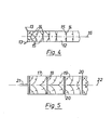
- Figure 4 is a diagram illustrating the progression of two detonation fronts along a strip of explosive material when detonated simultaneously from opposed sides of one end of the strip,
- Figure 5 is a diagrammatic plan view of one . embodiment of explosive cutting means according to the present invention,
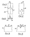
- Figure 6 is a top plan view of another embodiment of explosive cutting means according to the present invention,
- Figure 7 is a side view of the cutting means of Figure 6,
- Figure 8 is an underneath plan view.of the cutting means of Figure 6, and
- Figures 9 and 10 are sections on the lines A and B respectively of Figures 6 and 7.
- Figure 11 is a top plan view of another embodiment of explosive cutting means according to the present. invention,
- Figure 12 is an underneath plan view of the means of Figure 11, and
- Figure 13 is a section through the cutting means of Figure 11.
- Figure 14 is a diagrammatic end elevation of a further embodiment of cutting means according to the invention, and
- Figure 15 is a diagrammatic end elevatlon illustrating a modification of the embodiment of Figure 14.
- Referring to Figure 1 of the drawings it will be seen that if a narrow strip of explosive 1 in contact with a
surface 2 of ametal plate 3 is detonated by means of a detonator 4 shock waves will be produced in themetal plate 3 at each point along the strip of explosive 1 and that these shock waves will emanate from the point of explosive attack as expanding compression waves 5 (shown in full line) and will be reflected back from.theopposite surface 6 of theplate 3 as expanding phase-inverted tension waves 7 (shown in broken line). - Referring now to Figure 2, in which like parts have been given like reference numerals, it will be seen that when two narrow strips of explosive 1 in contact with the
surface 2 of themetal plate 3 are detonated thecompression waves 5 and tension waves 7 so produced coincide and produce along a line extending through the metal plate substantially midway between the two strips of explosive a region of summated maximum pressure which travels from thesurface 2 to thesurface 6 as indicated by thearrow 8 and a region of summated maximum tension which is reflected back from thesurface 6 to thesurface 2 as indicated by the arrow 9. Thus each point along the said line will be subjected to the destructive effects of summated pressure, relaxation and summated tension which, if the explosive charges are sufficient, will induce fracture of themetal plate 3 along said line from thesurface 6 to thesurface 2. - The same effect can be obtained as shown in Figure 3A using a single strip of explosive la in contact with the
surface 2 of ametal plate 3 and detonated simultaneously from both ends by means ofdetonators 4a to produce fracture of themetal plate 3 from thesurface 6 thereof as indicated at 10 in Figure 3B. However, when such a single strip of explosive la is used a second phenomenon occurs in that a narrow cut 11 extending transverse to the strip of explosive la will be produced in thesurface 2 of themetal plate 3 where the two detonation fronts collide. If the explosive la is properly chosen then afracture 10 and a cut 11 can be induced in themetal plate 3 which will combine to sever themetal plate 3. - A strip of explosive la as illustrated in Figure 3 will, of course, only produce a
fracture 10 and a cut 11 of a length substantially equal to the width of the strip of explosive. Clearly it would be advantageous if explosive cutting means could be produced which was in strip form and which could be detonated from opposite lateral side margins thereof. Such a strip-like cutting means could be of any required length and could be laid along a required line of cut to sever the metal plate along the required line of cut. As will be seen from Figure 4, if a strip of explosive 12 is detonated simultaneously from opposite sides of one end thereof by means of detonators 13 the two detonation fronts indicated bylines strip 12 but as detonation proceeds along the length of the strip of explosive 12 the tendency will be for the direction of progression of the detonation fronts to become progressively less inwards and progressively more longitudinal until it is wholly longitudinal. This tendency can be overcome by suitable design of the explosive cutting means. - In the embodiment of the present invention illustrated in Figure 5, explosive cutting means is provided which comprises a
flat strip 17 of explosive material havingdelay elements 18 of non-explosive material e.g., of metal or plastics,or air or gas filling a space incorporated therein. Thedelay elements 18 divide thestrip 17 intoareas 19 which are completely separated from one another except at the ends of theelements 18 where they are connected bybridge portions 20. Asingle detonator 21 is provided at one end of thestrip 17 for detonating the explosive material. It will thus be seen that as detonation proceeds along the length of thestrip 17 it will be periodically interrupted by thedelay elements 18 and begun afresh from the lateral side margins of the strip by virtue of thebridge portions 20, so ensuring the propagation of two detonation fronts each of which progresses both inwardly towards the intended line ofcut 22 and longitudinally of thestrip 17. - In the embodiment of Figures 6 to 10 the explosive cutting means of the present invention comprises a
flat carrier strip 23 of non-explosive material, e.g., a suitable flexible plastics material, havingrecesses 24 in a lower surface thereof which extend across the full width of thestrip 23 and which containexplosive material 25. Alongitudinally extending channel 26 is provided centrally of the upper surface of thestrip 23 and is connected to opposite sides of each of therecesses 24 by means oflateral branch channels 27. Thechannels explosive material 25, or a suitable fuse material, so that when the material in thechannel 26 is detonated or ignited from one end of thestrip 23 detonation will proceed by way of thechannels recesses 24 in turn, whereby detonation of the explosive material in each of therecesses 24 . will proceed from the lateral side margins thereof towards the longitudinal centre of thestrip 23. - The embodiment of Figures 11 to 13 is also in unitary strip form and comprises a carrier or
buffer strip 28 of inert, non-explosive, material, e.g., a suitable flexible plastics material, which is completely enclosed inexplosive material 29 constituting a main charge. Theexplosive material 29 is applied as a thin layer over the upper and side surfaces of thestrip 28 and as a much thicker layer over the lower surface of thestrip 28. A longitudinally extendingstrip 30 of initiating explosive material is provided centrally of the upper surface of thestrip 23 for detonating theexplosive material 29. The initiating explosive material of thestrip 30 is so chosen relative to the main chargeexplosive material 29 as to have a significantly higher detonation velocity than the main charge explosive material, so ensuring that longitudinal propagation in the main chargeexplosive material 29 will be slower than the propagation in the initiatingstrip 30 and that thedetonation fronts 31 of the main chargeexplosive material 29 will be directed both inwardly towards the longitudinal axis of the lower surface of thestrip 28 and longitudinally thereof. - For use underwater or in any situation where the ingress of moisture is likely to be a problem, the explosive cutting means, and particularly a unitary strip-form cutting means of the kind shown in Figure 5, Figures 6 to 10 or Figures 11 to 13, can be sheathed in a suitable waterproof or water-resistant material, e.g., a suitable plastics material. The unitary strip-form cutting means of the present invention can be produced in continuous lengths and can be such that it can be cut to size as required. Moreover in contrast to the known linear cutting charges, the unitary strip-form cutting means of the present invention can be relatively flexible so that it can readily be positioned in contact with a curved surface of a target, e.g., the outer surface of a large diameter cylindrical metal pipe.
- As described hereinbefore with reference to Figures 3A and 3B, the advantage of using explosive cutting means of unitary strip form is that a superficial fracture or cut 11 is produced in the upper surface of the target material which tends to direct the
main fracture 10. An alternative to this is to use explosive cutting means comprising two parallel strips of explosive material arranged one on either side of the intended line of cut and to use a third strip of explosive material extending along the intended line of cut and designed specifically to produce a narrow directing cut.in the upper surface of the target material. - Thus, as shown in Figures 14 and 15, two strips of
explosive material 32 may be provided which are arranged on either side of the intended line of cut and athird strip 33 provided which extends along the intended line of cut and which is designed to produce a superficial cut in that surface of thetarget 34 with which it is in contact. In the embodiment shown in Figure 14 thestrip 33 comprises a conventional lead-sheathed linear cutting charge whilst in the embodiment of Figure 15 it comprises ahollow tube 35 having a layer of explosive material 36 on the outer surface thereof. With the explosive material 36 provided on the outer surface of thehollow tube 35 the ends of the tube can be crimped or otherwise sealed so as to exclude water from the tube and so provide an air space which will allow collapse of the wall of the tube. In either of the embodiments of Figures 14 and 15 the detonation velocity of thestrip 33 must not be lower than that of thestrips 32, unless only a short cut is to be made, since if detonation of thestrips 32 proceeds at a significantly greater rate than that of thestrip 33 the efficacy of thestrip 33 will be impaired. - The embodiment of Figure 16 is an improvement on the embodiment of Figures 6 to 10 and like reference numerals have been used to indicate like parts. In the embodiment of Figure 16 the laterally extending
channels 27 have been replaced by substantiallytriangular recesses 2*7a which contain the explosive or fusematerial 25. The base 27b of eachrecess 27a extends the length of the adjacent lateral side edge of its corresponding recess 24 (Figures 7 and 8) so that detonation will be initiated along the whole of the length of each lateral side edge of eachrecess 24 and not just from the centres of said lateral side edges as in the embodiment of Figures 6 to 10. - With the
triangular recesses 27a of the Figure 16 embodiment, the distance between the apex of each triangular recess and the midpoint of the base is shorter than the distance between the apex and the ends of the base with the result that whenexplosive material 25 in arecess 27a is detonated the detonation front tends to be arcuate so that detonation of the explosive material contained in therecesses 24 does not take place substantially simultaneously at all points along each lateral side edge thereof. This tendency can be overcome or mitigated as shown in Figure 17 by providing spacedbarriers 27c which are so arranged that the shortest path between the apex of eachtriangular recess 27a and each point along the base of the triangular recess is substantially the same. Thebarriers 27c may comprise simply apertures in the explosive material filling therecesses 27a or may comprise bodies of inert material, e.g., projecting upwardly from the bottoms of the recesses and formed integrally with thecarrier strip 23. The explosive cutting means of Figure 17 is particularly useful in situations where the explosive cutting means at one or both ends thereof overlaps a target to be cut as it reduces spalling of the target where it is overlapped by said one or both ends of the cutting means. - The fracture capability of charges of the kind described above in relation to Figures 6 to 10 or Figures 16 or 17 can be improved by forming all or part of the
carrier strip 23 from a high density material such as lead, although the fracture tends to be more irregular. - With explosive cutting means of the kind illustrated in Figure 5 the production of a cut along the
line 22, which coincides with the longitudinal axis of the explosive cutting means, depends upon the two detonation fronts progressing at the same velocity. There is, however, a tendency for one detonation front to progress at a faster rate than the other so that the actual line of cut becomes displaced from the intended line of cut towards the slower detonation front by a distance proportional to the amount by which the slower detonation front lags behind the faster detonation front, this tendency becoming the more exaggerated the longer the explosive cutting means. To mitigate this tendency the explosive cutting means of Figure 5 can be provided at intervals along the length thereof with means for arresting the longitudinal propogation of the two detonation fronts and for re-initiating the two detonation fronts simultaneously from the two lateral side margins of the explosive cutting means. - Said arresting and re-initiating means may be as shown in Figure 18 and may comprise a pair of fairly closely spaced
delay elements 18a similar to thedelay elements 18 and, intermediate thedelay elements 18a, a pair of laterally aligned delay e.lements 18b which are spaced from one another by amedial band 17a of explosive material. It will thus be seen that thedelay elements explosive material 17 which includes theband 17a and which will re-initiate the two detonation fronts simultaneously from both lateral margins of the explosive cutting means irrespective of the longitudinal' direction in which the detonation fronts are progressing. - A similar effect to that obtained by the arresting and re-initiating means of Figure 18 can be obtained with the means shown in Figures 19 and 20. The means shown in Figures 19 and 20 comprises an arresting
element 18c which extends over the full width of the explosive cutting means and is adapted to completely arrest longitudinal progression of the two detonation fronts and an H-shapedbridge 17b of explosive material. Thebridge 17b of explosive material is raised on fourlegs 17c of explosive material above theexplosive material 17 and is arranged with thecentre connecting bar 17d thereof bridging the arrestingelement 18c and with aleg 17c on each side of the arrestingelement 18c at each lateral side margin of the explosive cutting means. - Figure 21 shows a further embodiment of explosive cutting means according to the present invention which comprises a strip of
explosive material 40 having attached to each of its longitudinal side edges a narrow strip ofexplosive material 41 chosen so as to have a significantly higher detonation velocity than the main charge strip ofexplosive material 40. Thus when the strips ofexplosive material 41 are detonated from one end thereof the detonation will proceed longitudinally thereof at a faster rate than the detonation of the main charge and will produce in the main charge twodetonation fronts angle 44 between the twofronts explosive materials angle 44. - It will readily be apparent that if it is desired to make a cut in, e.g., a target steel plate, which is curved or angled in the plane of the target plate then special provisions will need to be made since if a linear cutting means such as is described above were to be laid around a curve so that the cutting means itself was curved laterally then the outside of the curve would be longer than the inside of the curve and this would seriously affect the symmetry of progression of the two detonation fronts. Two solutions to this problem are shown in Figures 22 and 23.
- In the embodiment shown in Figure 22, two linear explosive cutting means of the kind shown in Figure 5 are arranged with an end of one abutting a side margin of the other at a required angle and with the interposition therebetween of a
delay element 18d. Assuming that detonation is progressing in the direction longitudinally of the cutting means indicated by the arrows, anexplosive bridge 45 is provided which makes contact with theexplosive material 17 of the two explosive cutting means only at its ends and which will carry detonation over from the first explosive cutting means and re-initiate it medially of the adjacent end of the second explosive cutting means. - The embodiment shown in Figure 23 is a specially produced corner piece which is similar to the embodiment of Figures 6 to 10 but wherein the
recesses 24 in the lower surface thereof are replaced byrecesses 46 which are so arranged and dimensioned that there will be sufficiently less explosive material in therecesses 46 on the outside of the curve as compared with therecesses 46 on the inside of the curve that detonation will proceed symmetrically around the curve. The corner piece of Figure 23 can be used with linear explosive cutting means of any of the kinds described above and may be provided with anexplosive bridge 47 at each end thereof which is similar to thebridge 45 of the Figure 22 embodiment and which will carry detonation over from a first linear cutting means 48 to the corner piece and then from the corner piece to a second linear cutting means 49. - Figures 24 and 25 illustrate a specific example of a linear explosive cutting means according to the present invention which is based on the embodiment of Figure 5. The example of Figures 24 and 25 may be used for cutting, for example, mild steel plate of about 32mm. in thickness. The linear cutting means of Figures 24 and 25 comprises a first strip 50 illustrated in Figure 24 and a second strip 51 illustrated in Figure 25 which are adapted to be superimposed one upon the other in a manner to be described. The first strip 50 is 3mm. in thickness and comprises
bands 52 of RDX-based sheet explosive SX2, each band being 60mm. long and 20mm. wide and the bands being separated by transverse rubber strips 53 which are 6mm. wide and at least 60mm. long. The second strip 51 is also 3mm. in thickness and comprises bands 54 of the same RDX-based ' sheet explosive and of the same size as thebands 52, the bands 54 being partially separated by transverse rubber strips 55 which are 6mm. wide but only 50mm. long so that a continuous band of explosive 56 which is 5mm. wide extends along each of the lateral side margins of the strip 51. - At one or both ends thereof the strip 51 is tapered to a point and has inset therein a generally
triangular rubber insert 57 so as to provide two initiatingstrips 58 which diverge laterally outwards from acentral initiation point 59. The second strip 51 is superimposed upon the first strip 50 so that the bands 54 of explosive are aligned with thebands 52 and the rubber strips 55 are aligned with the rubber strips 53. The rubber strips 55 may be secured, e.g., adhered, to the rubber strips 53 or may be formed integrally therewith. - The purpose of the delay elements in embodiments such as that shown in Figure 5 is to prevent or retard longitudinal propogation of the detonation fronts without interfering with transverse propogation of the two fronts inwardly towards one another. An alternative method of achieving the same result is possible.
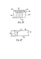
- In connection with Figure 17 it was explained how spaced barriers can be provided in a sheet of explosive material which serve to reduce the apparent velocity of propagation of a detonation front by extending the actual path which at least some increments of the front are caused to follow. Following on from this and turning now to Figure 26, it will readily be appreciated that if a
block 60 of explosive material were to have an array of apertures or other suitable barrier means 61 extending therethrough from the face 62 thereof to theface 63 and such barrier means 61 were to be suitably arranged, then the detonation velocity from theface 64 of theblock 60 to theface 65 or from theface 66 to theface 67 would be retarded by the barrier means 61 whilst the detonation velocity from the face 62 to theface 63 of theblock 60 would be unaffected by the barrier means 61 and would in consequence be higher than as between the other faces. This same principal can be used to good effect to produce an anisotropic explosive sheet or strip material comprising an explosive and a substantially parallel array of filaments or fibres of a suitable barrier material which lie in the plane of the sheet or strip and are so dispersed in the explosive that detonation in one direction in the plane of the sheet or strip will be retarded whilst detonation in the plane of the sheet or strip in a direction perpendicular thereto will be unimpeded. Thus such an anisotropic explosive sheet or strip material will exhibit maximum and minimum detonation velocities in directions perpendicular to one another in the plane of the sheet or strip. Suitable barrier materials for said filaments or fibres include natural or synthetic rubber, suitable plastics materials and metals of high density such as lead. An embodiment of a linear cutting means using such an anisotropic explosive sheet or strip material is illustrated in Figure 27. - Referring to Figure 27 it will be seen that the cutting means illustrated therein comprises a central strip of anisotropic
explosive material 70 havingfilaments 71 of a suitable barrier material so dispersed therein that detonation longitudinally of thestrip 70 will be retarded whilst detonation laterally of thestrip 70 will be unimpeded and therefore of a higher velocity as indicated by thearrows 72 the relative lengths of which are indicative of the relative rate at which detonation proceeds in the direction indicated by each particular arrow. On either side of thecentral strip 70 are strips ofexplosive material 73 which do not incorporate anyfilaments 71 and in which in consequence longitudinal detonation is unimpeded. - The linear cutting means of the present invention may be provided with any suitable means whereby they can be secured to a target to be cut. Thus the linear cutting means may have a suitable contact adhesive, if necessary covered with a suitable release paper, on that surface thereof which is to be in contact with the target. Where said surface includes areas of explosive material and areas of inert material then said adhesive may be applied only to the inert areas so as to avoid any possibility of the adhesive attenuating the effectiveness of the explosive material. Alternatively, if the cutting means is for attachment to ferrous targets, the cutting means may be adapted to attach to ferrous targets magnetically. To this end discrete magnets may be incorporated in the cutting means or, where that surface of the cutting means which is to be applied to the target comprises areas of explosive material and areas of inert material, at least some of said areas of inert material may be magnetic as by forming them from rubber or plastics material having magnetic particles, e.g., of barium ferrite, incorporated therein.
- Whilst in the embodiments of the invention illustrated in the drawings the explosive material used is in solid or plastic form it will be understood that by suitable design of the explosive cutting means powder or liquid explosive materials can be used. Thus, for example, the explosive cutting means could comprise a flat carrier strip similar to the
strip 23 of Figures 6 to 10 but having chambers therein instead of recesses and passages therein instead of channels, the chambers and passages being filled with powder or liquid explosive material.
Claims (30)
Priority Applications (1)
| Application Number | Priority Date | Filing Date | Title |
|---|---|---|---|
| AT81302787T ATE10137T1 (en) | 1980-06-28 | 1981-06-22 | DEVICE FOR EXPLOSION CUTTING. |
Applications Claiming Priority (2)
| Application Number | Priority Date | Filing Date | Title |
|---|---|---|---|
| GB8021273 | 1980-06-28 | ||
| GB8021273 | 1980-06-28 |
Publications (2)
| Publication Number | Publication Date |
|---|---|
| EP0043215A1 true EP0043215A1 (en) | 1982-01-06 |
| EP0043215B1 EP0043215B1 (en) | 1984-10-31 |
Family
ID=10514396
Family Applications (1)
| Application Number | Title | Priority Date | Filing Date |
|---|---|---|---|
| EP81302787A Expired EP0043215B1 (en) | 1980-06-28 | 1981-06-22 | Explosive cutting means |
Country Status (7)
| Country | Link |
|---|---|
| US (1) | US4408535A (en) |
| EP (1) | EP0043215B1 (en) |
| JP (1) | JPS6036920B2 (en) |
| AT (1) | ATE10137T1 (en) |
| DE (1) | DE3166936D1 (en) |
| NO (1) | NO812194L (en) |
| ZA (1) | ZA814223B (en) |
Cited By (10)
| Publication number | Priority date | Publication date | Assignee | Title |
|---|---|---|---|---|
| GB2158565A (en) * | 1984-05-04 | 1985-11-13 | Diehl Gmbh & Co | A cutting charge |
| GB2158923A (en) * | 1984-05-04 | 1985-11-20 | Diehl Gmbh & Co | A cutting charge |
| WO1986007000A1 (en) * | 1985-05-28 | 1986-12-04 | Explosive Developments Limited | Explosive cutting means |
| WO1988002470A3 (en) * | 1986-09-29 | 1988-05-05 | Explosive Dev Ltd | Method for detonating an explosive charge |
| WO1989009376A1 (en) * | 1988-03-24 | 1989-10-05 | The University Of Manchester Institute Of Science | Explosive cutting device with waveguide |
| DE19520136A1 (en) * | 1995-06-01 | 1996-12-05 | Diehl Gmbh & Co | Warhead for combating seas mines |
| EP2434251A1 (en) | 2010-09-22 | 2012-03-28 | Nederlandse Organisatie voor toegepast -natuurwetenschappelijk onderzoek TNO | Explosive cutting |
| RU2618676C1 (en) * | 2016-01-26 | 2017-05-10 | Федеральное государственное унитарное предприятие "Российский Федеральный ядерный центр - Всероссийский научно-исследовательский институт экспериментальной физики" (ФГУП "РФЯЦ-ВНИИЭФ") | Method of metal structures explosive cutting |
| RU2674662C1 (en) * | 2017-11-28 | 2018-12-12 | Федеральное государственное казенное учреждение "12 Центральный научно-исследовательский институт" Министерства обороны Российской Федерации | Device for formation of distributed blast wave |
| CN110095410A (en) * | 2019-05-07 | 2019-08-06 | 西北核技术研究所 | Pattern measurement method, system and ballistic deflection measurement method are injured in target plate perforation |
Families Citing this family (20)
| Publication number | Priority date | Publication date | Assignee | Title |
|---|---|---|---|---|
| US4699066A (en) * | 1985-10-25 | 1987-10-13 | Morton Thiokol Inc. | Linear explosive separation system |
| US6220166B1 (en) * | 1999-08-02 | 2001-04-24 | Sandia Corporation | Apparatus and method for producing fragment-free openings |
| US6530325B2 (en) | 2001-07-11 | 2003-03-11 | Shapiro Brothers, Inc. | Method of scrapping steel structures |
| US6865990B1 (en) | 2003-01-09 | 2005-03-15 | The United States Of America As Represented By The Secretary Of The Navy | Low-cost, no-fragment explosive access tool |
| US7159657B2 (en) * | 2004-03-24 | 2007-01-09 | Schlumberger Technology Corporation | Shaped charge loading tube for perforating gun |
| IL168439A (en) * | 2005-05-05 | 2015-02-26 | Arie Sansolo | Modular breaching apparatus |
| US8408135B2 (en) | 2007-04-26 | 2013-04-02 | Michael L. Greene | Apparatus and method for a low fragment explosive access tool using one piece of explosive sheet in the form of a simple geometric shape, a booster charge of explosive sheet in the form of a disk, a blasting cap, and inert materials |
| US8006621B1 (en) | 2008-02-07 | 2011-08-30 | Cherry Christopher R | Linear explosive breaching apparatus and method |
| US7926423B2 (en) * | 2008-11-14 | 2011-04-19 | The United States Of America As Represented By The Secretary Of The Army | Single-step contact explosive device for breaching reinforced walls and method of use therefor |
| US8887609B1 (en) | 2009-02-27 | 2014-11-18 | Christopher R. Cherry | Explosive system for destruction of overpacked munitions |
| CA2878878A1 (en) * | 2012-06-14 | 2013-12-19 | John Bloomfield | Drilling device and process |
| US9726466B2 (en) * | 2015-02-13 | 2017-08-08 | Dmd Systems, Llc | Fuel/air concussion apparatus |
| WO2018089530A1 (en) | 2016-11-08 | 2018-05-17 | River Front Services, Inc. | Deployable prop |
| US11543224B2 (en) | 2017-08-24 | 2023-01-03 | River Front Services, Inc. | Explosive detonating system and components |
| EP3673227B1 (en) | 2017-08-24 | 2021-06-23 | River Front Services, Inc. | Explosive detonating system and components |
| US10947169B2 (en) * | 2018-06-29 | 2021-03-16 | River Front Services, Inc. | Deployable explosive charge structure |
| RU2730909C1 (en) * | 2019-11-11 | 2020-08-26 | Федеральное государственное казенное учреждение "12 Центральный научно-исследовательский институт" Министерства обороны Российской Федерации | Shock wave generator of explosive type |
| CN113945126B (en) * | 2021-09-23 | 2022-07-08 | 哈尔滨工程大学 | Underwater multi-body cutting and separating device |
| EP4441460A2 (en) | 2021-12-03 | 2024-10-09 | River Front Services, Inc. | Projectile-propelling explosive structure |
| GB2628768A (en) * | 2023-04-03 | 2024-10-09 | Mbda Uk Ltd | Countermeasure |
Citations (10)
| Publication number | Priority date | Publication date | Assignee | Title |
|---|---|---|---|---|
| US2926604A (en) * | 1952-06-30 | 1960-03-01 | Norman A Macleod | Explosion propagating device |
| US2943571A (en) * | 1958-03-18 | 1960-07-05 | Du Pont | Explosive device |
| US3076408A (en) * | 1958-06-11 | 1963-02-05 | Borg Warner | Controlled fracturing of solids by explosives |
| DE1190855B (en) * | 1963-06-20 | 1965-04-08 | Dynamit Nobel Ag | Explosives arrangement for generating a linear detonation front |
| US3374737A (en) * | 1967-02-15 | 1968-03-26 | Earl A. Pike | Detonating tape |
| US3435763A (en) * | 1967-06-20 | 1969-04-01 | Arthur A Lavine | Explosive arrangement for generating a mach stem to affect a line cut |
| US3496868A (en) * | 1967-05-29 | 1970-02-24 | Us Navy | Explosive elements |
| DE1646366A1 (en) * | 1968-01-03 | 1971-07-22 | Ici Ltd | Explosive charges for seismic purposes |
| FR2071315A5 (en) * | 1969-12-24 | 1971-09-17 | France Etat | |
| FR2078815A5 (en) * | 1970-02-20 | 1971-11-05 | Silvia Denis |
Family Cites Families (4)
| Publication number | Priority date | Publication date | Assignee | Title |
|---|---|---|---|---|
| US2774306A (en) * | 1951-11-06 | 1956-12-18 | Norman A Macleod | Means for initiating explosion |
| US3035518A (en) * | 1959-05-25 | 1962-05-22 | Du Pont | Detonation-wave shaper |
| US3280743A (en) * | 1963-05-10 | 1966-10-25 | Hubert G Reuther | Directional control of explosive energy |
| US3404600A (en) * | 1966-09-20 | 1968-10-08 | Air Force Usa | Explosive projector for projectiles |
-
1981
- 1981-01-13 US US06/224,808 patent/US4408535A/en not_active Expired - Fee Related
- 1981-06-22 DE DE8181302787T patent/DE3166936D1/en not_active Expired
- 1981-06-22 AT AT81302787T patent/ATE10137T1/en not_active IP Right Cessation
- 1981-06-22 ZA ZA814223A patent/ZA814223B/en unknown
- 1981-06-22 EP EP81302787A patent/EP0043215B1/en not_active Expired
- 1981-06-25 JP JP56099014A patent/JPS6036920B2/en not_active Expired
- 1981-06-26 NO NO812194A patent/NO812194L/en unknown
Patent Citations (10)
| Publication number | Priority date | Publication date | Assignee | Title |
|---|---|---|---|---|
| US2926604A (en) * | 1952-06-30 | 1960-03-01 | Norman A Macleod | Explosion propagating device |
| US2943571A (en) * | 1958-03-18 | 1960-07-05 | Du Pont | Explosive device |
| US3076408A (en) * | 1958-06-11 | 1963-02-05 | Borg Warner | Controlled fracturing of solids by explosives |
| DE1190855B (en) * | 1963-06-20 | 1965-04-08 | Dynamit Nobel Ag | Explosives arrangement for generating a linear detonation front |
| US3374737A (en) * | 1967-02-15 | 1968-03-26 | Earl A. Pike | Detonating tape |
| US3496868A (en) * | 1967-05-29 | 1970-02-24 | Us Navy | Explosive elements |
| US3435763A (en) * | 1967-06-20 | 1969-04-01 | Arthur A Lavine | Explosive arrangement for generating a mach stem to affect a line cut |
| DE1646366A1 (en) * | 1968-01-03 | 1971-07-22 | Ici Ltd | Explosive charges for seismic purposes |
| FR2071315A5 (en) * | 1969-12-24 | 1971-09-17 | France Etat | |
| FR2078815A5 (en) * | 1970-02-20 | 1971-11-05 | Silvia Denis |
Cited By (14)
| Publication number | Priority date | Publication date | Assignee | Title |
|---|---|---|---|---|
| GB2158565A (en) * | 1984-05-04 | 1985-11-13 | Diehl Gmbh & Co | A cutting charge |
| GB2158923A (en) * | 1984-05-04 | 1985-11-20 | Diehl Gmbh & Co | A cutting charge |
| WO1986007000A1 (en) * | 1985-05-28 | 1986-12-04 | Explosive Developments Limited | Explosive cutting means |
| WO1988002470A3 (en) * | 1986-09-29 | 1988-05-05 | Explosive Dev Ltd | Method for detonating an explosive charge |
| WO1989009376A1 (en) * | 1988-03-24 | 1989-10-05 | The University Of Manchester Institute Of Science | Explosive cutting device with waveguide |
| DE19520136A1 (en) * | 1995-06-01 | 1996-12-05 | Diehl Gmbh & Co | Warhead for combating seas mines |
| DE19520136B4 (en) * | 1995-06-01 | 2005-03-17 | Diehl Stiftung & Co.Kg | Warhead for combating sentinels |
| EP2434251A1 (en) | 2010-09-22 | 2012-03-28 | Nederlandse Organisatie voor toegepast -natuurwetenschappelijk onderzoek TNO | Explosive cutting |
| WO2012039617A1 (en) | 2010-09-22 | 2012-03-29 | Nederlandse Organisatie Voor Toegepast-Natuurwetenschappelijk Onderzoek Tno | Explosive cutting |
| US9163914B2 (en) | 2010-09-22 | 2015-10-20 | Nederlandse Organisatie Voor Toegepast-Natuurwetenschappeluk Onderzoek Tno | Explosive cutting |
| RU2618676C1 (en) * | 2016-01-26 | 2017-05-10 | Федеральное государственное унитарное предприятие "Российский Федеральный ядерный центр - Всероссийский научно-исследовательский институт экспериментальной физики" (ФГУП "РФЯЦ-ВНИИЭФ") | Method of metal structures explosive cutting |
| RU2674662C1 (en) * | 2017-11-28 | 2018-12-12 | Федеральное государственное казенное учреждение "12 Центральный научно-исследовательский институт" Министерства обороны Российской Федерации | Device for formation of distributed blast wave |
| CN110095410A (en) * | 2019-05-07 | 2019-08-06 | 西北核技术研究所 | Pattern measurement method, system and ballistic deflection measurement method are injured in target plate perforation |
| CN110095410B (en) * | 2019-05-07 | 2021-10-08 | 西北核技术研究所 | Target plate perforation damage feature measurement method, system and ballistic deflection measurement method |
Also Published As
| Publication number | Publication date |
|---|---|
| JPS57102800A (en) | 1982-06-25 |
| NO812194L (en) | 1981-12-29 |
| EP0043215B1 (en) | 1984-10-31 |
| ATE10137T1 (en) | 1984-11-15 |
| US4408535A (en) | 1983-10-11 |
| JPS6036920B2 (en) | 1985-08-23 |
| DE3166936D1 (en) | 1984-12-06 |
| ZA814223B (en) | 1983-01-26 |
Similar Documents
| Publication | Publication Date | Title |
|---|---|---|
| US4408535A (en) | Explosive cutting means | |
| CA1316393C (en) | Explosive entry and cutting device and a method of explosive entry and cutting | |
| US2587243A (en) | Cutting apparatus | |
| JP2531944B2 (en) | Explosive drug for straight line cutting | |
| US3374737A (en) | Detonating tape | |
| US3076408A (en) | Controlled fracturing of solids by explosives | |
| US8904934B1 (en) | Segmented flexible linear shaped charge | |
| ATE232576T1 (en) | METHOD FOR DIGING A SIDE | |
| US8459185B1 (en) | Projectile-generating explosive access tool | |
| CO5650185A2 (en) | PERFORATION FLYING | |
| US2980018A (en) | Well perforator shaped charge | |
| US4594946A (en) | Shaped charge chain with booster | |
| JP2514943B2 (en) | Explosive cutting device | |
| CN100570272C (en) | Industrial Explosives Shaped Energy Linear Cutter | |
| RU97109202A (en) | METHOD FOR EXPLOSIVE CUTTING OF SOLID MATERIALS AND DEVICE FOR ITS IMPLEMENTATION | |
| RU2119398C1 (en) | Method for explosion cutting of hard materials and apparatus for performing the same | |
| RU2105946C1 (en) | Method of construction cutting and blast-wave generator | |
| US4699066A (en) | Linear explosive separation system | |
| US9163914B2 (en) | Explosive cutting | |
| RU2104465C1 (en) | Shaped charge | |
| RU2117139C1 (en) | Charging module of tubular shaped-charge perforator | |
| RU2144172C1 (en) | Linear charge | |
| RU2013166C1 (en) | Method of cutting metal structures by extended charges of explosives | |
| RU8113U1 (en) | DEVICE FOR EXPLOSIVE SEPARATION OF EXTENDED METAL STRUCTURES | |
| RU2138759C1 (en) | Blasting cartridge-detonator |
Legal Events
| Date | Code | Title | Description |
|---|---|---|---|
| PUAI | Public reference made under article 153(3) epc to a published international application that has entered the european phase |
Free format text: ORIGINAL CODE: 0009012 |
|
| AK | Designated contracting states |
Designated state(s): AT BE CH DE FR GB IT LU NL SE |
|
| 17P | Request for examination filed |
Effective date: 19820705 |
|
| ITF | It: translation for a ep patent filed | ||
| GRAA | (expected) grant |
Free format text: ORIGINAL CODE: 0009210 |
|
| AK | Designated contracting states |
Designated state(s): AT BE CH DE FR GB IT LI LU NL SE |
|
| REF | Corresponds to: |
Ref document number: 10137 Country of ref document: AT Date of ref document: 19841115 Kind code of ref document: T |
|
| REF | Corresponds to: |
Ref document number: 3166936 Country of ref document: DE Date of ref document: 19841206 |
|
| ET | Fr: translation filed | ||
| PG25 | Lapsed in a contracting state [announced via postgrant information from national office to epo] |
Ref country code: LU Free format text: LAPSE BECAUSE OF NON-PAYMENT OF DUE FEES Effective date: 19850630 |
|
| PLBE | No opposition filed within time limit |
Free format text: ORIGINAL CODE: 0009261 |
|
| STAA | Information on the status of an ep patent application or granted ep patent |
Free format text: STATUS: NO OPPOSITION FILED WITHIN TIME LIMIT |
|
| 26N | No opposition filed | ||
| PGFP | Annual fee paid to national office [announced via postgrant information from national office to epo] |
Ref country code: AT Payment date: 19860613 Year of fee payment: 6 |
|
| PGFP | Annual fee paid to national office [announced via postgrant information from national office to epo] |
Ref country code: NL Payment date: 19860630 Year of fee payment: 6 |
|
| PG25 | Lapsed in a contracting state [announced via postgrant information from national office to epo] |
Ref country code: AT Effective date: 19870622 |
|
| PG25 | Lapsed in a contracting state [announced via postgrant information from national office to epo] |
Ref country code: SE Effective date: 19870623 |
|
| PG25 | Lapsed in a contracting state [announced via postgrant information from national office to epo] |
Ref country code: LI Effective date: 19870630 Ref country code: CH Effective date: 19870630 |
|
| BERE | Be: lapsed |
Owner name: ALFLEX LTD Effective date: 19870630 |
|
| PG25 | Lapsed in a contracting state [announced via postgrant information from national office to epo] |
Ref country code: NL Effective date: 19880101 |
|
| NLV4 | Nl: lapsed or anulled due to non-payment of the annual fee | ||
| PG25 | Lapsed in a contracting state [announced via postgrant information from national office to epo] |
Ref country code: FR Free format text: LAPSE BECAUSE OF NON-PAYMENT OF DUE FEES Effective date: 19880226 |
|
| REG | Reference to a national code |
Ref country code: CH Ref legal event code: PL |
|
| PG25 | Lapsed in a contracting state [announced via postgrant information from national office to epo] |
Ref country code: DE Effective date: 19880301 |
|
| GBPC | Gb: european patent ceased through non-payment of renewal fee | ||
| REG | Reference to a national code |
Ref country code: FR Ref legal event code: ST |
|
| PG25 | Lapsed in a contracting state [announced via postgrant information from national office to epo] |
Ref country code: GB Effective date: 19881118 |
|
| PG25 | Lapsed in a contracting state [announced via postgrant information from national office to epo] |
Ref country code: BE Effective date: 19890630 |
|
| EUG | Se: european patent has lapsed |
Ref document number: 81302787.7 Effective date: 19880712 |