EP0042364B1 - Method and apparatus for adjusting the idling speed rate of an internal combustion otto cycle engine - Google Patents
Method and apparatus for adjusting the idling speed rate of an internal combustion otto cycle engine Download PDFInfo
- Publication number
- EP0042364B1 EP0042364B1 EP81830094A EP81830094A EP0042364B1 EP 0042364 B1 EP0042364 B1 EP 0042364B1 EP 81830094 A EP81830094 A EP 81830094A EP 81830094 A EP81830094 A EP 81830094A EP 0042364 B1 EP0042364 B1 EP 0042364B1
- Authority
- EP
- European Patent Office
- Prior art keywords
- rpm
- threshold
- circuit
- electric motor
- engine
- Prior art date
- Legal status (The legal status is an assumption and is not a legal conclusion. Google has not performed a legal analysis and makes no representation as to the accuracy of the status listed.)
- Expired
Links
- 238000000034 method Methods 0.000 title claims description 11
- 238000002485 combustion reaction Methods 0.000 title claims description 5
- 239000000203 mixture Substances 0.000 claims description 16
- 230000005540 biological transmission Effects 0.000 claims description 15
- 238000012937 correction Methods 0.000 claims description 14
- 230000008569 process Effects 0.000 claims description 10
- 230000033001 locomotion Effects 0.000 claims description 5
- 238000012544 monitoring process Methods 0.000 claims description 5
- 230000000903 blocking effect Effects 0.000 claims description 4
- 230000010355 oscillation Effects 0.000 claims description 4
- 239000000446 fuel Substances 0.000 claims description 2
- 230000001419 dependent effect Effects 0.000 claims 1
- 239000003381 stabilizer Substances 0.000 claims 1
- 230000007257 malfunction Effects 0.000 description 6
- 230000009471 action Effects 0.000 description 5
- 230000002401 inhibitory effect Effects 0.000 description 5
- 230000009467 reduction Effects 0.000 description 5
- 230000001133 acceleration Effects 0.000 description 4
- 230000007423 decrease Effects 0.000 description 4
- 230000000694 effects Effects 0.000 description 4
- 230000008878 coupling Effects 0.000 description 3
- 238000010168 coupling process Methods 0.000 description 3
- 238000005859 coupling reaction Methods 0.000 description 3
- 238000010586 diagram Methods 0.000 description 3
- 239000003054 catalyst Substances 0.000 description 2
- 239000003638 chemical reducing agent Substances 0.000 description 2
- 230000008859 change Effects 0.000 description 1
- 230000009194 climbing Effects 0.000 description 1
- 230000001186 cumulative effect Effects 0.000 description 1
- 229940075591 dalay Drugs 0.000 description 1
- 230000003247 decreasing effect Effects 0.000 description 1
- 238000001914 filtration Methods 0.000 description 1
- 238000002347 injection Methods 0.000 description 1
- 239000007924 injection Substances 0.000 description 1
- 230000007935 neutral effect Effects 0.000 description 1
- 230000003252 repetitive effect Effects 0.000 description 1
- 230000001932 seasonal effect Effects 0.000 description 1
- 230000000087 stabilizing effect Effects 0.000 description 1
- 238000011144 upstream manufacturing Methods 0.000 description 1
Images


Classifications
-
- F—MECHANICAL ENGINEERING; LIGHTING; HEATING; WEAPONS; BLASTING
- F02—COMBUSTION ENGINES; HOT-GAS OR COMBUSTION-PRODUCT ENGINE PLANTS
- F02D—CONTROLLING COMBUSTION ENGINES
- F02D41/00—Electrical control of supply of combustible mixture or its constituents
- F02D41/02—Circuit arrangements for generating control signals
- F02D41/04—Introducing corrections for particular operating conditions
- F02D41/08—Introducing corrections for particular operating conditions for idling
-
- F—MECHANICAL ENGINEERING; LIGHTING; HEATING; WEAPONS; BLASTING
- F02—COMBUSTION ENGINES; HOT-GAS OR COMBUSTION-PRODUCT ENGINE PLANTS
- F02D—CONTROLLING COMBUSTION ENGINES
- F02D31/00—Use of speed-sensing governors to control combustion engines, not otherwise provided for
- F02D31/001—Electric control of rotation speed
- F02D31/002—Electric control of rotation speed controlling air supply
- F02D31/003—Electric control of rotation speed controlling air supply for idle speed control
-
- F—MECHANICAL ENGINEERING; LIGHTING; HEATING; WEAPONS; BLASTING
- F02—COMBUSTION ENGINES; HOT-GAS OR COMBUSTION-PRODUCT ENGINE PLANTS
- F02M—SUPPLYING COMBUSTION ENGINES IN GENERAL WITH COMBUSTIBLE MIXTURES OR CONSTITUENTS THEREOF
- F02M3/00—Idling devices for carburettors
- F02M3/06—Increasing idling speed
- F02M3/07—Increasing idling speed by positioning the throttle flap stop, or by changing the fuel flow cross-sectional area, by electrical, electromechanical or electropneumatic means, according to engine speed
-
- G—PHYSICS
- G01—MEASURING; TESTING
- G01P—MEASURING LINEAR OR ANGULAR SPEED, ACCELERATION, DECELERATION, OR SHOCK; INDICATING PRESENCE, ABSENCE, OR DIRECTION, OF MOVEMENT
- G01P1/00—Details of instruments
- G01P1/07—Indicating devices, e.g. for remote indication
- G01P1/08—Arrangements of scales, pointers, lamps or acoustic indicators, e.g. in automobile speedometers
- G01P1/10—Arrangements of scales, pointers, lamps or acoustic indicators, e.g. in automobile speedometers for indicating predetermined speeds
- G01P1/103—Arrangements of scales, pointers, lamps or acoustic indicators, e.g. in automobile speedometers for indicating predetermined speeds by comparing the value of the measured signal with one or several reference values
-
- F—MECHANICAL ENGINEERING; LIGHTING; HEATING; WEAPONS; BLASTING
- F02—COMBUSTION ENGINES; HOT-GAS OR COMBUSTION-PRODUCT ENGINE PLANTS
- F02B—INTERNAL-COMBUSTION PISTON ENGINES; COMBUSTION ENGINES IN GENERAL
- F02B1/00—Engines characterised by fuel-air mixture compression
- F02B1/02—Engines characterised by fuel-air mixture compression with positive ignition
- F02B1/04—Engines characterised by fuel-air mixture compression with positive ignition with fuel-air mixture admission into cylinder
Definitions
- the present invention relates to an electronic device for adjusting the idling speed rate (number of revolutions per minute) setting of internal combustion Otto cycle engines.
- the device object of the present invention though certainly general in use, has been specially studied to comply with the new anti- pollution laws for the State of California (U.S.A.). According to these laws the engine idling speed rate setting device must not be touched for 80.000 kilometers.
- This device can indifferently operate on the air or on the mixture, when applied to systems with mixture strength correction based on an exhaust gas sensor (feedback systems).
- the feedback sensor automatically corrects the mixture strength, so that it becomes rich or weak depending on the quantity of air added or subtracted by the device in order to maintain the speed rate at a specified level.
- the device to act on a component varying the air/fuel mixture introduced during the idle stage as in the case which will be described later, where the idle speed rate setting screw acts on a carburettor system.
- the object of the present invention is to provide a device of general use on systems with idling speed rate setting via idle speed rate setting screw or mixture by-pass or on systems which by-pass the inducted air, which are very accurate and with full reliability.
- the present invention comprises a device carrying out the above mentioned process including:
- the automatic adjustment system of the engine idling speed rate comprises:
- this device may be the speed rate adjusting screw itself duly modified for coupling to the electric motor.
- the electric motor and the engine speed variation device may be coupled rigidly or flexibly (e.g. Bowden).
- the coupling In this second case, permitting the location of the electric motor away from the most advantageous adjusting point, the coupling must be particularly accurate to avoid any dangerous torsional effect.
- Another possible engine speed rate variation device for the injection system consists of an air by-pass valve with flow section variable by means of a screw.
- the electric motor/screw coupling may be rigid or flexible.
- An electronic control unit which will be described later, processes the signal coming from the spark coil and generates a tachometer signal, indicating the instantaneous engine revolution number per minute which is the system feedback.
- the control is of "window" type, i.e. the adjustment system does not act as long as the speed rate remains within the window or it takes a corrective action by increasing or decreasing the speed rate as required whenever the RPM is not in the window.
- the electric motor increases step-by-step the engine speed rate.
- the system action is sufficiently slow to avoid any oscillations; the correction time, e.g. in the tested prototypes, is of about a step per second (every step corresponds to an average engine speed variation of 20 to 30 RPM).
- the step-by-step system moves on of about 30 RPM to the position B, C up to F; being F positioned within the window, the system stops till the engine speed rate shifts again out of the window.
- Vs MIN The first threshold, Vs MIN, has been introduced to prevent the system from operating if the RPM is very low; particularly in absence of this inhibiting function the mere actuation (energising) of the ignition lock switch, without actually starting the engine, would already preset the control for revving up to the maximum rate possible.
- Thresholds Vs1 and Vs2 limit the adjustment window and determine the normal operation of the system, as shown in Figure 1.
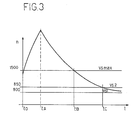
- the threshold Vs MAX has been introduced to inhibit the system operation above a certain engine speed rate, surely corresponding to engine under load (in the present case about 1500 RPM). The need of such a threshold may be explained referring to Figure 3.
- such time may be of 5 or 6 seconds, so that the corrective action would last for such a time, with a consequent too low engine speed rate in the successive idle speed mode.
- the electronic module controlling the system is provided with delay control time at about 2 seconds after the instant at which passage below the Vs MAX threshold occurs and during which time the adjustment continues to be inhibited.
- a delay circuit controlled by the throttle position which operates as follows: as soon as the throttle moves from the closure position, the idle speed control system is inhibited, but it does not operate instantaneously when the throttle is closed, but only after a delay of about 2 seconds.
- the above said timing control avoids a cumulative speed reduction.
- the electronic module takes the moving vehicle signal input; this signal is only a switch activated by the odometer rotor and is usually part of the U.S. version vehicle instrumentation as it is used for the catalyst replacement interval warning system.
- This signal duly processed, supplies a further inhibiting condition of the idle speed rate control system, corresponding to a vehicle speed of about 1 m/sec.
- transmission selector lever When transmission selector lever is in these positions, the contact is closed to earth, the signal reaches the electronic control unit and pre-sets the window to its nominal value, this being applicable to the basic version with manual transmission.
- the battery voltage is applied, through diode 1 for protection against the polarity reversals, to block 2, which provides stabilized voltage supply VO to the integrated circuits and the thresholds.
- the non-stabilized voltage output from block 2 upstream of the stabilizing section reaches block 3 which, through the four transistors TR1, TR2, TR3, TR4, controls the electric motor (indieated as M), previously mentioned, and establishes the rotation of its drive shaft in either directions.
- transistors TR1 and TR4 are conducting, the electric motor M turns in one direction, while the conduction of transistors TR2 and TR3 causes rotation in the opposite direction.
- a resistor R5 is connected between the emitters of transistors TR2 and TR4 and the earth and such emitters are connected to block 4 limiting the current for motor M.
- resistor R5 which is directly proportional to the current flowing through the four transistors TR1, TR2, TR3, TR4, is applied to block 4, and controls the block, which will be described later, which controls the above mentioned four transistor set, reducing the extent of monitoring if the voltage drop at R5 should exceed a given value.
- Block 4 has a double function: if, for any reason, transistor pair TR 1 and TR2 (or TR3 and TR4) is conducting, what could cause a short circuit, block 4 would limit the current value to a non-dangerous level; furthermore, as the electric motor is controlled by pulses, the current must be limited at a fixed value, otherwise the electric motor could operate with different steps, varying with the battery voltage, thus influencing the adjustment speed rate.
- the closed-throttle signal fed to block 5 is filtered and formed by block 6 and transmitted to a delay circuit 7 delaying of about 2 seconds the throttle closing signal which, after such a delay, reaches an inhibiting block 8 which "locks" the oscillator 9 when the throttle is opened.
- the signal of motor vehicle in movement (drive contact from block 10) is filtered and converted from frequency into voltage by block 11 whose output reaches a threshold circuit 12, whose output reaches block 8, constituting a further inhibiting signal for oscillator 9, so that, if the vehicle road speed exceeds a determined speed (about 1 m/sec.), the oscillator will lock.
- the oscillator circuit 9 may be "locked" by the signals Vs MIN and Vs MAX, coming respectively from comparators 13 and 14 (described later); the first comparator 13 avoids the adjustment system to be activated when the engine speed is too low or the engine is inoperative, the second comparator 14 avoids the malfunction already described illustrating Figure 3.
- the oscillator circuit 9 generates frequency pulses of about 1 Hz controlling the step-by-step electric motor operation. This control may be prevented when any blocking signal reaches circuit 8.
- At oscillator circuit 9 arrives the signal coming from a continuous running block 15 when to it are transmitted logic signals of a convenient level coming from a derivator and threshold circuit, which will be described later.
- the oscillator circuit 9 is connected to circuit 16 selecting the control signals for motor clockwise or anticlockwise rotation.
- the selected control signals are supplied to a monitoring circuit 17 of the four transistors TR1, TR2, TR3, TR4.
- the signal from the ignition coil arrives at a divider and filter circuit 18, whose output is fed to a trigger circuit 19, generating a rectangular pulse with the same frequency of the signal from the coil.
- Circuit 19 is connected to a monostable circuit 20 whose output filtered by circuit 21 constitutes the voltage signal Vn directly proportional to the engine RPM.
- This signal Vn is fed to the derivative circuit with threshold 22 processing the Vn signal and generates two logic signals if Vn increases or decreases at a rate exceeding the prefixed threshold; when this occurs the electric motor runs continuously and not step-by-step.
- Circuit 22 actually determines a rapid correction in the presence of a sudden variation of the speed rate, which could occur when the air cooler is switched on or off or when shifting the gear selector lever from N to D in motor vehicles with automatic transmission.
- Circuit 22 supplies two logic signals "a” and "b” to circuit 15 connected to oscillator 9 which, in this case, as already said, will cause the motor to run steplessly.
- Circuit 23 consisting of an adjustable potentiometer associated with a resistive distribution network, allows fixing the tachometer thresholds at the desired value.
- Vs MIN and Vs MAX may also be less accurate and therefore can be obtained after a convenient choice of the distribution network.
- This value is correct for motor vehicles with manual transmission.
- Circuit 24 is monitored by the contact on gearshift lever 25 (for automatics) after filtering and forming (circuit 26) of the signal supplied by the contact; it has also been included a delay circuit 27 avoiding undesired corrections during abrupt shifts from N to D and vice versa.
- the cable transmitting the alternate current signal is directly connected to earth.
- Blocks 28, 29, 30, 13 are four comparators for the definition of the four tachometric thresholds utilized for the system control.
- Circuit 28 representing the maximum threshold (Vs MAX) is connected to the delay circuit 14 that memorises the threshold for about 2 seconds after the downstepping takes place, as already explained.
Landscapes
- Engineering & Computer Science (AREA)
- Chemical & Material Sciences (AREA)
- Combustion & Propulsion (AREA)
- Mechanical Engineering (AREA)
- General Engineering & Computer Science (AREA)
- Physics & Mathematics (AREA)
- General Physics & Mathematics (AREA)
- Electrical Control Of Air Or Fuel Supplied To Internal-Combustion Engine (AREA)
Description
- The present invention relates to an electronic device for adjusting the idling speed rate (number of revolutions per minute) setting of internal combustion Otto cycle engines.
- The device object of the present invention, though certainly general in use, has been specially studied to comply with the new anti- pollution laws for the State of California (U.S.A.). According to these laws the engine idling speed rate setting device must not be touched for 80.000 kilometers.
- it is clear that with a setting adjusted in the factory and then sealed for 80.000 kilometers it is not possible to maintain the idling speed rate within a range acceptable for such a distance (break-in period, seasonal change thermal differences, etc.).
- It is therefore necessary to utilize electronic devices with the engine revolution number (RPM) as feedback signal.
- This device can indifferently operate on the air or on the mixture, when applied to systems with mixture strength correction based on an exhaust gas sensor (feedback systems). In fact, if the device is of a type acting on the air by-pass, the feedback sensor automatically corrects the mixture strength, so that it becomes rich or weak depending on the quantity of air added or subtracted by the device in order to maintain the speed rate at a specified level.
- Instead, if the system works with open loop on the mixture, it is advisable the device to act on a component varying the air/fuel mixture introduced during the idle stage as in the case which will be described later, where the idle speed rate setting screw acts on a carburettor system.
- An apparatus of this type is described in the US-A-3 667 020 which describes an idling speed control apparatus, wherein a predetermined idling speed and two RPM thresholds are defined (upper and lower limit), wherein the actual RPM is compared with the window between these thresholds and wherein, if the RPM is not in the window, a correction of the RPM takes place to bring the RPM into the window to the predetermined idling value by an actuation device. However, systems of this type are not satisfactory for the above mentioned new laws.
- The object of the present invention is to provide a device of general use on systems with idling speed rate setting via idle speed rate setting screw or mixture by-pass or on systems which by-pass the inducted air, which are very accurate and with full reliability.
- According to the invention it is provided a process for the adjustment of the idling speed rate of internal combustion Otto cycle engines for motor vehicles provided with:
- - means indicating the throttle position;
- - means indicating the motor vehicle is moving;
- - means indicating the engine revolution speed rate;
- - means indicating when the automatic gear selector lever is in position D, 1, 2, R and
- - an electronic control unit
- a. the mixture admitting throttle valve is checked to be shut, the signal indicating the throttle is shut being accepted with a pre-established time dalay;
- b. the motor vehicle is checked to be stationary;
- c. the actual engine RPM is checked to be not lower than the lowest predetermined threshold (first threshold);
- d. the actual engine RPM is checked to be not higher than the highest predetermined threshold (fourth threshold), the signal indicating the revving down of the RPM below the highest (fourth) threshold being accepted with a pre-established time delay.
- Additionally the present invention comprises a device carrying out the above mentioned process including:
- -first sensor means (5) for the throttle position arranged to provide at their output an electrical signal indicative that the throttle is opened;
- - detector means (10) arranged to provide at their output an electrical signal indicative that the motor vehicle is moving;
- - speed sensor means (18) arranged to provide at their output an electrical signal indicative of the revolution speed rate of the engine;
- - second sensor means (25) arranged to pro-
- . vide at their output an electrical signal indicative the automatic gear selector lever is in position D, 1, 2, R;
- - a mechanical device for air or mixture adjustment;
- - a 12 V direct current electric motor actuating said mechanical device for air or mixture adjustment;
- -an electronic control unit receiving at its input: the electrical signals from the first sensor means (5), detector means (10), speed sensor means (18), second sensor means (25), and providing as output the order for the electric motor to rotate in the direction required by the control system;
- a. first comparator means (28, 29, 30, 13) arranged to compare the signal indicative of the engine rotation speed rate with four RPM thresholds: Vs min,
Vs 1,Vs 2, Vs max, where Vs min<Vs 1 <Vs 2<Vs max; - b. second comparator means (22) arranged to provide at their output an electric signal when the variation of the engine rotation speed rate exceeds a fixed threshold, in order to make the electric motor to move continuously;
- c. blocking means (8) cooperating with an oscillator (9) adapted to lock this oscillator when at its inputs arrive the signals Vs max, Vs min coming from the first comparator means (28, 13), from the first sensor means (5) and from the detector means (10) so as to lock the electric motor;
- d. controlling means (15) adapted to supply the signals coming from the second comparator means (22) for the stepless electric motor rotation;
- e. inverting means (16) for the inversion of the electric motor rotation according to the position of the actual RPM with respect to
Vs 1 andVs 2. - The invention will be further understood from the following description given by way of nonlimiting example with reference to the accompanying drawings in which:
- Figure 1 represents, by plotting the RPM rates as abscissas and the steps of the step-by-step electric motor (which will be described later) as ordinates, the system correction made.
- Figure 2 represents, by plotting the RPM rates as abscissas and V as ordinates, the trigger diagram of the setting thresholds.
- Figure 3 represents, by plotting times as abscissas and the RPM rate as ordinates, the variation of the RPM rate when the engine suddenly accelerates/decelerates.
- Figure 4 represents the device block diagram, according to the invention.
- The automatic adjustment system of the engine idling speed rate comprises:
- -an electronic control unit receiving at its input: the discharge signal from the ignition coil; the signal of closed-throttle contact; the signal indicating the motor vehicle is moving; the signal of gear box positioned in
Drive - - A 12 V direct current electric motor with reducer (generally it is sufficient a reducer output speed of about 1 turn/sec.) controlled step-by-step by said control unit and with a sufficiently slow repetitiv to avoid instability.
- ·A mechanical device for air or mixture adjustment able to receive the rotary motion from the electric motor and to vary the internal combustion engine speed rate.
- In case of motor vehicle with carburettor this device may be the speed rate adjusting screw itself duly modified for coupling to the electric motor.
- The electric motor and the engine speed variation device may be coupled rigidly or flexibly (e.g. Bowden).
- In this second case, permitting the location of the electric motor away from the most advantageous adjusting point, the coupling must be particularly accurate to avoid any dangerous torsional effect.
- Another possible engine speed rate variation device for the injection system consists of an air by-pass valve with flow section variable by means of a screw.
- Also in this case the electric motor/screw coupling may be rigid or flexible.
- The system is completed by a certain number of signals often already present in the outfit. These signals are:
- - contact on throttle (indicating that the throttle is closed, i.e. that the accelerator pedal is released);
- - contact indicating the gearshift selector lever is on D, 1, 2, R (automatic transmission vehicles only) already present on standard versions to inhibit starting when shift lever is in any gear-engaged position;
- -contact indicating the motor vehicle is in movement; long since normally provided on U.S. version cars to activate the catalyst replacement interval warning-system (switch activated under the action of the odometer rotor).
- The function of these three contacts will be illustrated in the more detailed description of the system.
- An electronic control unit, which will be described later, processes the signal coming from the spark coil and generates a tachometer signal, indicating the instantaneous engine revolution number per minute which is the system feedback.
- The control is of "window" type, i.e. the adjustment system does not act as long as the speed rate remains within the window or it takes a corrective action by increasing or decreasing the speed rate as required whenever the RPM is not in the window.
- In Figure 1 it is schematically represented the way in which the system operates.
- If at a certain instant the engine speed rate corresponds to point A and the conditions exist for the system to be operated in its adjustment mode (the series of conditions which are to be met will be described further on) the electric motor increases step-by-step the engine speed rate.
- The system action is sufficiently slow to avoid any oscillations; the correction time, e.g. in the tested prototypes, is of about a step per second (every step corresponds to an average engine speed variation of 20 to 30 RPM).
- A correction of about 200+300 RPM is therefore operated in about 7=10 seconds (7÷10 steps).
- Still referring to Figure 1 the step-by-step system moves on of about 30 RPM to the position B, C up to F; being F positioned within the window, the system stops till the engine speed rate shifts again out of the window.
- The above stated correction time, though slow, is satisfactory on the prototypes and avoids oscillations which arise very easily. In fact, an idling engine with open loop has slight speed rate flutterings, specially in devices with lambda sensor (a CO sensor) so that a more marked correction could cause oscillations.
- To allow a correct system operation, four tachometric thresholds have been provided, whose stepping sequence diagram is shown in Figure 2.
- The first threshold, Vs MIN, has been introduced to prevent the system from operating if the RPM is very low; particularly in absence of this inhibiting function the mere actuation (energising) of the ignition lock switch, without actually starting the engine, would already preset the control for revving up to the maximum rate possible.
- Thresholds Vs1 and Vs2 limit the adjustment window and determine the normal operation of the system, as shown in Figure 1.
- The threshold Vs MAX has been introduced to inhibit the system operation above a certain engine speed rate, surely corresponding to engine under load (in the present case about 1500 RPM). The need of such a threshold may be explained referring to Figure 3.
- Supposing the engine idles with motor vehicle stationary and that it is accelerated as illustrated in the Figure 3, between instant tO and tA the accelerator pedal is actuated and the engine quickly accelerates, at instant tA the pedal is released; should not threshold Vs MAX avoid the control system to operate, starting from tA, a corrective action, tending to rev down the idle speed would take place, proportional to the time interval in which the engine speed is above
Vs 2. - With engine idling and upon accelerating to 5.000+6.000 RPM, such time may be of 5 or 6 seconds, so that the corrective action would last for such a time, with a consequent too low engine speed rate in the successive idle speed mode.
- This would however not be too serious in case of only one acceleration or deceleration, as the system would restore the speed at the nominal value as soon as the tachometer signal falls below
Vs 1. - In case of repeated accelerations and decelerations the adjustment system keeps reducing, gradually accumulating the effects of revving down to the lowest possible rate.
- In this situation it is very likely that, leaving the engine with closed throttle, the adjustment control would not have sufficient time to make up for the previously activated speed rate reduction and the engine would stall.
- From Figure 3 it can be also noted that the above described malfunction is not avoided simply introducing the threshold Vs MAX which inhibits beyond it the control system operation. In fact this would avoid the malfunction only in the interval tA-tB, while it would be still possible in the interval tB-tC.
- For this reason the electronic module controlling the system is provided with delay control time at about 2 seconds after the instant at which passage below the Vs MAX threshold occurs and during which time the adjustment continues to be inhibited.
- Furthermore, in the electronic module is provided a delay circuit controlled by the throttle position, which operates as follows: as soon as the throttle moves from the closure position, the idle speed control system is inhibited, but it does not operate instantaneously when the throttle is closed, but only after a delay of about 2 seconds.
- This delay avoids the previously described malfunction as a result of slight accelerations in neutral (i.e. such as will not exceed Vs MAX) of a repetitive type.
- In fact in this case the accelerations would be followed by decelerations at closed throttle with dwelling of the RPM above
Vs 2 for about 0,4+0,7 seconds with a consequent order for a speed rate reduction. - The above said timing control avoids a cumulative speed reduction.
- The electronic module takes the moving vehicle signal input; this signal is only a switch activated by the odometer rotor and is usually part of the U.S. version vehicle instrumentation as it is used for the catalyst replacement interval warning system.
- This signal, duly processed, supplies a further inhibiting condition of the idle speed rate control system, corresponding to a vehicle speed of about 1 m/sec.
- . If such inhibiting control were not provided, following malfunction could arise: assuming a gear is engaged and the accelerator pedal is released, the motor vehicle being in motion at low speed and RPM below
Vs 1, the adjustment system would operate by way of increasing the RPM speed rate, but, a gear being engaged, this would lead to a vehicle speed increase which could be moderate if the road is sliqhtlv climbing and the relative speed rate could therefore fail to fall within the control window. - It is possible that in particular situations the system could operate the max. speed rate increase, thus causing an excessive power at the road wheels, certainly not intentional on part of the driver.
- The opposite effect would be on slight downgrades with gear engaged and vehicle moving.
- If the engine speed is out of the window above
threshold Vs 2, the system would reduce the RPM speed rate to the maximum possible limit, so that most likely the engine would falter and stop the moment the clutch were. released.. - In case of a motor vehicle with automatic transmission, there would be a malfunction on downgrades when the engine speed rate is above the window due to the "driving" effect of the torque converter, the automatic control could order a complete speed reduction with the engine turning off the moment the motor vehicle is suddenly braked (spike stops).
- In motor vehicles with automatic transmission it has been verified that it is convenient, even if not essential, to reduce the window value of about 100 RPM when transmission is in D, 1, 2, R in order to avoid a rather notable "motoring over" of the motor vehicle.
- For such a scope it has been utilized the existing contact system, avoiding the starting with the selector lever in any position other than N or P.
- When transmission selector lever is in these positions, the contact is closed to earth, the signal reaches the electronic control unit and pre-sets the window to its nominal value, this being applicable to the basic version with manual transmission.
- When the gearshift lever is in any other position, the contact is no more to earth and this pre-sets a reduction of about 100 RPM to said window value.
- We are now going to describe in detail the electronic circuit according to the present invention, referring to Figure 4.
- The battery voltage is applied, through
diode 1 for protection against the polarity reversals, to block 2, which provides stabilized voltage supply VO to the integrated circuits and the thresholds. - The non-stabilized voltage output from
block 2 upstream of the stabilizing section reachesblock 3 which, through the four transistors TR1, TR2, TR3, TR4, controls the electric motor (indieated as M), previously mentioned, and establishes the rotation of its drive shaft in either directions. - If the transistors TR1 and TR4 are conducting, the electric motor M turns in one direction, while the conduction of transistors TR2 and TR3 causes rotation in the opposite direction.
- If the two transistor couples are cut off, there is obviously no drive from the electric motor.
- A resistor R5 is connected between the emitters of transistors TR2 and TR4 and the earth and such emitters are connected to block 4 limiting the current for motor M.
- The voltage of resistor R5, which is directly proportional to the current flowing through the four transistors TR1, TR2, TR3, TR4, is applied to block 4, and controls the block, which will be described later, which controls the above mentioned four transistor set, reducing the extent of monitoring if the voltage drop at R5 should exceed a given value.
- Block 4 has a double function: if, for any reason,
transistor pair TR 1 and TR2 (or TR3 and TR4) is conducting, what could cause a short circuit, block 4 would limit the current value to a non-dangerous level; furthermore, as the electric motor is controlled by pulses, the current must be limited at a fixed value, otherwise the electric motor could operate with different steps, varying with the battery voltage, thus influencing the adjustment speed rate. - The closed-throttle signal fed to block 5 is filtered and formed by block 6 and transmitted to a
delay circuit 7 delaying of about 2 seconds the throttle closing signal which, after such a delay, reaches an inhibitingblock 8 which "locks" the oscillator 9 when the throttle is opened. - The signal of motor vehicle in movement (drive contact from block 10) is filtered and converted from frequency into voltage by
block 11 whose output reaches athreshold circuit 12, whose output reachesblock 8, constituting a further inhibiting signal for oscillator 9, so that, if the vehicle road speed exceeds a determined speed (about 1 m/sec.), the oscillator will lock. - Furthermore the oscillator circuit 9 may be "locked" by the signals Vs MIN and Vs MAX, coming respectively from comparators 13 and 14 (described later); the first comparator 13 avoids the adjustment system to be activated when the engine speed is too low or the engine is inoperative, the
second comparator 14 avoids the malfunction already described illustrating Figure 3. - The oscillator circuit 9 generates frequency pulses of about 1 Hz controlling the step-by-step electric motor operation. This control may be prevented when any blocking signal reaches
circuit 8. - At oscillator circuit 9 arrives the signal coming from a
continuous running block 15 when to it are transmitted logic signals of a convenient level coming from a derivator and threshold circuit, which will be described later. - The oscillator circuit 9 is connected to
circuit 16 selecting the control signals for motor clockwise or anticlockwise rotation. - The selected control signals are supplied to a
monitoring circuit 17 of the four transistors TR1, TR2, TR3, TR4. - The signal from the ignition coil arrives at a divider and
filter circuit 18, whose output is fed to atrigger circuit 19, generating a rectangular pulse with the same frequency of the signal from the coil. -
Circuit 19 is connected to amonostable circuit 20 whose output filtered bycircuit 21 constitutes the voltage signal Vn directly proportional to the engine RPM. - This signal Vn is fed to the derivative circuit with
threshold 22 processing the Vn signal and generates two logic signals if Vn increases or decreases at a rate exceeding the prefixed threshold; when this occurs the electric motor runs continuously and not step-by-step. -
Circuit 22 actually determines a rapid correction in the presence of a sudden variation of the speed rate, which could occur when the air cooler is switched on or off or when shifting the gear selector lever from N to D in motor vehicles with automatic transmission. -
Circuit 22 supplies two logic signals "a" and "b" tocircuit 15 connected to oscillator 9 which, in this case, as already said, will cause the motor to run steplessly. -
Circuit 23, consisting of an adjustable potentiometer associated with a resistive distribution network, allows fixing the tachometer thresholds at the desired value. - In the described embodiment, it has been preferred only one adjustment instead of four independent adjustments for saving reasons, considering that a greater precision is required for the window adjustment, while Vs MIN and Vs MAX may also be less accurate and therefore can be obtained after a convenient choice of the distribution network.
- In the present case by means of the
potentiometer 23 are fixedonly thresholds Vs 1 andVs 2; all remaining thresholds are consequently fixed at values depending upon the voltage divider, with an accuracy depending solely upon the precision of the voltage divider. - This value is correct for motor vehicles with manual transmission.
- In case of motor vehicles with automatic transmission all thresholds decrease of about 100 RPM and this is obtained through
circuit 24, which, by connecting in parallel topotentiometer circuit 23 the resistor R6, causes the above mentioned decrease. -
Circuit 24 is monitored by the contact on gearshift lever 25 (for automatics) after filtering and forming (circuit 26) of the signal supplied by the contact; it has also been included adelay circuit 27 avoiding undesired corrections during abrupt shifts from N to D and vice versa. - For motor vehicles with manual transmission the cable transmitting the alternate current signal is directly connected to earth.
- In case of motor vehicle with automatic transmission, when gearshift lever is in position N or P, the contact is closed and therefore the thresholds are the same as for the manual transmission; when the lever is in positions D, 1, 2, R the contact is open, and the circuit involved operates the above mentioned decrease.
-
Blocks - Circuit 28, representing the maximum threshold (Vs MAX) is connected to the
delay circuit 14 that memorises the threshold for about 2 seconds after the downstepping takes place, as already explained.
and of the type in which two RPM thresholds (second and third threshold) are defined, wherein the actual RPM is compared with the window between these thresholds and wherein, if the actual RPM is not in the window, a correction of the RPM takes place to bring the actual RPM into the window, acting on the device that varies the amount of the mixture supplied to the engine and characterized in that two other RPM thresholds are predetermined (first and fourth threshold), wherein the first threshold is lower than the second threshold and the fourth threshold is higher than the third threshold, and in that the above mentioned correction of the actual RPM takes place only if:
characterized in that it further includes:
Claims (8)
and of the type in which two RPM thresholds (second and third threshold) are defined, wherein the actual RPM is compared with the window between these thresholds and wherein, if the actual RPM is not in the window, a correction of the RPM takes place to bring the actual RPM into the window, acting on the device that varies the amount of the mixture supplied to the engine and characterized in that two other RPM thresholds are predetermined (first and fourth threshold), wherein the first threshold is lower than the second threshold and the fourth threshold is higher than the third threshold, and in that the above mentioned correction of the actual RPM takes place only if:
characterized in that it further includes:
Applications Claiming Priority (2)
| Application Number | Priority Date | Filing Date | Title |
|---|---|---|---|
| IT67936/80A IT1130482B (en) | 1980-06-16 | 1980-06-16 | ELECTRIC IDLE SETTING DEVICE FOR IDLE SPEED FOR INTERNAL COMBUSTION ENGINES WITH EIGHT CYCLE |
| IT6793680 | 1980-06-16 |
Publications (3)
| Publication Number | Publication Date |
|---|---|
| EP0042364A2 EP0042364A2 (en) | 1981-12-23 |
| EP0042364A3 EP0042364A3 (en) | 1982-05-19 |
| EP0042364B1 true EP0042364B1 (en) | 1984-10-24 |
Family
ID=11306505
Family Applications (1)
| Application Number | Title | Priority Date | Filing Date |
|---|---|---|---|
| EP81830094A Expired EP0042364B1 (en) | 1980-06-16 | 1981-06-05 | Method and apparatus for adjusting the idling speed rate of an internal combustion otto cycle engine |
Country Status (3)
| Country | Link |
|---|---|
| EP (1) | EP0042364B1 (en) |
| DE (1) | DE3166800D1 (en) |
| IT (1) | IT1130482B (en) |
Families Citing this family (5)
| Publication number | Priority date | Publication date | Assignee | Title |
|---|---|---|---|---|
| KR900006089B1 (en) * | 1982-01-30 | 1990-08-22 | 미쓰비시 지도오샤 고오교오 가부시기가이샤 | Engine speed regulating system |
| JPS5993942A (en) * | 1982-11-19 | 1984-05-30 | Fuji Heavy Ind Ltd | Automatic idling-speed governor |
| US4955341A (en) * | 1989-09-18 | 1990-09-11 | General Motors Corporation | Idle control system for a crankcase scavenged two-stroke engine |
| RU2168647C1 (en) * | 1999-12-14 | 2001-06-10 | Общество с ограниченной ответственностью "Проектно-производственное предприятие Дизельавтоматика" | Method to control speed of rotation of internal combustion engine crankshaft |
| RU2209328C2 (en) * | 2001-05-10 | 2003-07-27 | Северо-Кавказский государственный технический университет | Method of and device for automatic control of heat engine shaft speed |
Family Cites Families (3)
| Publication number | Priority date | Publication date | Assignee | Title |
|---|---|---|---|---|
| JPS4945675B1 (en) * | 1969-07-07 | 1974-12-05 | ||
| CA1127273A (en) * | 1978-10-23 | 1982-07-06 | Edwin D. Des Lauriers | Vehicle engine idle speed governor with unsymmetric correction rates |
| US4365599A (en) * | 1979-05-09 | 1982-12-28 | Nissan Motor Company, Limited | Open and closed loop engine idling speed control method and system for an automotive internal combustion engine |
-
1980
- 1980-06-16 IT IT67936/80A patent/IT1130482B/en active
-
1981
- 1981-06-05 EP EP81830094A patent/EP0042364B1/en not_active Expired
- 1981-06-05 DE DE8181830094T patent/DE3166800D1/en not_active Expired
Also Published As
| Publication number | Publication date |
|---|---|
| DE3166800D1 (en) | 1984-11-29 |
| EP0042364A3 (en) | 1982-05-19 |
| IT8067936A0 (en) | 1980-06-16 |
| EP0042364A2 (en) | 1981-12-23 |
| IT1130482B (en) | 1986-06-11 |
Similar Documents
| Publication | Publication Date | Title |
|---|---|---|
| US6751544B2 (en) | Vehicle engine control device | |
| US4336778A (en) | Safety limiter for engine speed | |
| US4484497A (en) | Fuel cut-off system for an engine coupled to an automatic power transmission with a lockup device | |
| EP0142100B1 (en) | Electronic control system for internal combustion engine with stall preventive feature and method for performing stall preventive engine control | |
| GB1601914A (en) | Method of and apparatus for controlling the supply of fuel to an internal combustion engine | |
| US5048482A (en) | Device for controlling an operating characteristic of an internal combustion engine | |
| US4475504A (en) | Method and apparatus for controlling the idling speed of an internal combustion engine | |
| JPH0315036B2 (en) | ||
| EP0339602A2 (en) | System and method for controlling ignition timing for internal combustion engine | |
| EP0194854B1 (en) | Apparatus for controlling the supply of fuel to an internal combustion engine | |
| SE458351B (en) | DEVICE FOR REDUCING THE TORQUE OF A PRINCIPLE BURN ENGINE WITH CONNECTED STEP EXHAUST | |
| KR950006651B1 (en) | Apparatus and method for controlling an internal combustion engine | |
| US4747379A (en) | Idle speed control device and method | |
| EP0042364A2 (en) | Method and apparatus for adjusting the idling speed rate of an internal combustion Otto cycle engine | |
| GB2386206A (en) | A system for and a method of controlling idle speed of an internal combustion engine | |
| JPS6196153A (en) | Method and apparatus for controlling number of rotations of internal combustion engine | |
| US5385128A (en) | Method and device for limiting vehicle speed | |
| US5016181A (en) | Method and system for an engine ignition timing control | |
| KR100289457B1 (en) | Method for controlling the internal combustion engine during no load at low speed | |
| EP0807751A2 (en) | Idling control apparatus of internal combustion engine | |
| EP0096126B1 (en) | Engine governor with reference position for throttle limiter | |
| US5121725A (en) | System and method for controlling engine idling speed applicable to internal combustion engine | |
| JPS633140B2 (en) | ||
| JPH0231781B2 (en) | ||
| WO1999002360A1 (en) | Method of gear changing in a motor vehicle |
Legal Events
| Date | Code | Title | Description |
|---|---|---|---|
| PUAI | Public reference made under article 153(3) epc to a published international application that has entered the european phase |
Free format text: ORIGINAL CODE: 0009012 |
|
| AK | Designated contracting states |
Designated state(s): DE FR GB SE |
|
| PUAL | Search report despatched |
Free format text: ORIGINAL CODE: 0009013 |
|
| AK | Designated contracting states |
Designated state(s): DE FR GB SE |
|
| 17P | Request for examination filed |
Effective date: 19820921 |
|
| GRAA | (expected) grant |
Free format text: ORIGINAL CODE: 0009210 |
|
| AK | Designated contracting states |
Designated state(s): DE FR GB SE |
|
| REF | Corresponds to: |
Ref document number: 3166800 Country of ref document: DE Date of ref document: 19841129 |
|
| ET | Fr: translation filed | ||
| PLBE | No opposition filed within time limit |
Free format text: ORIGINAL CODE: 0009261 |
|
| STAA | Information on the status of an ep patent application or granted ep patent |
Free format text: STATUS: NO OPPOSITION FILED WITHIN TIME LIMIT |
|
| 26N | No opposition filed | ||
| PGFP | Annual fee paid to national office [announced via postgrant information from national office to epo] |
Ref country code: SE Payment date: 19930506 Year of fee payment: 13 |
|
| PGFP | Annual fee paid to national office [announced via postgrant information from national office to epo] |
Ref country code: FR Payment date: 19930514 Year of fee payment: 13 |
|
| PGFP | Annual fee paid to national office [announced via postgrant information from national office to epo] |
Ref country code: GB Payment date: 19930528 Year of fee payment: 13 |
|
| PGFP | Annual fee paid to national office [announced via postgrant information from national office to epo] |
Ref country code: DE Payment date: 19930826 Year of fee payment: 13 |
|
| PG25 | Lapsed in a contracting state [announced via postgrant information from national office to epo] |
Ref country code: GB Effective date: 19940605 |
|
| PG25 | Lapsed in a contracting state [announced via postgrant information from national office to epo] |
Ref country code: SE Effective date: 19940606 |
|
| EUG | Se: european patent has lapsed |
Ref document number: 81830094.9 Effective date: 19950110 |
|
| GBPC | Gb: european patent ceased through non-payment of renewal fee |
Effective date: 19940605 |
|
| PG25 | Lapsed in a contracting state [announced via postgrant information from national office to epo] |
Ref country code: FR Effective date: 19950228 |
|
| PG25 | Lapsed in a contracting state [announced via postgrant information from national office to epo] |
Ref country code: DE Effective date: 19950301 |
|
| EUG | Se: european patent has lapsed |
Ref document number: 81830094.9 |
|
| REG | Reference to a national code |
Ref country code: FR Ref legal event code: ST |