EP0041802B1 - Scroll type fluid displacement apparatus - Google Patents
Scroll type fluid displacement apparatus Download PDFInfo
- Publication number
- EP0041802B1 EP0041802B1 EP81302384A EP81302384A EP0041802B1 EP 0041802 B1 EP0041802 B1 EP 0041802B1 EP 81302384 A EP81302384 A EP 81302384A EP 81302384 A EP81302384 A EP 81302384A EP 0041802 B1 EP0041802 B1 EP 0041802B1
- Authority
- EP
- European Patent Office
- Prior art keywords
- spiral
- seal element
- sealing means
- fluid
- scroll member
- Prior art date
- Legal status (The legal status is an assumption and is not a legal conclusion. Google has not performed a legal analysis and makes no representation as to the accuracy of the status listed.)
- Expired
Links
Images




Classifications
-
- F—MECHANICAL ENGINEERING; LIGHTING; HEATING; WEAPONS; BLASTING
- F01—MACHINES OR ENGINES IN GENERAL; ENGINE PLANTS IN GENERAL; STEAM ENGINES
- F01C—ROTARY-PISTON OR OSCILLATING-PISTON MACHINES OR ENGINES
- F01C19/00—Sealing arrangements in rotary-piston machines or engines
- F01C19/08—Axially-movable sealings for working fluids
-
- F—MECHANICAL ENGINEERING; LIGHTING; HEATING; WEAPONS; BLASTING
- F01—MACHINES OR ENGINES IN GENERAL; ENGINE PLANTS IN GENERAL; STEAM ENGINES
- F01C—ROTARY-PISTON OR OSCILLATING-PISTON MACHINES OR ENGINES
- F01C1/00—Rotary-piston machines or engines
- F01C1/02—Rotary-piston machines or engines of arcuate-engagement type, i.e. with circular translatory movement of co-operating members, each member having the same number of teeth or tooth-equivalents
- F01C1/0207—Rotary-piston machines or engines of arcuate-engagement type, i.e. with circular translatory movement of co-operating members, each member having the same number of teeth or tooth-equivalents both members having co-operating elements in spiral form
- F01C1/0215—Rotary-piston machines or engines of arcuate-engagement type, i.e. with circular translatory movement of co-operating members, each member having the same number of teeth or tooth-equivalents both members having co-operating elements in spiral form where only one member is moving
Definitions
- This invention relates to a fluid displacement apparatus, and more particularly, to a fluid displacement apparatus of the scroll type.
- U.S. Patent No. 801,182 discloses a device including two scroll members each having a circular end plate and a spiroidal or involute spiral element. These scroll members are maintained angularly and radially offset so that both spiral elements interfit to make a plurality of line contacts between their spiral curved surfaces, thereby to seal off and define at least one pair of fluid pockets.
- the relative orbital motion of the two scroll members shifts the line contact along the spiral curved surfaces and, therefore, the fluid pockets change in volume.
- the volume of the fluid pockets increases or decreases dependent on the direction of the orbiting motion. Therefore, the scroll type apparatus is applicable to compress, expand or pump fluids.
- the scroll type compressor In comparison with conventional compressors of the piston type, the scroll type compressor has certain advantages, such as fewer parts and continuous compression of fluid.
- the sealing of the fluid pockets primarily the sealing of the fluid pockets. Sealing of the fluid pockets must be sufficiently maintained in a scroll type fluid displacement apparatus, because the fluid pockets are defined by the line contacts between the interfitting spiral elements and axial contacts between the axial end surfaces of the spiral elements and the inner surfaces of the end plates.
- the pressure of the high pressure fluid introduced must be increased, and the clearance between radial supporting parts must be made as small as possible.
- costly close tolerances of the working parts is required to minimize this clearance, while an increase of the pressure of the introduced fluid results in increased contact pressure between both scroll members, which increases mechanical loss or may damage them.
- Another method for improving the axial seal of the fluid pockets is to use seal elements which are mounted in the axial end surface of each of the spiral elements, as disclosed in U.S. Patent No. 3,994,635 and French Specification No. 2,305,587.
- the end surface of each spiral element facing the end plate of the other scroll member is provided with a groove formed along the spiral.
- a seal element is placed within each of the grooves.
- An axial force urging means in each groove such as a spring, urges the seal toward the facing end surface of the end plate to thereby effect axial sealing.
- the construction for the axial force urging means for the seal is complex, and it is difficult to obtain the desired uniform sealing force along the length of the seal element.
- the seal element is loosely fitted into the groove formed in the axial end surface of each spiral element, and the pressurized fluid is introduced into the groove from adjacent fluid pockets to urge the seal element towards the facing end plate, as a substitute for mechanical urging means, to thereby effect axial sealing.
- the seal element is subject to localized excessive wear during a portion of the orbital motion of the orbiting scroll member. That is, during the period when the pair of fluid pockets are both connected to the central high pressure space, localized fluid pressure behind the seal element is suddenly enlarged, resulting in excessive sealing force which sometimes induces localized bending of the seal element and excessive sealing force.
- the apparatus should have a simple construction, a simple production method, and low cost.
- a scroll type fluid displacement apparatus including a pair of scroll members each comprising an end plate and a spiral wrap means extending from one surface of said end plate, each spiral wrap means being provided with a groove which is formed in an axial end surface thereof and extends along the spiral curve of the wrap means and the wrap means interfitting at an angular offset with a plurality of line contacts so as to define at least one pair of sealed off fluid pockets, drive means operatively connected to one of said scroll members to cause said one scroll member to undergo orbital motion relative to the other scroll member, means for preventing rotation of said one scroll member, whereby said fluid pockets change volume upon orbital motion of said one scroll member, and seal elements having a spiral configuration corresponding to the configuration of said spiral wrap means and loosely fitted in said groove of respective wrap means characterised in that each seal element comprises sealing means formed of a material which has a high sealing efficiency and a low coefficient of friction, said sealing means having the said spiral configuration and having a contact surface adapted to engage the end plate of
- One embodiment of the invention is a scroll type fluid displacement apparatus which includes a pair of scroll members each comprising an end plate and a spiral wrap means extending from one side of the end plate.
- the spiral wrap means is provided with a groove which is formed in the axial end surface thereof and extends along the spiral curve of the wrap means.
- a seal element is loosely fitted in the groove, and has a reinforcement member for preventing the localized bending thereof.
- the pressurized fluid flows from adjacent fluid pockets which are formed between the interfitting scroll members into the groove to urge the seal element into contact with the opposite end plate, without localized bending.
- the seal element comprises a sliding member and a core member as the reinforcement member.
- the core member is formed of a metal having a high rigidity, such as steel, and the sliding member is formed of a material which has a high sealing efficiency with low friction coefficient, such as polytetrafluoroethylene (PTFE) resin.
- PTFE polytetrafluoroethylene
- the sliding member of the seal element may be disposed within a channel-shaped guide member.
- the axial end surface of the sliding member extends from the opening portion of the guide member. Therefore, sufficient rigidity of the seal element is afforded by the guide member.
- Integral springy protrusions formed on the bottom wall of the guide member urge the sliding member into sealing engagement with the end plate.
- a seal element mounted in the axial end surface of each spiral element is urged towards the end plate of the other spiral element by the pressure differential across the end surface of the spiral element to ensure axial sealing.
- Fixed scroll member 13 includes a circular end plate 131, a wrap or spiral element 132 affixed to or extending from one side surface of circular plate 131, and a plurality of internally threaded bosses 133 axially projecting from the end surface of plate 131 opposite to the side thereof from which spiral element 132 extends.
- the end surface of each boss 132 is seated on the inner surface of end plate portion 121 of cup-shaped casing 12 and is fixed to end plate portion 121 by a bolt 15.
- fixed scroll member 13 is fixedly disposed within cup-shaped casing 12.
- Circular plate 131 of fixed scroll member 13 partitions the inner chamber of cup-shaped casing 12 into discharge chamber 16 and suction chamber 17 by a seal ring 135 disposed between the outer peripheral surface of circular plate 131 and the inner wall of cup-shaped casing 12.
Landscapes
- Engineering & Computer Science (AREA)
- Mechanical Engineering (AREA)
- General Engineering & Computer Science (AREA)
- Rotary Pumps (AREA)
Description
- This invention relates to a fluid displacement apparatus, and more particularly, to a fluid displacement apparatus of the scroll type.
- Scroll type apparatus are well known in the prior art. For example, U.S. Patent No. 801,182 discloses a device including two scroll members each having a circular end plate and a spiroidal or involute spiral element. These scroll members are maintained angularly and radially offset so that both spiral elements interfit to make a plurality of line contacts between their spiral curved surfaces, thereby to seal off and define at least one pair of fluid pockets. The relative orbital motion of the two scroll members shifts the line contact along the spiral curved surfaces and, therefore, the fluid pockets change in volume. The volume of the fluid pockets increases or decreases dependent on the direction of the orbiting motion. Therefore, the scroll type apparatus is applicable to compress, expand or pump fluids.
- In comparison with conventional compressors of the piston type, the scroll type compressor has certain advantages, such as fewer parts and continuous compression of fluid. However, there have been several problems, primarily the sealing of the fluid pockets. Sealing of the fluid pockets must be sufficiently maintained in a scroll type fluid displacement apparatus, because the fluid pockets are defined by the line contacts between the interfitting spiral elements and axial contacts between the axial end surfaces of the spiral elements and the inner surfaces of the end plates.
- One solution to the sealing problem, in particular, that relating to axial sealing, is described in U.S. Patent No. 3,874,827. This patent discloses the concept of non-rotatably supporting the fixed scroll member within the compressor housing in an axially floating condition. A high pressure fluid is introduced behind the fixed scroll member to establish sufficient axial sealing. In this arrangement, since the fixed scroll member is supported in an axially floating condition, the fixed scroll member member may wobble due to the eccentric orbital motion of the orbiting scroll member. Therefore, sealing and resultant fluid compression tends to be imperfectly performed.
- In order to avoid these disadvantages, the pressure of the high pressure fluid introduced must be increased, and the clearance between radial supporting parts must be made as small as possible. However, costly close tolerances of the working parts is required to minimize this clearance, while an increase of the pressure of the introduced fluid results in increased contact pressure between both scroll members, which increases mechanical loss or may damage them.
- Another method for improving the axial seal of the fluid pockets is to use seal elements which are mounted in the axial end surface of each of the spiral elements, as disclosed in U.S. Patent No. 3,994,635 and French Specification No. 2,305,587. In this arrangement, the end surface of each spiral element facing the end plate of the other scroll member is provided with a groove formed along the spiral. A seal element is placed within each of the grooves. An axial force urging means in each groove, such as a spring, urges the seal toward the facing end surface of the end plate to thereby effect axial sealing. In this arrangement, the construction for the axial force urging means for the seal is complex, and it is difficult to obtain the desired uniform sealing force along the length of the seal element.
- In order to avoid these disadvantages, the seal element is loosely fitted into the groove formed in the axial end surface of each spiral element, and the pressurized fluid is introduced into the groove from adjacent fluid pockets to urge the seal element towards the facing end plate, as a substitute for mechanical urging means, to thereby effect axial sealing. However, the seal element is subject to localized excessive wear during a portion of the orbital motion of the orbiting scroll member. That is, during the period when the pair of fluid pockets are both connected to the central high pressure space, localized fluid pressure behind the seal element is suddenly enlarged, resulting in excessive sealing force which sometimes induces localized bending of the seal element and excessive sealing force.
- It is a primary object of this invention to provide an efficient scroll type fluid displacement apparatus wherein the axial sealing of the fluid pockets is ensured and concentrated wear of the seal elements is prevented. The apparatus should have a simple construction, a simple production method, and low cost.
- According to the invention, in its broadest aspect, there is provided a scroll type fluid displacement apparatus including a pair of scroll members each comprising an end plate and a spiral wrap means extending from one surface of said end plate, each spiral wrap means being provided with a groove which is formed in an axial end surface thereof and extends along the spiral curve of the wrap means and the wrap means interfitting at an angular offset with a plurality of line contacts so as to define at least one pair of sealed off fluid pockets, drive means operatively connected to one of said scroll members to cause said one scroll member to undergo orbital motion relative to the other scroll member, means for preventing rotation of said one scroll member, whereby said fluid pockets change volume upon orbital motion of said one scroll member, and seal elements having a spiral configuration corresponding to the configuration of said spiral wrap means and loosely fitted in said groove of respective wrap means characterised in that each seal element comprises sealing means formed of a material which has a high sealing efficiency and a low coefficient of friction, said sealing means having the said spiral configuration and having a contact surface adapted to engage the end plate of the opposite scroll member and reinforcement means formed of a metal and being of substantial rigidity, said reinforcement means having the said spiral configuration and being fixed to the associated sealing means throughout the length thereof to provide rigidity to said seal element so as to prevent said seal element from being subjected to local bending by a locally increased back-up fluid pressure behind said seal member.
- One embodiment of the invention is a scroll type fluid displacement apparatus which includes a pair of scroll members each comprising an end plate and a spiral wrap means extending from one side of the end plate. The spiral wrap means is provided with a groove which is formed in the axial end surface thereof and extends along the spiral curve of the wrap means. A seal element is loosely fitted in the groove, and has a reinforcement member for preventing the localized bending thereof. During operation, the pressurized fluid flows from adjacent fluid pockets which are formed between the interfitting scroll members into the groove to urge the seal element into contact with the opposite end plate, without localized bending.
- Suitably, the seal element comprises a sliding member and a core member as the reinforcement member. The core member is formed of a metal having a high rigidity, such as steel, and the sliding member is formed of a material which has a high sealing efficiency with low friction coefficient, such as polytetrafluoroethylene (PTFE) resin.'Hence, when the fluid pressure behind the seal element is changed, the localized bending of the seal element is prevented by the core member.
- The sliding member of the seal element may be disposed within a channel-shaped guide member. The axial end surface of the sliding member extends from the opening portion of the guide member. Therefore, sufficient rigidity of the seal element is afforded by the guide member. Integral springy protrusions formed on the bottom wall of the guide member urge the sliding member into sealing engagement with the end plate.
- Although a preferred embodiment of the invention is a scroll-type compressor, various scroll-type fluid displacement apparatus other than compressors are also included within the scope of the invention.
- The invention will now be described, by way of example, with reference to the accompanying drawings, in which:-
- Figs. 1a1d are views illustrating the principle of the operation of a scroll type compressor;
- Fig. 2 is a vertical sectional view of a compressor unit in accordance with this invention;
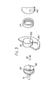
- Fig. 3 is an exploded perspective view of the driving mechanism of the embodiment of Fig. 2;
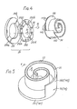
- Fig. 4 is an exploded perspective view of the rotation preventing/thrust bearing mechanism of the embodiment of Fig. 2;
- Fig. 5 is a perspective view of either scroll member of the apparatus according to this invention.
- Fig. 6 is a sectional view taken along
line 6―6 in Fig. 5 illustrating a detail of one embodiment of the invention; - Fig. 7 is a sectional view similar to Fig. 6 of part of another embodiment;
- Fig. 8 is a sectional view similar to Fig. 6 of part of still another embodiment;
- Fig. 9 is a sectional view similar to Fig. 6 of part of still another embodiment;
- Fig. 10 is a sectional view of a seal element according to one embodiment of this invention;
- Fig. 11 is a sectional view similar to Fig. 10 of another embodiment; and
- Fig. 12 is a perspective view of a guide member according to one embodiment of this invention.
- Before the preferred embodiments of this invention will be described, the principle of operation of the scroll type compressor unit will be described with reference to Figs. 1a-1d. The scroll type compressor unit operates by moving sealed off fluid pockets from a low pressure region to a high pressure region.
- Figs. 1 a-1 may be considered to be end views of a compressor unit wherein the end plates are removed and only spiral elements are shown.
- Two
spiral elements 1 and 2 are angularly offset and interfit with one another. As shown in Fig. 1a, the orbiting spiral element 1 and fixedspiral element 2 make four line contacts due to the radial offset of one spiral as shown at four points A-D. A pair offluid pockets 3a and 3b are defined between line contacts D, C and line contacts A, B, as shown by the dotted regions. Thefluid pockets 3a and 3b are defined not only by the walls ofspiral elements 1 and 2, but also by the end plates from which these spiral elements extend. When orbiting spiral element 1 is moved in relation to fixedspiral element 2 so that the center 0' of orbiting spiral element 1 revolves around the center 0 of fixedspiral element 2 with a radius of 0-0' while the rotation of orbiting spiral element 1 is prevented, the pair offluid pockets 3a and 3b shift angularly and radially toward the center of the interfitted spiral elements with the volume of eachfluid pocket 3a and 3b being gradually reduced, as shown in Figs. 1a-1d. Therefore, the fluid in each pocket is compressed. - Now, the pair of
fluid pockets 3a and 3b are connected to one another while passing the stage from Fig. 1c to Fig. 1d, and, as shown in Fig. 1a, bothpockets 3a and 3b merge at thecentral portion 5 and are completely connected to one another to form a single pocket. The volume of the connected single pocket is further reduced by further revolutions of 90° as shown in Figs. 1b, 1c and 1d, and is substantially zero in status of Fig. 1d. During the course of rotation, outer spaces which open in the state shown in Fig. 1b change as shown in Figs. 1c, 1d and 1a to form new sealed off pockets in which fluid is newly enclosed. - Accordingly, if circular end plates are disposed on and sealed to the axial facing ends of
spiral elements 1 and 2, respectively, and if one of the end plates is provided with adischarge port 4 at the center thereof as shown in the figures, fluid is taken into the fluid pockets at the radial outer portions and is discharged from thedischarge port 4 after compression. - In order to compress the fluid, it is important that each fluid pocket be sufficiently sealed.
- In this invention, a seal element mounted in the axial end surface of each spiral element is urged towards the end plate of the other spiral element by the pressure differential across the end surface of the spiral element to ensure axial sealing.
- Referring to Fig. 2, a compressor unit, such as a refrigerant compressor, is shown which includes a
compressor housing 10 comprising afront end plate 11 and a cup-shapedcasing 12 disposed on the end surface of thefront end plate 11. - A fixed
scroll member 13, anorbiting scroll member 14, and driving mechanism and a rotation preventing/thrust bearing mechanism or orbitingscroll member 14 are disposed within an inner chamber of cup-shapedcasing 12 which is formed between inner wall of cup-shapedcasing 12 and end surface offront end plate 11. -
Fixed scroll member 13 includes acircular end plate 131, a wrap orspiral element 132 affixed to or extending from one side surface ofcircular plate 131, and a plurality of internally threadedbosses 133 axially projecting from the end surface ofplate 131 opposite to the side thereof from which spiralelement 132 extends. The end surface of eachboss 132 is seated on the inner surface ofend plate portion 121 of cup-shapedcasing 12 and is fixed toend plate portion 121 by abolt 15. Hence, fixedscroll member 13 is fixedly disposed within cup-shapedcasing 12.Circular plate 131 of fixedscroll member 13 partitions the inner chamber of cup-shapedcasing 12 intodischarge chamber 16 andsuction chamber 17 by aseal ring 135 disposed between the outer peripheral surface ofcircular plate 131 and the inner wall of cup-shapedcasing 12. - Orbiting
scroll member 14 is disposed insuction chamber 17 of thecasing 12 and also comprises acircular end plate 141 and a wrap means orspiral element 142 affixed or extending from one side surface ofcircular plate 141.Spiral element 142 andspiral element 132 of fixedscroll member 13 interfit at an angular offset of 180° and a predetermined radial offset; therefore, a pair of fluid pockets are defined betweenspiral elements scroll member 14 is connected to the driving mechanism and to the rotation preventing/thrust bearing mechanism. These last two mechanisms effect orbital motion at circular radius Ro by rotation ofdrive shaft 18, which is rotatably supported byfront end plate 11, to thereby compress the fluid, as described in connection with Fig. 1. - Referring to Fig. 2 and Fig. 3, the driving mechanism of orbiting
scroll member 14 will be described. Driveshaft 18 is rotatably supported by asleeve portion 111 offront end plate 11, which projects from the front surface offront end plate 11, through abearing 24. Driveshaft 18 has adisk portion 181 at its inner end portion.Disk portion 181 is also rotatably supported byfront end plate 11 through abearing 25 which is disposed within an opening offront end plate 11. - A crank pin or drive
pin 182 axially projects from an end surface ofdisk portion 181 and is radially offset from the center ofdrive shaft 18.Circular end plate 141 of orbitingscroll member 14 is provided with atubular boss 143 axially projecting from an end surface opposite to the side thereof from which spiralelement 142 extends. A discoid or shortaxial bushing 26 is fitted intoboss 143 and is rotatably supported therein by a bearing means, such as aneedle bearing 27.Bushing 26 has abalance weight 261 which is shaped as a portion of a disc or ring and extends radially from bushing 26 along a front surface thereof. Aneccentric hole 262 is formed inbushing 26, radially offset from the center ofbushing 26.Drive pin 182 is fitted into the eccentricallydisposed hole 262 within which abearing 28 may be applied.Bushing 26 is therefore driven by the revolution ofdrive pin 182 and permitted to rotate byneedle bearing 27. - A
pulley 31 is rotatably supported by abearing 32.Bearing 32 is disposed on the outer surface ofsleeve portion 111. An electromagneticannular coil 33 is fixed to the outer surface ofsleeve portion 111 and is received in an annular cavity ofpulley 31. Anarmature plate 34 is elastically supported on the outer end ofdrive shaft 18 which extends fromsleeve portion 111. A magneticclutch comprising pulley 31,magnetic coil 33 andarmature plate 34 is thereby formed. Thus, driveshaft 18 is driven by an external drive power source, for example, a motor of a vehicle, through a rotation force transmitting means, such as the magnetic clutch. - Now, the rotation of orbiting
scroll member 14 is prevented by a rotation preventing/thrust bearing means 29 which is disposed between the inner surface of thehousing 10 andcircular plate 141 of the orbiting scroll member, whereby orbitingscroll member 14 orbits while maintaining its angular orientation relative to the fixed scroll member. - Referring to Fig. 4 and Fig. 1, rotation preventing/thrust bearing means 29 will be described. Rotation preventing/thrust bearing means 29 is disposed to surround
boss 143 and is comprised of a fixedring 291 and a slidingring 292.Fixed ring 291 is secured to an end surface offront end plate 11 bypins 293.Fixed ring 291 is provided with a pair ofkeyways 291 a, 291 b in an axial end surface facing orbitingscroll member 14. Slidingring 292 is disposed in a hollow space between fixedring 291 andcircular plate 141 of orbitingscroll member 14. Slidingring 292 is provided with a pair ofkeys 292a, 292b on the surface facing fixedring 291, which are received inkeyways 291 a, 291 b. Therefore, slidingring 292 is slidable in the radial direction by the guide ofkeys 292a, 292b withinkeyways 291 a, 291 b. Slidingring 292 is also provided with a pair ofkeys 292c, 292d on its opposite surface.Keys 292c, 292d are arranged along a diameter perpendicular to the diameter along whichkeys 292a, 292b are arranged.Circular plate 141 or orbitingscroll member 14 is provided with a pair of keyways (in Fig. 4 only one ofkeyways 141a is shown; the other keyway is disposed diametrically opposite tokeyway 141a) on a surface facing slidingring 292 in which are receivedkeys 292c, 292d. Therefore, orbitingscroll member 14 is slidable in a radial direction by the guide ofkeys 292c, 292d within the keyways ofcircular plate 141. - Accordingly, orbiting
scroll member 14 is slidable in one radial direction with slidingring 292, and is slidable in another radial direction independently. The second direction is perpendicular to the first direction. Therefore, orbitingscroll member 14 is prevented from rotating, but is permitted to move in two radial directions perpendicular to one another. - In addition, sliding
ring 292 is provided with a plurality of pockets or holes 30 which are formed in an axial direction. A bearing means, such asballs 31, each having a diameter which is larger than the thickness of slidingring 292, are retained inpockets 30.Balls 31 contact and roll on the surface of fixedring 291 andcircular plate 141. Therefore, the axial thrust load from orbitingscroll member 14 is supported on fixedring 291 through bearing means 31. - Thus, when orbiting
scroll member 14 is allowed to undergo the orbital motion of radius Ro by the rotation ofdrive shaft 18, fluid or refrigerant gas introduced intosuction chamber 17 from an external fluid circuit throughinlet port 19 oncasing 12, is drawn into the fluid pockets formed between both spiral elements 132,142. As orbitingscroll member 14 orbits, fluid in the fluid pockets is moved to the center of the spiral elements with a consequent reduction of volume thereof. Compressed fluid is discharged intodischarge chamber 16 from the fluid pocket at the center of the spiral elements through ahole 134 which is formed throughcircular plate 131 at a position near to the center ofspiral element 132 and therefrom is discharged through anoutlet port 20 to an external fluid circuit, for example, a cooling circuit. - Referring to Fig. 5, each spiral element 132,142 is provided with a
groove 21 formed in its axial end surface along the spiral curve.Groove 21 extends from the inner end of the spiral element to a position close to the terminal end of the spiral element. - A
seal element 22 is loosely fitted withingroove 21. A hollow space remains between the groove and the seal element adjacent the bottom surface ofgroove 21, as shown in Figs. 6-9. Thus, the hollow space is connected to adjacent fluid pockets which are formed betweeninterfitting scroll members spiral elements seal element 22 and the side walls ofgroove 21. Therefore, during operation the compressed fluid flows from adjacent fluid pockets into the hollow space to urgeseal element 22 into contact with the opposite circular plate so that a seal between the spiral elements and the circular plate is effected. -
Seal element 22 disposed withingroove 21 is provided with a reinforcement member to prevent the localized bending ofseal element 22. Referring to Figs. 6-8, embodiments ofseal element 22 having a core member as the reinforcement member will be described.Seal element 22 comprises a slidingmember 222 which is formed of a material having a high sealing efficiency with low friction coefficient, such as PTFE, having a contact surface adapted to engage the opposite circular plate and acore member 221 which is formed of a metal having a substantial rigidity, such as steel.Core member 221 is inserted near the center of slidingmember 222, as shown in Fig. 6. Therefore, when the high local fluid pressure acts againstseal element 22, localized bending ofseal element 22 is prevented to thereby prevent localized wear of the seal element. - In an alternative embodiment, sliding
member 222 is affixed to the axial end surface ofcore member 221 so that the axial end surface of slidingmember 222 contacts the opposite circular plate, as shown in Fig. 7. According to this construction ofseal element 22, the production of the seal element is very easy and inexpensive, because the seal element is obtained by the following process. At first, the sliding member, such as a plate of PTFE resin is affixed to the surface of a plate of material for the core member. These bonded plates are then cut together in a spiral configuration by a punch or the like, so that the seal element is easily obtained. - In another embodiment, two sliding
members 222a and 222b are affixed to the opposite side surfaces ofcore member 221 so that the axial end surface ofcore member 221 is recessed from the plate contacting surfaces of slidingmembers 222a and 222b, as shown in Fig. 8. According to this construction, the production of the seal element is very easy and inexpensive. First, two concentric tubes of plastic material for the sliding member are bonded to the outer and inner surfaces of a tube of steel for the core member. Then a cylindrical slice is cut from the composite tubular structure to form a ring. The exposed edge of the steel portion is etched to form a recess in the steel between the plastic portions. The ring is cut open so that it can be inserted into thespiral groove 21 in the spiral element. - Figs. 9-12 illustrate other embodiments of the seal element wherein the seal element has a guide member as the reinforcement member. Sliding
member 222 is formed of a material which has a high sealing efficiency with low friction coefficient, such as PTFE resin, and is disposed within a channel-shapedguide member 23. The axial end surface of slidingmember 222 projects from the opening portion ofguide member 23. - Now, sliding
member 222 is formed with stepped portions orshoulders 223 near the axial end surface thereof (Figs. 9, 10), and the edges of the opening of theguide member 23 are inwardly bent at 231 for engagement withshoulders 223 of slidingmember 222, as shown in Fig. 10. Therefore, slidingmember 222 is securely held withinguide member 23 without axial movement. - Fig. 11 shows another embodiment of a seal element holding construction wherein
indentations 224 are formed along both side surfaces ofseal element 22 andinward projections 232 are formed on both side walls ofguide member 23 for engaging theindentations 224. Therefore, slidingmember 222 is securely held withinguide member 23 without axial movement. - According to these constructions, the sliding
member 222 is held withinguide member 23 without axial movement. Therefore, when the fluid pressure acting to seal element partly changes, the localized bending ofseal element 22 is prevented thereby reducing localized wear on slidingmember 222. - Preferably, a plurality of projecting tongues are integrally formed or cut from the bottom portion of
guide member 23, as shown in Fig. 12. The urging force acting to sealelement 22 is in part due to the elasticity oftongues 233 and the fluid back pressure to thereby ensure the axial sealing of the fluid pockets. - Especially at the outer portion of the spiral elements, sufficient sealing force cannot be expected due to a lower pressure differential across the spiral end surface. An axially urging force which does not depend upon the pressure differential is ideal for some applications. In these cases, the width of the groove is made substantially the same as that of the seal element to leave no radial clearance for fluid to enter the space formed between the groove bottom and the seal element.
Claims (18)
Applications Claiming Priority (4)
| Application Number | Priority Date | Filing Date | Title |
|---|---|---|---|
| JP7464380U JPS5792U (en) | 1980-05-31 | 1980-05-31 | |
| JP74643/80U | 1980-05-31 | ||
| JP115455/80U | 1980-08-13 | ||
| JP11545580U JPS5742186U (en) | 1980-08-13 | 1980-08-13 |
Publications (2)
| Publication Number | Publication Date |
|---|---|
| EP0041802A1 EP0041802A1 (en) | 1981-12-16 |
| EP0041802B1 true EP0041802B1 (en) | 1985-03-27 |
Family
ID=26415814
Family Applications (1)
| Application Number | Title | Priority Date | Filing Date |
|---|---|---|---|
| EP81302384A Expired EP0041802B1 (en) | 1980-05-31 | 1981-05-29 | Scroll type fluid displacement apparatus |
Country Status (5)
| Country | Link |
|---|---|
| US (1) | US4453899A (en) |
| EP (1) | EP0041802B1 (en) |
| AU (1) | AU547490B2 (en) |
| CA (1) | CA1221949A (en) |
| DE (1) | DE3169516D1 (en) |
Cited By (1)
| Publication number | Priority date | Publication date | Assignee | Title |
|---|---|---|---|---|
| KR100883817B1 (en) * | 1997-11-04 | 2009-02-16 | 모노겐 인코포레이티드 | Methods and apparatus for mixing and separating particulate matter from liquid samples |
Families Citing this family (22)
| Publication number | Priority date | Publication date | Assignee | Title |
|---|---|---|---|---|
| JPS60243301A (en) * | 1984-05-18 | 1985-12-03 | Mitsubishi Electric Corp | Scroll fluid machine |
| JPS6134379A (en) * | 1984-07-25 | 1986-02-18 | Sanden Corp | Scroll type compressor |
| US4627799A (en) * | 1984-08-27 | 1986-12-09 | Sanden Corporation | Axial sealing mechanism for a scroll type fluid displacement apparatus |
| NL8601212A (en) * | 1986-05-14 | 1987-12-01 | Angli Holding Bv | ELECTRICALLY INSULATED FITTINGS FOR METAL PIPES. |
| JPS63110683U (en) * | 1987-01-10 | 1988-07-15 | ||
| JP3369786B2 (en) * | 1995-04-19 | 2003-01-20 | サンデン株式会社 | Scroll compressor |
| US6126422A (en) * | 1997-10-24 | 2000-10-03 | American Standard Inc. | Tip seal for scroll type compressor and manufacturing method therefor |
| US6074185A (en) * | 1998-11-27 | 2000-06-13 | General Motors Corporation | Scroll compressor with improved tip seal |
| IL147629A0 (en) | 2000-06-01 | 2002-08-14 | Bristol Myers Squibb Pharma Co | LACTAMS SUBSTITUTED BY CYCLIC SUCCINATES AS INHIBITORS OF Aβ PROTEIN PRODUCTION |
| FR2816363B1 (en) * | 2000-11-08 | 2003-01-17 | Jean Claude Devoir | WATERPROOFING AND COOLING OF ROTARY AND HEAT ENGINES |
| JP2002180980A (en) | 2000-12-08 | 2002-06-26 | Sanden Corp | Scroll compressor |
| US7228710B2 (en) * | 2005-05-31 | 2007-06-12 | Scroll Technologies | Indentation to optimize vapor injection through ports extending through scroll wrap |
| JP2007231796A (en) * | 2006-02-28 | 2007-09-13 | Anest Iwata Corp | Tip seal for scroll fluid machine |
| US20100040499A1 (en) * | 2008-08-14 | 2010-02-18 | General Electric Company | Screw pump rotors and ring seals for screw pump rotors |
| GB2472637B (en) | 2009-08-14 | 2015-11-25 | Edwards Ltd | Scroll Compressor With Plural Sealing Types |
| GB0914230D0 (en) * | 2009-08-14 | 2009-09-30 | Edwards Ltd | Scroll pump |
| DE102010025803B4 (en) * | 2010-07-01 | 2016-05-19 | Schaeffler Technologies AG & Co. KG | sealing arrangement |
| GB2489469B (en) | 2011-03-29 | 2017-10-18 | Edwards Ltd | Scroll compressor |
| WO2015111146A1 (en) * | 2014-01-22 | 2015-07-30 | 三菱電機株式会社 | Scroll compressor |
| FR3047775B1 (en) * | 2016-02-16 | 2018-03-02 | Danfoss Commercial Compressors | A SPIRAL COMPRESSION DEVICE HAVING A SEALING DEVICE, AND A SPIRAL COMPRESSOR COMPRISING SUCH A SPIRAL COMPRESSION DEVICE |
| JP1574166S (en) * | 2016-08-31 | 2020-04-06 | ||
| EP4174285B1 (en) * | 2022-12-22 | 2024-10-23 | Pfeiffer Vacuum Technology AG | Scroll vacuum pump |
Family Cites Families (17)
| Publication number | Priority date | Publication date | Assignee | Title |
|---|---|---|---|---|
| US2807511A (en) * | 1953-05-11 | 1957-09-24 | Gen Motors Corp | Coated piston ring |
| US2887331A (en) * | 1956-10-10 | 1959-05-19 | Gen Motors Corp | Closure |
| US3171590A (en) * | 1960-12-16 | 1965-03-02 | Curtiss Wright Corp | Oil seal construction for rotary combustion engines |
| DE1246338B (en) * | 1963-10-02 | 1967-08-03 | Daimler Benz Ag | Radial seal for a rotary piston machine |
| DE1218822B (en) * | 1964-06-26 | 1966-06-08 | Goetzewerke | Radial seal for rotary piston machines |
| AU6066573A (en) * | 1972-10-02 | 1975-03-27 | Ramsey Corp | Rotary engine side seals |
| DE2402558A1 (en) * | 1974-01-19 | 1975-07-24 | Borsig Gmbh | Seal for rotary piston compressor - has radial and axial sealing strips of not easily deformable material covered by low friction material |
| US3994636A (en) * | 1975-03-24 | 1976-11-30 | Arthur D. Little, Inc. | Axial compliance means with radial sealing for scroll-type apparatus |
| US3994633A (en) * | 1975-03-24 | 1976-11-30 | Arthur D. Little, Inc. | Scroll apparatus with pressurizable fluid chamber for axial scroll bias |
| US3994635A (en) * | 1975-04-21 | 1976-11-30 | Arthur D. Little, Inc. | Scroll member and scroll-type apparatus incorporating the same |
| US3986799A (en) * | 1975-11-03 | 1976-10-19 | Arthur D. Little, Inc. | Fluid-cooled, scroll-type, positive fluid displacement apparatus |
| US4065279A (en) * | 1976-09-13 | 1977-12-27 | Arthur D. Little, Inc. | Scroll-type apparatus with hydrodynamic thrust bearing |
| DE2834393A1 (en) * | 1977-08-19 | 1979-03-01 | Hawker Siddeley Brackett | SEAL ARRANGEMENT |
| US4106780A (en) * | 1977-10-26 | 1978-08-15 | Ingersoll-Rand Company | Seal carrier for rotary piston engine |
| DE2909157C2 (en) * | 1978-03-10 | 1984-05-30 | Kabushiki Kaisha Toyoda Jidoshokki Seisakusho, Kariya, Aichi | ROTATIONAL COMPRESSORS |
| US4212472A (en) * | 1978-05-30 | 1980-07-15 | Nippondenso Co., Ltd. | Seal assembly for rotary heat-exchanger |
| US4199308A (en) * | 1978-10-02 | 1980-04-22 | Arthur D. Little, Inc. | Axial compliance/sealing means for improved radial sealing for scroll apparatus and scroll apparatus incorporating the same |
-
1981
- 1981-05-26 AU AU71030/81A patent/AU547490B2/en not_active Expired
- 1981-05-27 US US06/267,456 patent/US4453899A/en not_active Expired - Lifetime
- 1981-05-29 DE DE8181302384T patent/DE3169516D1/en not_active Expired
- 1981-05-29 EP EP81302384A patent/EP0041802B1/en not_active Expired
- 1981-06-01 CA CA000378765A patent/CA1221949A/en not_active Expired
Cited By (1)
| Publication number | Priority date | Publication date | Assignee | Title |
|---|---|---|---|---|
| KR100883817B1 (en) * | 1997-11-04 | 2009-02-16 | 모노겐 인코포레이티드 | Methods and apparatus for mixing and separating particulate matter from liquid samples |
Also Published As
| Publication number | Publication date |
|---|---|
| AU547490B2 (en) | 1985-10-24 |
| DE3169516D1 (en) | 1985-05-02 |
| EP0041802A1 (en) | 1981-12-16 |
| CA1221949A (en) | 1987-05-19 |
| AU7103081A (en) | 1981-12-10 |
| US4453899A (en) | 1984-06-12 |
Similar Documents
| Publication | Publication Date | Title |
|---|---|---|
| US4453899A (en) | Scroll type fluid displacement apparatus with reinforced wrap seals | |
| EP0049480B1 (en) | Scroll type fluid compressor unit | |
| EP0009355B1 (en) | Scroll-type fluid compressor units | |
| EP0227249B1 (en) | Axial sealing mechanism for scroll type fluid displacement apparatus | |
| KR950001867B1 (en) | Scroll compressor | |
| EP0010930B1 (en) | Scroll-type fluid compressor units | |
| EP0010402B1 (en) | Improvements in scroll-type compressor units | |
| EP0009350B1 (en) | Scroll-type fluid compressor units | |
| EP0077214B1 (en) | High efficiency scroll type compressor | |
| EP0059925A1 (en) | Drive mechanism for a scroll type fluid displacement apparatus | |
| KR100916554B1 (en) | Scroll compressor having a clearance for the oldham coupling | |
| US4561832A (en) | Lubricating mechanism for a scroll-type fluid displacement apparatus | |
| US4548555A (en) | Scroll type fluid displacement apparatus with nonuniform scroll height | |
| EP0061698A1 (en) | Orbiting piston type fluid displacement apparatus with a rotation preventing device | |
| KR20010078226A (en) | Scroll compressor | |
| US4627799A (en) | Axial sealing mechanism for a scroll type fluid displacement apparatus | |
| US5779461A (en) | Scroll type fluid displacement apparatus having a control system of line contacts between spiral elements | |
| EP0069531B1 (en) | A scroll type compressor having an improved fluid discharge mechanism | |
| US4477239A (en) | Scroll type fluid displacement apparatus with offset wraps for reduced housing diameter | |
| EP0122723B1 (en) | Axial clearance adjustment mechanism for scroll-type fluid displacement apparatus | |
| US5738504A (en) | Rotation preventing device for orbiting member of fluid displacement apparatus | |
| EP0012614A1 (en) | Improvements in scroll type fluid compressor units | |
| EP0065261B1 (en) | Axial sealing mechanism for scroll type fluid displacement apparatus | |
| EP0123407A1 (en) | Rotation-preventing device for an orbiting piston-type fluid displacement apparatus | |
| CN117940670B (en) | Scroll compressor |
Legal Events
| Date | Code | Title | Description |
|---|---|---|---|
| PUAI | Public reference made under article 153(3) epc to a published international application that has entered the european phase |
Free format text: ORIGINAL CODE: 0009012 |
|
| AK | Designated contracting states |
Designated state(s): DE FR GB IT SE |
|
| 17P | Request for examination filed |
Effective date: 19820602 |
|
| RAP1 | Party data changed (applicant data changed or rights of an application transferred) |
Owner name: SANDEN CORPORATION |
|
| ITF | It: translation for a ep patent filed | ||
| GRAA | (expected) grant |
Free format text: ORIGINAL CODE: 0009210 |
|
| AK | Designated contracting states |
Designated state(s): DE FR GB IT SE |
|
| REF | Corresponds to: |
Ref document number: 3169516 Country of ref document: DE Date of ref document: 19850502 |
|
| ET | Fr: translation filed | ||
| PLBE | No opposition filed within time limit |
Free format text: ORIGINAL CODE: 0009261 |
|
| STAA | Information on the status of an ep patent application or granted ep patent |
Free format text: STATUS: NO OPPOSITION FILED WITHIN TIME LIMIT |
|
| 26N | No opposition filed | ||
| ITTA | It: last paid annual fee | ||
| EAL | Se: european patent in force in sweden |
Ref document number: 81302384.3 |
|
| PGFP | Annual fee paid to national office [announced via postgrant information from national office to epo] |
Ref country code: SE Payment date: 20000504 Year of fee payment: 20 |
|
| PGFP | Annual fee paid to national office [announced via postgrant information from national office to epo] |
Ref country code: FR Payment date: 20000510 Year of fee payment: 20 |
|
| PGFP | Annual fee paid to national office [announced via postgrant information from national office to epo] |
Ref country code: GB Payment date: 20000524 Year of fee payment: 20 |
|
| PGFP | Annual fee paid to national office [announced via postgrant information from national office to epo] |
Ref country code: DE Payment date: 20000529 Year of fee payment: 20 |
|
| PG25 | Lapsed in a contracting state [announced via postgrant information from national office to epo] |
Ref country code: GB Free format text: LAPSE BECAUSE OF EXPIRATION OF PROTECTION Effective date: 20010528 |
|
| PG25 | Lapsed in a contracting state [announced via postgrant information from national office to epo] |
Ref country code: SE Free format text: THE PATENT HAS BEEN ANNULLED BY A DECISION OF A NATIONAL AUTHORITY Effective date: 20010530 |
|
| REG | Reference to a national code |
Ref country code: GB Ref legal event code: PE20 Effective date: 20010528 |
|
| EUG | Se: european patent has lapsed |
Ref document number: 81302384.3 |