EP0041749A1 - Medical radiation imaging apparatus - Google Patents
Medical radiation imaging apparatus Download PDFInfo
- Publication number
- EP0041749A1 EP0041749A1 EP81200564A EP81200564A EP0041749A1 EP 0041749 A1 EP0041749 A1 EP 0041749A1 EP 81200564 A EP81200564 A EP 81200564A EP 81200564 A EP81200564 A EP 81200564A EP 0041749 A1 EP0041749 A1 EP 0041749A1
- Authority
- EP
- European Patent Office
- Prior art keywords
- detector
- radiation
- imaging apparatus
- patient
- radiation imaging
- Prior art date
- Legal status (The legal status is an assumption and is not a legal conclusion. Google has not performed a legal analysis and makes no representation as to the accuracy of the status listed.)
- Withdrawn
Links
- 230000005855 radiation Effects 0.000 title claims abstract description 26
- 238000003384 imaging method Methods 0.000 title claims abstract description 13
- 239000011159 matrix material Substances 0.000 claims description 11
- 238000010521 absorption reaction Methods 0.000 claims description 4
- 230000002238 attenuated effect Effects 0.000 claims 1
- 238000006073 displacement reaction Methods 0.000 claims 1
- 238000005259 measurement Methods 0.000 description 9
- 238000000034 method Methods 0.000 description 4
- 239000000700 radioactive tracer Substances 0.000 description 4
- 238000005481 NMR spectroscopy Methods 0.000 description 2
- 230000008901 benefit Effects 0.000 description 2
- 238000002601 radiography Methods 0.000 description 2
- 238000002604 ultrasonography Methods 0.000 description 2
- 230000003190 augmentative effect Effects 0.000 description 1
- 210000000988 bone and bone Anatomy 0.000 description 1
- 230000002596 correlated effect Effects 0.000 description 1
- 230000000875 corresponding effect Effects 0.000 description 1
- 230000000694 effects Effects 0.000 description 1
- 230000005284 excitation Effects 0.000 description 1
- 238000002347 injection Methods 0.000 description 1
- 239000007924 injection Substances 0.000 description 1
- 230000002452 interceptive effect Effects 0.000 description 1
- 210000000056 organ Anatomy 0.000 description 1
- 230000035945 sensitivity Effects 0.000 description 1
- 238000002560 therapeutic procedure Methods 0.000 description 1
Images
Classifications
-
- A—HUMAN NECESSITIES
- A61—MEDICAL OR VETERINARY SCIENCE; HYGIENE
- A61B—DIAGNOSIS; SURGERY; IDENTIFICATION
- A61B6/00—Apparatus or devices for radiation diagnosis; Apparatus or devices for radiation diagnosis combined with radiation therapy equipment
- A61B6/02—Arrangements for diagnosis sequentially in different planes; Stereoscopic radiation diagnosis
- A61B6/03—Computed tomography [CT]
- A61B6/032—Transmission computed tomography [CT]
-
- A—HUMAN NECESSITIES
- A61—MEDICAL OR VETERINARY SCIENCE; HYGIENE
- A61B—DIAGNOSIS; SURGERY; IDENTIFICATION
- A61B8/00—Diagnosis using ultrasonic, sonic or infrasonic waves
- A61B8/13—Tomography
- A61B8/14—Echo-tomography
Definitions
- the invention relates to a radiation imaging apparatus, comprising a detector which is composed of a series of individually readable detector elements and which is rotatable about a patient table, either on its own or together with a radiation source, or which at least substantially surrounds the patient table, the patient table and at least the detector being arranged to be translatable with respect to one another.
- a radiography apparatus of this kind is known as an X-ray scanner from British Patent Specification 1,558,155.
- an apparatus described therein is used for forming scanograms by means of computer calculation of absorption values, any anomalies present in the body under examination are usually only vague by defined and their positions are difficult to establish.
- a scanogram is to be understood to mean herein an image which is formed by moving an object and a detector with respect to one another in a longitudinal direction in an apparatus of the kind set forth with its rotation mechanism in a locked condition, and by recording for each location an edgewise shadowgraph image of a transaxial body section which will be called a profile, at a small distance from one another in a longitudinal direction.
- a scanogram is similar to a well-known shadowgraph image (radiographic), except that it is composed of a series of profiles.
- a profile is to be understood to mean herein a one-dimensional, flat shadowgraph image recorded from a fixed direction by means of a multi-element detector.
- a scan-drived sectional image can be formed by the appropriate combination of measurement data thus obtained.
- a three-dimensional image matrix also referred to as a scan-derived image, can be'formed from a series of scan-derived sectional images of consecutive planar sectional regions in an object. Measurements required to form a scan-derived sectional image will be, referred to hereinafter as a scan. It is to be noted that a profile can thus be made to constitute both to a scan-derived image and to a scanogram, so that it can supply data for the computation of a three-dimensional image matrix or data for a scanogram.
- the radiologist requires a scanogram in which any anomalies are shown with adequate contrast and accurately positioned within their environment.
- a radiography apparatus of the kind set forth is characterized in that it comprises means for transferring image information from a three-dimensional image matrix to a scanogram.
- measurement data which concern subsidiary regions for example, a region containing an anomaly in a patient under examination, and whose position is known exactly and in which the contrast is high, can be transferred from an arbitrarily formed three-dimensional matrix image to a scanogram or another arbitrarily formed general image.
- a profile is an edge-projection of a scan-derived sectional image
- areas in a scan-derived sectional image are thus reproduced in the profile as lines in the plane of the slice.
- a scanogram a pattern of mutually parallel lines is thus formed, and when this is done in scanograms which are respectively formed using different projections, for example, one from front to back and another from one side to the other of a patient under examination, the anomaly can be unambiguously located.
- this technique will also benefit the unambiguous location of an anomaly with respect to further structures in the body, for example, the location of an anomaly with respect to given bones or other suitably recognizable organs.
- a preferred embodiment of the apparatus is formed by an X-ray scanner in which the radiation source and the detector are arranged to be rotatable together about the object under examination, an object carrier being arranged to be axially translatable in exact defined steps with respect to the source/detector combination.
- the object under examination itself forms the radiation source, for example, a patient injected with a radioactive tracer, either only the detector being arranged to be rotatable with respect to the patient or the patient being surrounded almost completely by the detector.
- a memory/arithmetic unit added to the apparatus comprises means for selecting profiles from scan-derived sectional images in dependence on their projection directions in order to form a scanogram from a consecutive series of such profiles.
- Addition of stereotactic means to the apparatus enables the reproduction of the position and the direction of, for example, a surgical instrument, such as a needle, with respect to a marked target zone in a scano- gram filled with scan-derived image information according to the invention.
- An apparatus in accordance with the invention also enables radioactive tracer derived emission images and X-ray shadowgraph images of an object under examination to be correlated, so that data obtained by means of both methods can be presented in a single display.
- the three-dimensional image matrix for example, can alternatively be formed by using ultrasound, nuclear magnetic resonance or compton scattering measurements.
- an accurate location correlation must always exist between the three-dimensional image matrix and the scanogram.
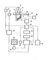
- the drawing diagrammatically shows an X-ray scanner which comprises an X-ray source 2, a detector 4 which is composed of a series of detector elements 6 which are adjacently arranged in a row and which may alternatively form a closed ring so that the detector need not be rotatable about an object 16, a high-voltage generator 8 and an object carrier 10 with a drive mechanism 12.
- the source 2 and the detector 4 of this embodiment are mounted on a common support 14 which enables the source and the detector to be rotated about the object 16 positioned on the object carrier.
- the apparatus comprises a detector read-out unit 18 which preferably includes a signal amplifier and an analog-to-digital converter.
- a control device 20 controls a control mechanism 22 which controls and effects the rotation of the source/detector support, the translation of the object carrier, and the control of the high-voltage generator.
- the control device is furthermore connected to a memory 24 and to a signal modulator 28 which is associated with a television monitor 26.
- arithmetic unit 30 For further signal processing there are provided an arithmetic unit 30, a selection device 32 and an image computing and reconstruction device 34.
- An apparatus of this kind is suitable for forming and recording a scan-derived sectional image at each of a succession of positions of the object carrier relative to the source and detector. All relevant measurement signals are processed in the detector read-out unit 18 and are applied, via the control device 20 for synchronization, to the arithmetic unit 30 for further processing, or are stored in the memory 24 for processing at a later stage. A series of successive scan-derived sectional images are used to form a three-dimensional matrix of absorption values from which a sectional image which can be displayed on the monitor, can be formed in known manner.
- the apparatus can be used to form scanograms by sliding the object carrier (preferably step-wise) through the support 14 with the rotation device in a locked condition.
- a location indicator 36 for example, as described in German Patent Specification 26 31 809, may be useful for locating each of the profiles with respect to a reference plane.
- image points which it is desired to select from the three-dimensional matrix of absorption values can be transferred to the scanogram, after which a scanogram thus treated can be displayed on the monitor.
- the selection of a region of interest to be transferred from the scan-derived images to the scanograms can be indicated, for example, by means of a light pen indicator 38, in a monitor display of each scan-derived sectional image.
- Other forms of interactive arrangements can alternatively be used for this purpose.
- the arithmetic unit also enables a selection to be made of one or more projection directions, i.e. a selection of one or more sets of profiles, each set relating to a fixed source/object direction, from each of a series of scan-derived sectional images, and to combine the profiles relating to a set so as to form a scanogram for the selected direction.
- both X-ray images and emission images can be made using the same apparatus; the latter images are made after injection of an appropriate radio-active tracer and correlation of these images in the-same display is again possible.
- a scanogram can thus be formed in which data obtained using the two methods is optimally combined.
- the possibility of exact positioning alternatively enables images recorded using different apparatus.for the different types of measurement, to be combined in a single display.
- the same object carrier would then be used for the various different forms of measurement.
- the source 2 in the described embodiment is, for example, a suitable high-voltage X-ray tube (approximately 350 V) to which the detector sensitivity is matched.
- excitation is provided by suitable electromagnetic coils with a corresponding form of detector device, and for ultrasound the source is formed by a high-frequency sound source with a detector in the form of a series of suitable transducers.
- both three-dimensional image matrices and scanograms can be formed by means of a radioactive tracer introduced into the patient.
- image data can then again be transferred from the three-dimensional image matrix to a scanogram or a similar type of synthetically formed general image.
Landscapes
- Health & Medical Sciences (AREA)
- Life Sciences & Earth Sciences (AREA)
- Engineering & Computer Science (AREA)
- Medical Informatics (AREA)
- Molecular Biology (AREA)
- Biomedical Technology (AREA)
- Biophysics (AREA)
- Veterinary Medicine (AREA)
- Public Health (AREA)
- Nuclear Medicine, Radiotherapy & Molecular Imaging (AREA)
- General Health & Medical Sciences (AREA)
- Pathology (AREA)
- Radiology & Medical Imaging (AREA)
- Physics & Mathematics (AREA)
- Heart & Thoracic Surgery (AREA)
- Animal Behavior & Ethology (AREA)
- Surgery (AREA)
- Pulmonology (AREA)
- Optics & Photonics (AREA)
- Theoretical Computer Science (AREA)
- High Energy & Nuclear Physics (AREA)
- Apparatus For Radiation Diagnosis (AREA)
- Ultra Sonic Daignosis Equipment (AREA)
Abstract
A radiation imaging apparatus for forming three-dimensional image matrices includes means for displaying image information therefrom in scanograms which are also formed by means of the apparatus. In a scanogram thus supplemented, selected subsidiary regions are reproduced with a high resolution obtained from the image matrices and suitably positioned with respect to the patient.
Description
- The invention relates to a radiation imaging apparatus, comprising a detector which is composed of a series of individually readable detector elements and which is rotatable about a patient table, either on its own or together with a radiation source, or which at least substantially surrounds the patient table, the patient table and at least the detector being arranged to be translatable with respect to one another.
- A radiography apparatus of this kind is known as an X-ray scanner from British Patent Specification 1,558,155. When an apparatus described therein is used for forming scanograms by means of computer calculation of absorption values, any anomalies present in the body under examination are usually only vague by defined and their positions are difficult to establish.
- A scanogram is to be understood to mean herein an image which is formed by moving an object and a detector with respect to one another in a longitudinal direction in an apparatus of the kind set forth with its rotation mechanism in a locked condition, and by recording for each location an edgewise shadowgraph image of a transaxial body section which will be called a profile, at a small distance from one another in a longitudinal direction. In principle, therefore, a scanogram is similar to a well-known shadowgraph image (radiographic), except that it is composed of a series of profiles. A profile is to be understood to mean herein a one-dimensional, flat shadowgraph image recorded from a fixed direction by means of a multi-element detector. An apparatus for forming scanograms and the advantages thereof are described in United States Patent Specification 3,101,407. When a sectional region of the object is measured in a plurality of source/detector positions which are angularly displaced about a rotation axis with respect to one another in order to form a scan-derived sectional image i.e. an image such as that customarily formed by an X-ray scanner, a scan-drived sectional image can be formed by the appropriate combination of measurement data thus obtained. A three-dimensional image matrix, also referred to as a scan-derived image, can be'formed from a series of scan-derived sectional images of consecutive planar sectional regions in an object. Measurements required to form a scan-derived sectional image will be, referred to hereinafter as a scan. It is to be noted that a profile can thus be made to constitute both to a scan-derived image and to a scanogram, so that it can supply data for the computation of a three-dimensional image matrix or data for a scanogram.
- For example, for therapy purposes the radiologist requires a scanogram in which any anomalies are shown with adequate contrast and accurately positioned within their environment.
- The invention has for its object to satisfy this requirement; to achieve this, a radiography apparatus of the kind set forth is characterized in that it comprises means for transferring image information from a three-dimensional image matrix to a scanogram.
- In an apparatus in accordance with the invention, measurement data which concern subsidiary regions, for example, a region containing an anomaly in a patient under examination, and whose position is known exactly and in which the contrast is high, can be transferred from an arbitrarily formed three-dimensional matrix image to a scanogram or another arbitrarily formed general image.
- Because a profile is an edge-projection of a scan-derived sectional image, areas in a scan-derived sectional image are thus reproduced in the profile as lines in the plane of the slice. In a scanogram a pattern of mutually parallel lines is thus formed, and when this is done in scanograms which are respectively formed using different projections, for example, one from front to back and another from one side to the other of a patient under examination, the anomaly can be unambiguously located. Obviously, this technique will also benefit the unambiguous location of an anomaly with respect to further structures in the body, for example, the location of an anomaly with respect to given bones or other suitably recognizable organs.
- A preferred embodiment of the apparatus is formed by an X-ray scanner in which the radiation source and the detector are arranged to be rotatable together about the object under examination, an object carrier being arranged to be axially translatable in exact defined steps with respect to the source/detector combination.
- In a further embodiment, the object under examination itself forms the radiation source, for example, a patient injected with a radioactive tracer, either only the detector being arranged to be rotatable with respect to the patient or the patient being surrounded almost completely by the detector.
- In a further embodiment, a memory/arithmetic unit added to the apparatus comprises means for selecting profiles from scan-derived sectional images in dependence on their projection directions in order to form a scanogram from a consecutive series of such profiles.
- Thus, the need for recording a scanogram together with the series of scan-derived images throughout a relevant part of a body under examination, is eliminated. Structures from scan-derived images can also be represented in a scanogram synthetically formed in this manner.
- Addition of stereotactic means to the apparatus enables the reproduction of the position and the direction of, for example, a surgical instrument, such as a needle, with respect to a marked target zone in a scano- gram filled with scan-derived image information according to the invention. An apparatus in accordance with the invention also enables radioactive tracer derived emission images and X-ray shadowgraph images of an object under examination to be correlated, so that data obtained by means of both methods can be presented in a single display.
- Even though the invention will be described mainly with reference to an X-ray scanner for producing both a thr:ee-dimensional image matrix and a scanogram, the invention is not restricted thereto. The three-dimensional image matrix, for example, can alternatively be formed by using ultrasound, nuclear magnetic resonance or compton scattering measurements. However, an accurate location correlation must always exist between the three-dimensional image matrix and the scanogram.
- Some preferred embodiments in accordance with the invention will be described in detail hereinafter with reference to the drawing. The drawing diagrammatically shows an X-ray scanner which comprises an
X-ray source 2, adetector 4 which is composed of a series ofdetector elements 6 which are adjacently arranged in a row and which may alternatively form a closed ring so that the detector need not be rotatable about anobject 16, a high-voltage generator 8 and anobject carrier 10 with adrive mechanism 12. Thesource 2 and thedetector 4 of this embodiment are mounted on a common support 14 which enables the source and the detector to be rotated about theobject 16 positioned on the object carrier. For reading the detector signals, the apparatus comprises a detector read-outunit 18 which preferably includes a signal amplifier and an analog-to-digital converter. - Under the control of processed detector signals, a
control device 20 controls acontrol mechanism 22 which controls and effects the rotation of the source/detector support, the translation of the object carrier, and the control of the high-voltage generator. The control device is furthermore connected to amemory 24 and to asignal modulator 28 which is associated with atelevision monitor 26. For further signal processing there are provided anarithmetic unit 30, aselection device 32 and an image computing andreconstruction device 34. - An apparatus of this kind is suitable for forming and recording a scan-derived sectional image at each of a succession of positions of the object carrier relative to the source and detector. All relevant measurement signals are processed in the detector read-out
unit 18 and are applied, via thecontrol device 20 for synchronization, to thearithmetic unit 30 for further processing, or are stored in thememory 24 for processing at a later stage. A series of successive scan-derived sectional images are used to form a three-dimensional matrix of absorption values from which a sectional image which can be displayed on the monitor, can be formed in known manner. In a manner similar to the method described in United States Patent Specification 3,101,407, the apparatus can be used to form scanograms by sliding the object carrier (preferably step-wise) through the support 14 with the rotation device in a locked condition. Alocation indicator 36, for example, as described inGerman Patent Specification 26 31 809, may be useful for locating each of the profiles with respect to a reference plane. Using the arithmetic device, image points which it is desired to select from the three-dimensional matrix of absorption values can be transferred to the scanogram, after which a scanogram thus treated can be displayed on the monitor. The selection of a region of interest to be transferred from the scan-derived images to the scanograms can be indicated, for example, by means of alight pen indicator 38, in a monitor display of each scan-derived sectional image. Other forms of interactive arrangements can alternatively be used for this purpose. The arithmetic unit also enables a selection to be made of one or more projection directions, i.e. a selection of one or more sets of profiles, each set relating to a fixed source/object direction, from each of a series of scan-derived sectional images, and to combine the profiles relating to a set so as to form a scanogram for the selected direction. - When the detector for measuring the X-rays in an apparatus in accordance with the invention is augmented by an adjacently mounted ring of detector elements for measuring, for example, gamma rays, both X-ray images and emission images can be made using the same apparatus; the latter images are made after injection of an appropriate radio-active tracer and correlation of these images in the-same display is again possible. A scanogram can thus be formed in which data obtained using the two methods is optimally combined. The possibility of exact positioning alternatively enables images recorded using different apparatus.for the different types of measurement, to be combined in a single display. Preferably, the same object carrier would then be used for the various different forms of measurement. For compton scattering measurements, the
source 2 in the described embodiment is, for example, a suitable high-voltage X-ray tube (approximately 350 V) to which the detector sensitivity is matched. For nuclear magnetic resonance measurements, excitation is provided by suitable electromagnetic coils with a corresponding form of detector device, and for ultrasound the source is formed by a high-frequency sound source with a detector in the form of a series of suitable transducers. Similarly, both three-dimensional image matrices and scanograms can be formed by means of a radioactive tracer introduced into the patient. In accordance with the invention, image data can then again be transferred from the three-dimensional image matrix to a scanogram or a similar type of synthetically formed general image.
Claims (10)
1. A radiation imaging apparatus, comprising a detector which is composed of a series of individually readable detector elements and which is rotatable about a patient, either on its own or together with a radiation source, or which at least substantially surrounds the patient table, the patient table and at least the detector being arranged to be translatable with respect to one another, characterized in that there are provided means for transferring image information from a three-dimensional image matrix to a scanogram.
2. A radiation imaging apparatus as claimed in Claim 1, characterized in that it is provided with an X-ray tube which is accommodated, together with the detector, in a support which is rotatable about the patient carrier, the patient carrier being translatable with respect to the support.
3. A radiation imaging apparatus as claimed in Claim 1, characterized in that the radiation to be measured is generated in a patient under examination, the detector being arranged to measure this radiation.
4. A radiation imaging apparatus as claimed in Claim 1, 2 or 3, characterized in that, in addition to the detector for measuring radiation emitted by an X-ray source and attenuated or scattered by a patient, .there is further provided a detector for measuring gamma radiation emitted by a patient.under examination.
5. A radiation imaging apparatus as claimed in any of the preceding Claims, characterized in that the patient carrier includes a drive mechanism for accurately defined, step-wise displacement of the patient carrier in a direction transverse to the planes of slices to be made.
6. A radiation imaging apparatus as claimed in any of the preceding Claims, characterized in that it comprises an arithmetic unit for selecting on the base of image orientation, profiles from scan-derived images and for composing a scanogram therefrom.
7. A radiation imaging apparatus as claimed in any of the preceding Claims, characterized in that for a simultaneous display of scanograms relating to different projection directions, a plurality of television monitors are provided.
8. A radiation imaging apparatus as claimed in Claim 1, 5, 6 or 7, characterized in. that the radiation source is formed by a high-frequency sound source, the detector being formed by a series of corresponding detector transducers.
9. A radiation imaging apparatus as claimed in Claim 1, 5, 6 or 7, characterized in that it is provided with a radiation source formed by an electromagnetic coil system for generating a magnetic alternating field in the MHz range, the detector being adapted to discriminate local differences in the radiation absorption in a patient.
10. A radiation imaging apparatus as claimed in Claim 1, 2, 5, 6 or 7, characterized in that it is provided with a high voltage X-ray tube, with a collimator for selecting a pencil like radiation beam detector being arranged to detect strong radiation occurring in a body to be examined.
Applications Claiming Priority (2)
| Application Number | Priority Date | Filing Date | Title |
|---|---|---|---|
| NL8003355A NL8003355A (en) | 1980-06-09 | 1980-06-09 | MEDICAL RADIATION EXAMINATION DEVICE. |
| NL8003355 | 1980-06-09 |
Publications (1)
| Publication Number | Publication Date |
|---|---|
| EP0041749A1 true EP0041749A1 (en) | 1981-12-16 |
Family
ID=19835442
Family Applications (1)
| Application Number | Title | Priority Date | Filing Date |
|---|---|---|---|
| EP81200564A Withdrawn EP0041749A1 (en) | 1980-06-09 | 1981-05-26 | Medical radiation imaging apparatus |
Country Status (4)
| Country | Link |
|---|---|
| EP (1) | EP0041749A1 (en) |
| JP (1) | JPS5722745A (en) |
| IL (1) | IL63050A0 (en) |
| NL (1) | NL8003355A (en) |
Cited By (4)
| Publication number | Priority date | Publication date | Assignee | Title |
|---|---|---|---|---|
| EP0129910A1 (en) * | 1983-06-27 | 1985-01-02 | Kabushiki Kaisha Toshiba | X-ray diagnostic apparatus for allowing stereoscopic visualization on X-ray images of an object under examination |
| EP0464645A1 (en) * | 1990-06-27 | 1992-01-08 | Kabushiki Kaisha Toshiba | Computed tomography scanner apparatus |
| US5978439A (en) * | 1997-02-14 | 1999-11-02 | U.S. Philips Corporation | X-ray imaging method involving a series of images from different perspectives |
| US10552664B2 (en) | 2017-11-24 | 2020-02-04 | International Business Machines Corporation | Image feature classification and localization using discriminative representations for robotic surgical control |
Families Citing this family (2)
| Publication number | Priority date | Publication date | Assignee | Title |
|---|---|---|---|---|
| JPS60160946A (en) * | 1984-02-02 | 1985-08-22 | 株式会社東芝 | X-ray ct apparatus |
| JPH0698126B2 (en) * | 1984-08-08 | 1994-12-07 | 株式会社東芝 | Display data processing device |
Citations (11)
| Publication number | Priority date | Publication date | Assignee | Title |
|---|---|---|---|---|
| US3101407A (en) * | 1959-04-09 | 1963-08-20 | Jr John Daniel Shipman | Fluoroscope system utilizing an image storage tube |
| DE1941433A1 (en) * | 1968-08-23 | 1970-02-26 | Emi Ltd | Method and device for examining a body by means of rays, for example X or gamma rays |
| DE2613809A1 (en) * | 1976-03-31 | 1977-10-06 | Siemens Ag | ROENTHINE LAYER FOR THE PRODUCTION OF TRANSVERSAL LAYER IMAGES |
| FR2352296A1 (en) * | 1976-05-19 | 1977-12-16 | Philips Nv | DEVICE FOR MEASURING THE DEGREE OF RADIATION ABSORPTION IN A PLANE OF A BODY |
| US4075700A (en) * | 1975-07-04 | 1978-02-21 | Emi Limited | Information display arrangements |
| US4086492A (en) * | 1976-01-21 | 1978-04-25 | Emi Limited | Display apparatus for use in radiography |
| DE2655661A1 (en) * | 1976-12-08 | 1978-06-15 | Siemens Ag | Radiation diagnosis instrument for transverse plane images - uses X=ray appts. with image amplifier and patient positioned on rolling table |
| US4179100A (en) * | 1977-08-01 | 1979-12-18 | University Of Pittsburgh | Radiography apparatus |
| US4196352A (en) * | 1978-04-28 | 1980-04-01 | General Electric Company | Multiple purpose high speed tomographic x-ray scanner |
| FR2435939A1 (en) * | 1978-07-24 | 1980-04-11 | Radiologie Cie Gle | METHOD FOR EXAMINING A PATIENT USING COMPUTER AND ULTRA-SOUND TECHNIQUES |
| EP0022722A1 (en) * | 1979-07-17 | 1981-01-21 | Thomson-Csf | Apparatus comprising an X-ray tomographic apparatus and a use of the apparatus for X-ray cinematography |
-
1980
- 1980-06-09 NL NL8003355A patent/NL8003355A/en not_active Application Discontinuation
-
1981
- 1981-05-26 EP EP81200564A patent/EP0041749A1/en not_active Withdrawn
- 1981-06-05 IL IL63050A patent/IL63050A0/en unknown
- 1981-06-06 JP JP8636581A patent/JPS5722745A/en active Pending
Patent Citations (12)
| Publication number | Priority date | Publication date | Assignee | Title |
|---|---|---|---|---|
| US3101407A (en) * | 1959-04-09 | 1963-08-20 | Jr John Daniel Shipman | Fluoroscope system utilizing an image storage tube |
| DE1941433A1 (en) * | 1968-08-23 | 1970-02-26 | Emi Ltd | Method and device for examining a body by means of rays, for example X or gamma rays |
| US4075700A (en) * | 1975-07-04 | 1978-02-21 | Emi Limited | Information display arrangements |
| US4086492A (en) * | 1976-01-21 | 1978-04-25 | Emi Limited | Display apparatus for use in radiography |
| DE2613809A1 (en) * | 1976-03-31 | 1977-10-06 | Siemens Ag | ROENTHINE LAYER FOR THE PRODUCTION OF TRANSVERSAL LAYER IMAGES |
| FR2345983A1 (en) * | 1976-03-31 | 1977-10-28 | Siemens Ag | TOMOGRAPHY DEVICE TO MAKE TRANSVERSAL TOMOGRAPHS |
| FR2352296A1 (en) * | 1976-05-19 | 1977-12-16 | Philips Nv | DEVICE FOR MEASURING THE DEGREE OF RADIATION ABSORPTION IN A PLANE OF A BODY |
| DE2655661A1 (en) * | 1976-12-08 | 1978-06-15 | Siemens Ag | Radiation diagnosis instrument for transverse plane images - uses X=ray appts. with image amplifier and patient positioned on rolling table |
| US4179100A (en) * | 1977-08-01 | 1979-12-18 | University Of Pittsburgh | Radiography apparatus |
| US4196352A (en) * | 1978-04-28 | 1980-04-01 | General Electric Company | Multiple purpose high speed tomographic x-ray scanner |
| FR2435939A1 (en) * | 1978-07-24 | 1980-04-11 | Radiologie Cie Gle | METHOD FOR EXAMINING A PATIENT USING COMPUTER AND ULTRA-SOUND TECHNIQUES |
| EP0022722A1 (en) * | 1979-07-17 | 1981-01-21 | Thomson-Csf | Apparatus comprising an X-ray tomographic apparatus and a use of the apparatus for X-ray cinematography |
Cited By (7)
| Publication number | Priority date | Publication date | Assignee | Title |
|---|---|---|---|---|
| EP0129910A1 (en) * | 1983-06-27 | 1985-01-02 | Kabushiki Kaisha Toshiba | X-ray diagnostic apparatus for allowing stereoscopic visualization on X-ray images of an object under examination |
| US4578802A (en) * | 1983-06-27 | 1986-03-25 | Kabushiki Kaisha Toshiba | X-ray diagnostic apparatus for allowing stereoscopic visualization on X-ray images of an object under examination |
| EP0464645A1 (en) * | 1990-06-27 | 1992-01-08 | Kabushiki Kaisha Toshiba | Computed tomography scanner apparatus |
| US5212717A (en) * | 1990-06-27 | 1993-05-18 | Kabushiki Kaisha Toshiba | Computed tomography scanner apparatus |
| EP0744158A3 (en) * | 1990-06-27 | 1997-05-14 | Toshiba Kk | Computed tomography scanner apparatus |
| US5978439A (en) * | 1997-02-14 | 1999-11-02 | U.S. Philips Corporation | X-ray imaging method involving a series of images from different perspectives |
| US10552664B2 (en) | 2017-11-24 | 2020-02-04 | International Business Machines Corporation | Image feature classification and localization using discriminative representations for robotic surgical control |
Also Published As
| Publication number | Publication date |
|---|---|
| JPS5722745A (en) | 1982-02-05 |
| NL8003355A (en) | 1982-01-04 |
| IL63050A0 (en) | 1981-09-13 |
Similar Documents
| Publication | Publication Date | Title |
|---|---|---|
| US5762608A (en) | Scanning x-ray imaging system with rotating c-arm | |
| JP2515973B2 (en) | Projection radiographic system and radiation detector | |
| Greitz et al. | Head fixation system for integration of radiodiagnostic and therapeutic procedures | |
| US4923459A (en) | Stereotactics apparatus | |
| US3927318A (en) | Cross-sectional fluorescent imaging system | |
| US6079876A (en) | X-ray exposure system for 3D imaging | |
| US4118631A (en) | Radiographic apparatus | |
| US4229651A (en) | Radiation scanning method and apparatus | |
| US4573179A (en) | Scanned projection radiography using high speed computed tomographic scanning system | |
| JPH0228818B2 (en) | ||
| JPS6246171B1 (en) | ||
| US20020067793A1 (en) | Computer tomography unit and method for operating same | |
| US4433427A (en) | Method and apparatus for examining a body by means of penetrating radiation such as X-rays | |
| US6792068B1 (en) | Computed tomography device with a multi-line detector system | |
| US8971991B2 (en) | Supplemental transmission information for attenuation correction in positron emission tomography imaging | |
| US4138611A (en) | Fan beam CT apparatus with post-processing weighting of picture element signals | |
| EP0041749A1 (en) | Medical radiation imaging apparatus | |
| JPH05344964A (en) | CT device | |
| US6249003B1 (en) | Imaging attenuation correction method employing multiple energy scan masks and windows | |
| US20040260171A1 (en) | Combined tomography and radiographic projection system | |
| EP4218590B1 (en) | Computed tomography device and driving method thereof | |
| Suramo et al. | A low-dose CT-pelvimetry | |
| Sashin et al. | Computer electronic radiography for early detection of vascular disease | |
| GB1571489A (en) | Computerised tomography | |
| RU2103920C1 (en) | Computer tomograph |
Legal Events
| Date | Code | Title | Description |
|---|---|---|---|
| PUAI | Public reference made under article 153(3) epc to a published international application that has entered the european phase |
Free format text: ORIGINAL CODE: 0009012 |
|
| AK | Designated contracting states |
Designated state(s): DE FR GB NL |
|
| 17P | Request for examination filed |
Effective date: 19820114 |
|
| RAP1 | Party data changed (applicant data changed or rights of an application transferred) |
Owner name: N.V. PHILIPS' GLOEILAMPENFABRIEKEN |
|
| STAA | Information on the status of an ep patent application or granted ep patent |
Free format text: STATUS: THE APPLICATION IS DEEMED TO BE WITHDRAWN |
|
| 18D | Application deemed to be withdrawn |
Effective date: 19830414 |
|
| RIN1 | Information on inventor provided before grant (corrected) |
Inventor name: ZONNEVELD, FRANS WESSEL |