EP0040103B1 - Resin impregnator - Google Patents
Resin impregnator Download PDFInfo
- Publication number
- EP0040103B1 EP0040103B1 EP19810302120 EP81302120A EP0040103B1 EP 0040103 B1 EP0040103 B1 EP 0040103B1 EP 19810302120 EP19810302120 EP 19810302120 EP 81302120 A EP81302120 A EP 81302120A EP 0040103 B1 EP0040103 B1 EP 0040103B1
- Authority
- EP
- European Patent Office
- Prior art keywords
- disc
- resin
- filaments
- mandrel
- guide
- Prior art date
- Legal status (The legal status is an assumption and is not a legal conclusion. Google has not performed a legal analysis and makes no representation as to the accuracy of the status listed.)
- Expired
Links
- 239000011347 resin Substances 0.000 title claims description 46
- 229920005989 resin Polymers 0.000 title claims description 46
- 238000009987 spinning Methods 0.000 claims description 10
- 238000004519 manufacturing process Methods 0.000 claims description 3
- 238000005470 impregnation Methods 0.000 description 5
- 238000000034 method Methods 0.000 description 4
- 238000004140 cleaning Methods 0.000 description 3
- OKTJSMMVPCPJKN-UHFFFAOYSA-N Carbon Chemical compound [C] OKTJSMMVPCPJKN-UHFFFAOYSA-N 0.000 description 2
- 229910052799 carbon Inorganic materials 0.000 description 2
- 230000000694 effects Effects 0.000 description 2
- 150000002118 epoxides Chemical class 0.000 description 2
- 239000011521 glass Substances 0.000 description 2
- 239000004848 polyfunctional curative Substances 0.000 description 2
- 239000011148 porous material Substances 0.000 description 2
- 238000003860 storage Methods 0.000 description 2
- 239000011248 coating agent Substances 0.000 description 1
- 238000000576 coating method Methods 0.000 description 1
- 238000004891 communication Methods 0.000 description 1
- 239000003822 epoxy resin Substances 0.000 description 1
- 239000000835 fiber Substances 0.000 description 1
- 230000005484 gravity Effects 0.000 description 1
- 239000007788 liquid Substances 0.000 description 1
- 229920000647 polyepoxide Polymers 0.000 description 1
- 229920000728 polyester Polymers 0.000 description 1
- 238000005086 pumping Methods 0.000 description 1
- 239000003829 resin cement Substances 0.000 description 1
- 239000007921 spray Substances 0.000 description 1
- 238000005507 spraying Methods 0.000 description 1
- 238000004804 winding Methods 0.000 description 1
Images

Classifications
-
- B—PERFORMING OPERATIONS; TRANSPORTING
- B29—WORKING OF PLASTICS; WORKING OF SUBSTANCES IN A PLASTIC STATE IN GENERAL
- B29B—PREPARATION OR PRETREATMENT OF THE MATERIAL TO BE SHAPED; MAKING GRANULES OR PREFORMS; RECOVERY OF PLASTICS OR OTHER CONSTITUENTS OF WASTE MATERIAL CONTAINING PLASTICS
- B29B15/00—Pretreatment of the material to be shaped, not covered by groups B29B7/00 - B29B13/00
- B29B15/08—Pretreatment of the material to be shaped, not covered by groups B29B7/00 - B29B13/00 of reinforcements or fillers
- B29B15/10—Coating or impregnating independently of the moulding or shaping step
- B29B15/12—Coating or impregnating independently of the moulding or shaping step of reinforcements of indefinite length
- B29B15/122—Coating or impregnating independently of the moulding or shaping step of reinforcements of indefinite length with a matrix in liquid form, e.g. as melt, solution or latex
- B29B15/127—Coating or impregnating independently of the moulding or shaping step of reinforcements of indefinite length with a matrix in liquid form, e.g. as melt, solution or latex by spraying
Definitions
- This invention relates to apparatus for applying resin to filaments to be used for forming filament-reinforced resin pipes, tubes or other cylindrical bodies.
- filament-reinforced resin pipes In the manufacture of filament-reinforced resin pipes by the sheath process, flat rovings of filaments are wound tangentially onto a rotating and translating mandrel.
- filaments and resins A variety of filaments and resins may be used but the filaments are usually glass or carbon filaments and the resins polyesters or epoxides.
- each filament Prior to winding the filaments are impregnated with resin and for efficient operation each filament should receive the same controlled amount of resin.
- An alternative method is to feed the filaments through resin baths disposed on either side of the machine and then to guide the filaments onto the mandrel.
- This system also has disadvantages viz:
- Filament-reinforced pipes may also be manufactured on mandrels which translate but do not rotate in which case the filaments run parallel to the axis of the pipe and are cemented to form a pipe.
- Carbon-fibre reinforced pipes may be made in this way, the resin cement being an epoxide. Similar problems of coating the filament with a controlled and uniform amount of resin arise with such axially aligned filament-reinforced pipes as they do with tangentially wound pipes.
- the present invention aims to overcome the disadvantages of known systems by spraying resin onto the filaments using a spinning disc.
- apparatus for impregnating filaments with resin comprises:-
- the axis of the guide, disc and mandrel may be in any direction, but in current machines the mandrel axis is usually horizontal, and this is preferred with the present invention.
- Existing machines may readily be adapted by replacing existing impregnation equipment with the present apparatus.
- the mandrel may both translate and rotate for tangentially wound pipes or may translate without rotation for axially aligned pipes.
- the fixed annular guide may be shaped and positioned to give a smooth feed of filaments from their storage reels onto the mandrel without abrupt changes of direction. Thus it may be a truncated cone which may be of a relatively large diameter with respect to the mandrel and shallow in depth.
- the spinning disc may be positioned on a fixed sleeve surrounding the mandrel and part of this fixed sleeve may also act as part of the guide.
- the spinning disc may be positioned on a fixed sleeve and surrounding the mandrel and separated from it by a gap or by suitable bearings.
- the form of the disc is not critical and may vary from a flat annular disc through hollow cones of varying included angles to an annular cylinder.
- resin may be fed to the smaller end of a truncated cone where there may be a reservoir. Centrifugal force carries the resin along the inside of the cone to the periphery from where it is thrown off as a corona onto the filaments passing into the annular guide.
- the reservoir may be smaller or non-existent but again centrifugal force will carry the resin along the surface of the disc to the periphery of the disc.
- the form in which the resin is discharged from the periphery of the disc is not critical (i.e. the resin may be discharged as a sheet or as droplets) and it is not necessary for the periphery of the disc to be serrated as with atomising discs.
- the speed of rotation is not critical and, in general, resin is discharged at the rate at which it is fed. This means that the amount of resin applied to the filaments can be simply controlled by the rate of supply of resin to the disc. There is no need for a large reservoir of liquid to be on the disc at any time so supply to and cut-off of resin from the filaments can be almost instantaneous.
- filament-reinforced pipes may have from 40-60% of their volume as filaments and the resin feed rate can be simply calculated once the feed rate of the filaments is known.
- the spinning disc surrounds the mandrel with the filaments outside the disc so in' practice the filaments will be in the form of a cone of filaments or rovings of filaments moving tangentially onto the mandrel at a point some distance along the axis of the mandrel from the spinning disc. This facilitates start-up and shut-down of the machine and allows time for the resin to impregnate the
- the disc can be driven in any convenient manner, e.g. by an electric motor through gearing and the resin can also be delivered to the disc in any convenient manner, e.g. by an electrically driven pump.
- the whole assembly may be mounted on suitable supporting brackets.
- a filament-reinforced resin pipe manufacturing machine has a rotating and translating mandrel D which, although shown vertically, has in fact a horizontal axis of rotation.
- a fixed support ring 8 Surrounding the mandrel D is a fixed support ring 8 and bracket 9 bolted to ring 8 by bolts, one of which is shown at 22.
- the bracket 9 in its turn is bolted onto the machine framework 25 by three bolts positioned at 120° around.the machine. One bolt is shown at 26.
- Support ring 8 has a sleeve 1 bolted to it by bolts, one of which is shown at 21.
- Sleeve 1 terminates in a filament guide ring 3 attached to the sleeve by screws, one of which is shown at 19.
- a rotatable annular shaft 2 Surrounding sleeve 1 is a rotatable annular shaft 2, separated from sleeve 1 by bearings 10 and 11. Mounted on shaft 2 by screws, one of which is shown at 24, is a spinning disc 4 in the form of a hollow, inverted, truncated cone.
- the disc 4 has an annular reservoir E which may be supplied with resin by pipe 17, held onto support ring 8 by nuts 16.
- the screws 24 (of which there are eight) holding disc 4 onto shaft 2 pass through spacing pieces 18 (see Figure 2). Thus, except at these eight screw points, reservoir E is in communication with the inside of the cone of the disc.
- Shaft 2 has a gear ring 7 bolted onto it by bolts, one of which is shown at 23.
- Gear ring 7 meshes with pinion 5 fixed by screw 15 to the drive shaft of an electric motor 12, held onto support ring 8 by bolts, one of which is shown at 13.
- the drive shaft rotates in a bearing 14 in support ring 8.
- the machine framework 25 has outer and inner eyelet rings B and C and the framework also has bolted to it filament guide ring 6, one bolt being shown at 20.
- rovings of filaments are fed from path A through eyelets B and C onto mandrel D, passing through the annulus between fixed filament guides 3 and 6. As they pass over filament guide 6 the rovings receive an annular spray of resin from disc 4, the resin being moved by centrifugal force from reservoir E along the inner conical surface of the disc. Control of the resin feed controls the supply of resin to the filaments.
- the apparatus may be cleaned by removing the three bolts 26, thus exposing disc 4 and guides 3 and 6.
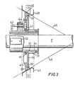
- Figure 3 the arrangement of the parts is generally similar to Figure 1 the main differences being that the mandrel translates but does not rotate and the disc is a flat annular disc rather than a truncated cone.
- Translating, non-rotating mandrel F is surrounded by a fixed sleeve 31 held onto the machine frame by brackets 32.
- a rotatable sleeve 35 Surrounding one end of sleeve 31 and separated from it by bearings 33, 34 is a rotatable sleeve 35 to which is welded at right angles a flat disc 36.
- Bolted to disc 36 by bolts 37 is a ring 38 having a small reservoir 39 and a chamfered periphery 40.
- the sleeve 35, disc 36 and ring 38 together form the resin applying disc and they are rotated through gears 41 and 42.
- the drive to gear 42 is through shaft 43 from an electric motor (not shown).
- Shaft 43 is held in bearings 44 fixed to sleeve 31.
- Adjacent to and surrounding the chamfered periphery 40 of ring 38 is an annular conical guide 45 fixed to a convenient part of the machine (not shown). Filaments 46 are fed from reels or other storage means (not shown) onto the mandrel F between guide 45 and the chamfered periphery 40.
- resin is injected from a nozzle (not shown) into reservoir 39 of the ring portion 38 of the spinning disc through the opening 47.
- resin already in the reservoir flows out of the opening 47 and is carried by centrifugal force along the surface of ring 38 to the periphery 40 and onto filaments 46 passing between the ring 38 and fixed guide 45.
- the apparatus may be cleaned by moving fixed sleeve 31 to the left on runners (not shown) thus exposing ring 38 and guide 45.
- 120 glass filaments of 600 tex were fed tangentially onto a rotating and translating mandrel.
- the linear speed of the filaments as they passed the spinning disc was 400 cm/sec.
- the disc was rotated at 600 rpm and epoxide resin was fed to the disc at a rate of 9 ml/sec.
- the resulting pipe has a filament volume of 55%.
- the apparatus thus has the following advantages over existing impregnation equipment:
Landscapes
- Engineering & Computer Science (AREA)
- Mechanical Engineering (AREA)
- Moulding By Coating Moulds (AREA)
Description
- This invention relates to apparatus for applying resin to filaments to be used for forming filament-reinforced resin pipes, tubes or other cylindrical bodies.
- In the manufacture of filament-reinforced resin pipes by the sheath process, flat rovings of filaments are wound tangentially onto a rotating and translating mandrel. A variety of filaments and resins may be used but the filaments are usually glass or carbon filaments and the resins polyesters or epoxides.
- Prior to winding the filaments are impregnated with resin and for efficient operation each filament should receive the same controlled amount of resin.
- One known method of impregnation is to pass the filaments through an annular guide ring of porous material, which acts in effect as a wick to transfer resin to the filaments. The disadvantages of this method are:-
- (a) unequal impregnation due to gravity effects,
- (b) possible damage to the filaments by rubbing contact with the porous guide, and
- (c) the need to replace the porous material after each run since it becomes clogged with hardened resin.
- An alternative method is to feed the filaments through resin baths disposed on either side of the machine and then to guide the filaments onto the mandrel. This system also has disadvantages viz:
- (a) a number of baths are required depending on the number of rovings and their radial disposition,
- (b) wet filaments have to pass round guides to guide them into the radial path,
- (c) threading up before a run and cleaning after it presents considerable problems, and
- (d) the tension varies from filament to filament due to unequal path lengths.
- Filament-reinforced pipes may also be manufactured on mandrels which translate but do not rotate in which case the filaments run parallel to the axis of the pipe and are cemented to form a pipe. Carbon-fibre reinforced pipes may be made in this way, the resin cement being an epoxide. Similar problems of coating the filament with a controlled and uniform amount of resin arise with such axially aligned filament-reinforced pipes as they do with tangentially wound pipes.
- The present invention aims to overcome the disadvantages of known systems by spraying resin onto the filaments using a spinning disc.
- According to the present invention apparatus for impregnating filaments with resin comprises:-
- (i) a fixed annular guide adapted to feed filaments onto a translating mandrel, said guide being co-axial with the mandrel,
- (ii) an annular spinning disc also co-axial with the mandrel and positioned so that the periphery of the disc is adjacent to the guide,
- (iii) means for rotating the disc, and
- (iv) means capable of feeding resin to the disc in a controllable amount.
- The axis of the guide, disc and mandrel may be in any direction, but in current machines the mandrel axis is usually horizontal, and this is preferred with the present invention. Existing machines may readily be adapted by replacing existing impregnation equipment with the present apparatus.
- The mandrel may both translate and rotate for tangentially wound pipes or may translate without rotation for axially aligned pipes. The fixed annular guide may be shaped and positioned to give a smooth feed of filaments from their storage reels onto the mandrel without abrupt changes of direction. Thus it may be a truncated cone which may be of a relatively large diameter with respect to the mandrel and shallow in depth. As discussed hereafter, the spinning disc may be positioned on a fixed sleeve surrounding the mandrel and part of this fixed sleeve may also act as part of the guide.
- The spinning disc may be positioned on a fixed sleeve and surrounding the mandrel and separated from it by a gap or by suitable bearings. The form of the disc is not critical and may vary from a flat annular disc through hollow cones of varying included angles to an annular cylinder. In the case of conical discs, resin may be fed to the smaller end of a truncated cone where there may be a reservoir. Centrifugal force carries the resin along the inside of the cone to the periphery from where it is thrown off as a corona onto the filaments passing into the annular guide.
- With a flat annular disc the reservoir may be smaller or non-existent but again centrifugal force will carry the resin along the surface of the disc to the periphery of the disc.
- It has been found that the form in which the resin is discharged from the periphery of the disc is not critical (i.e. the resin may be discharged as a sheet or as droplets) and it is not necessary for the periphery of the disc to be serrated as with atomising discs. Further, the speed of rotation is not critical and, in general, resin is discharged at the rate at which it is fed. This means that the amount of resin applied to the filaments can be simply controlled by the rate of supply of resin to the disc. There is no need for a large reservoir of liquid to be on the disc at any time so supply to and cut-off of resin from the filaments can be almost instantaneous.
- In general filament-reinforced pipes may have from 40-60% of their volume as filaments and the resin feed rate can be simply calculated once the feed rate of the filaments is known.
- The spinning disc surrounds the mandrel with the filaments outside the disc so in' practice the filaments will be in the form of a cone of filaments or rovings of filaments moving tangentially onto the mandrel at a point some distance along the axis of the mandrel from the spinning disc. This facilitates start-up and shut-down of the machine and allows time for the resin to impregnate the
- rovings thoroughly before being formed into a pipe on the mandrel.
- The disc can be driven in any convenient manner, e.g. by an electric motor through gearing and the resin can also be delivered to the disc in any convenient manner, e.g. by an electrically driven pump.
- The whole assembly may be mounted on suitable supporting brackets.
- The invention is illustrated with reference to the accompanying drawings in which:
- Figure 1 is a section through an apparatus according to the invention used for making tangentially-wound filament-reinforced pipes,
- Figure 2 is a part section along the line X-X of Figure 1, and
- Figure 3 is a section through an apparatus according to the invention for making axially aligned filament-reinforced pipes.
- In Figures 1 and 2 a filament-reinforced resin pipe manufacturing machine has a rotating and translating mandrel D which, although shown vertically, has in fact a horizontal axis of rotation. Surrounding the mandrel D is a
fixed support ring 8 andbracket 9 bolted to ring 8 by bolts, one of which is shown at 22. Thebracket 9 in its turn is bolted onto themachine framework 25 by three bolts positioned at 120° around.the machine. One bolt is shown at 26. -
Support ring 8 has a sleeve 1 bolted to it by bolts, one of which is shown at 21. Sleeve 1 terminates in a filament guide ring 3 attached to the sleeve by screws, one of which is shown at 19. - Surrounding sleeve 1 is a rotatable
annular shaft 2, separated from sleeve 1 bybearings shaft 2 by screws, one of which is shown at 24, is aspinning disc 4 in the form of a hollow, inverted, truncated cone. Thedisc 4 has an annular reservoir E which may be supplied with resin bypipe 17, held ontosupport ring 8 bynuts 16. The screws 24 (of which there are eight) holdingdisc 4 ontoshaft 2 pass through spacing pieces 18 (see Figure 2). Thus, except at these eight screw points, reservoir E is in communication with the inside of the cone of the disc. - Shaft 2 has a gear ring 7 bolted onto it by bolts, one of which is shown at 23. Gear ring 7 meshes with
pinion 5 fixed byscrew 15 to the drive shaft of anelectric motor 12, held ontosupport ring 8 by bolts, one of which is shown at 13. The drive shaft rotates in abearing 14 insupport ring 8. - The
machine framework 25 has outer and inner eyelet rings B and C and the framework also has bolted to it filament guide ring 6, one bolt being shown at 20. - In operation, rovings of filaments are fed from path A through eyelets B and C onto mandrel D, passing through the annulus between fixed filament guides 3 and 6. As they pass over filament guide 6 the rovings receive an annular spray of resin from
disc 4, the resin being moved by centrifugal force from reservoir E along the inner conical surface of the disc. Control of the resin feed controls the supply of resin to the filaments. - At the end of a run the apparatus may be cleaned by removing the three
bolts 26, thus exposingdisc 4 and guides 3 and 6. - In Figure 3, the arrangement of the parts is generally similar to Figure 1 the main differences being that the mandrel translates but does not rotate and the disc is a flat annular disc rather than a truncated cone.
- Translating, non-rotating mandrel F is surrounded by a fixed
sleeve 31 held onto the machine frame bybrackets 32. Surrounding one end ofsleeve 31 and separated from it bybearings rotatable sleeve 35 to which is welded at right angles aflat disc 36. Bolted todisc 36 by bolts 37 is a ring 38 having asmall reservoir 39 and achamfered periphery 40. Thesleeve 35,disc 36 and ring 38 together form the resin applying disc and they are rotated throughgears 41 and 42. The drive to gear 42 is throughshaft 43 from an electric motor (not shown).Shaft 43 is held inbearings 44 fixed tosleeve 31. - Adjacent to and surrounding the chamfered
periphery 40 of ring 38 is an annularconical guide 45 fixed to a convenient part of the machine (not shown).Filaments 46 are fed from reels or other storage means (not shown) onto the mandrel F betweenguide 45 and the chamferedperiphery 40. - In operation resin is injected from a nozzle (not shown) into
reservoir 39 of the ring portion 38 of the spinning disc through theopening 47. As further resin is injected, resin already in the reservoir flows out of theopening 47 and is carried by centrifugal force along the surface of ring 38 to theperiphery 40 and ontofilaments 46 passing between the ring 38 and fixedguide 45. - At the end of a run the apparatus may be cleaned by moving fixed
sleeve 31 to the left on runners (not shown) thus exposing ring 38 andguide 45. - In one specific example using the apparatus of Figure 1, 120 glass filaments of 600 tex were fed tangentially onto a rotating and translating mandrel. The linear speed of the filaments as they passed the spinning disc was 400 cm/sec. The disc was rotated at 600 rpm and epoxide resin was fed to the disc at a rate of 9 ml/sec. The resulting pipe has a filament volume of 55%.
- In another specific example using the apparatus of Figure 3, 270 carbon filaments were fed axially onto a translating but non-rotating mandrel. The linear speed of the filaments passing the discs was 3 cm/sec, the rotational speed of the disc was rpm, and the resin feed rate to the disc was 4 ml/sec. The resulting pipe had a filament volume of 50%.
- The apparatus thus has the following advantages over existing impregnation equipment:-
- (i) Even impregnation of resin over the full 360° of filaments around a mandrel.
- (ii) Resin supply is controllable by simply altering the pumping rate. The response can be virtually instantaneous and resin supply can be metered down to zero flow.
- (iii) The risk of filament damage is minimised. There are no porous guides and all guides can be smooth and polished.
- (iv) Easy cleaning procedure at the end of a run.
- (v) Resin and hardener can be mixed immediately prior to being fed onto the disc. The volume of mixed resin/hardener in the system may be small and cleaning and "pot life" problems are reduced.
Claims (6)
Applications Claiming Priority (2)
| Application Number | Priority Date | Filing Date | Title |
|---|---|---|---|
| GB8015937 | 1980-05-14 | ||
| GB8015937 | 1980-05-14 |
Publications (3)
| Publication Number | Publication Date |
|---|---|
| EP0040103A2 EP0040103A2 (en) | 1981-11-18 |
| EP0040103A3 EP0040103A3 (en) | 1983-01-26 |
| EP0040103B1 true EP0040103B1 (en) | 1985-04-10 |
Family
ID=10513418
Family Applications (1)
| Application Number | Title | Priority Date | Filing Date |
|---|---|---|---|
| EP19810302120 Expired EP0040103B1 (en) | 1980-05-14 | 1981-05-13 | Resin impregnator |
Country Status (2)
| Country | Link |
|---|---|
| EP (1) | EP0040103B1 (en) |
| DE (1) | DE3169794D1 (en) |
Family Cites Families (4)
| Publication number | Priority date | Publication date | Assignee | Title |
|---|---|---|---|---|
| NL6411933A (en) * | 1964-10-14 | 1966-04-15 | ||
| DE1914344A1 (en) * | 1969-01-14 | 1970-10-01 | Kabel Metallwerke Ghh | Process for the continuous production of metal pipes coated with plastic on the inside |
| US3934821A (en) * | 1974-05-06 | 1976-01-27 | Paul Mueller Company | Bulk cooler and storage tank |
| DE2808903A1 (en) * | 1978-03-02 | 1979-09-06 | Karl Reinhard Zeiss | Plastics coating applicator for internal pipe wall - esp. in printing rate mfr., contains phosphoric acid, potassium permanganate and dispersed inorganic thickener |
-
1981
- 1981-05-13 DE DE8181302120T patent/DE3169794D1/en not_active Expired
- 1981-05-13 EP EP19810302120 patent/EP0040103B1/en not_active Expired
Also Published As
| Publication number | Publication date |
|---|---|
| EP0040103A3 (en) | 1983-01-26 |
| EP0040103A2 (en) | 1981-11-18 |
| DE3169794D1 (en) | 1985-05-15 |
Similar Documents
| Publication | Publication Date | Title |
|---|---|---|
| US4494436A (en) | Apparatus for manufacturing resin impregnated fiber braided products | |
| US4172562A (en) | Process for winding filaments on a mandrel | |
| KR0133063B1 (en) | Method and apparatus for manufacturing yarn or strip made of reinforcing fibers and thermoplastic organics | |
| FI79691B (en) | FOERBAETTRINGAR AV ANORDNINGAR FOER FRAMSTAELLNING AV MINERALFIBRER MED HJAELP AV CENTRIFUGALHJUL. | |
| US2728972A (en) | Method and apparatus for coating fibers | |
| US5088831A (en) | Device for treating material mixtures | |
| US2168917A (en) | Apparatus for coating pipes and the like | |
| US4482420A (en) | Apparatus for producing composite pipes | |
| US4361459A (en) | Resin impregnator for filament wound pipe | |
| US3293013A (en) | Method of and apparatus for feeding a substantially untwisted multifilament strand | |
| US3791900A (en) | Process and apparatus for the production of hollow bodies from reaction resins, which are reinforced with fibres | |
| CA1114688A (en) | Apparatus for at least partly removing adhering liquid from and/or evenly distributing liquid over the surface of articles | |
| US2993526A (en) | Apparatus and method of making hollow elongated plastic products | |
| EP0040103A2 (en) | Resin impregnator | |
| US3627601A (en) | Method of forming a filament wound tube with an inner wall having high-wear resistance | |
| WO1999059730A1 (en) | Method and device for applying a plastic layer to the inner surfaces of hollow bodies | |
| US3357807A (en) | Method and apparatus for forming and processing continuous filaments | |
| US2398808A (en) | Apparatus for forming fibrous strands | |
| US2187094A (en) | Apparatus for spinning and winding glass filaments | |
| RU2192351C2 (en) | Method and device for manufacture of extruded article and extruded article | |
| FI60688C (en) | APPARAT FOER SAMLING AV LINJAERT MATERIAL TILL SPOLAR | |
| US2691852A (en) | Method and apparatus for producing fibers | |
| US5756149A (en) | Method and apparatus for lubricating continuous fiber strand winding apparatus | |
| US2865324A (en) | Apparatus for applying coating material to articles | |
| US3628931A (en) | Apparatus having rotating bushing for forming fibers |
Legal Events
| Date | Code | Title | Description |
|---|---|---|---|
| PUAI | Public reference made under article 153(3) epc to a published international application that has entered the european phase |
Free format text: ORIGINAL CODE: 0009012 |
|
| AK | Designated contracting states |
Designated state(s): DE FR GB IT |
|
| 17P | Request for examination filed |
Effective date: 19811103 |
|
| PUAL | Search report despatched |
Free format text: ORIGINAL CODE: 0009013 |
|
| AK | Designated contracting states |
Designated state(s): DE FR GB IT |
|
| ITF | It: translation for a ep patent filed | ||
| GRAA | (expected) grant |
Free format text: ORIGINAL CODE: 0009210 |
|
| AK | Designated contracting states |
Designated state(s): DE FR GB IT |
|
| REF | Corresponds to: |
Ref document number: 3169794 Country of ref document: DE Date of ref document: 19850515 |
|
| ET | Fr: translation filed | ||
| PLBE | No opposition filed within time limit |
Free format text: ORIGINAL CODE: 0009261 |
|
| STAA | Information on the status of an ep patent application or granted ep patent |
Free format text: STATUS: NO OPPOSITION FILED WITHIN TIME LIMIT |
|
| 26N | No opposition filed | ||
| ITTA | It: last paid annual fee | ||
| PGFP | Annual fee paid to national office [announced via postgrant information from national office to epo] |
Ref country code: DE Payment date: 19910320 Year of fee payment: 11 |
|
| PGFP | Annual fee paid to national office [announced via postgrant information from national office to epo] |
Ref country code: FR Payment date: 19910322 Year of fee payment: 11 |
|
| PGFP | Annual fee paid to national office [announced via postgrant information from national office to epo] |
Ref country code: GB Payment date: 19910417 Year of fee payment: 11 |
|
| PG25 | Lapsed in a contracting state [announced via postgrant information from national office to epo] |
Ref country code: GB Effective date: 19920513 |
|
| GBPC | Gb: european patent ceased through non-payment of renewal fee |
Effective date: 19920513 |
|
| PG25 | Lapsed in a contracting state [announced via postgrant information from national office to epo] |
Ref country code: FR Effective date: 19930129 |
|
| PG25 | Lapsed in a contracting state [announced via postgrant information from national office to epo] |
Ref country code: DE Effective date: 19930202 |
|
| REG | Reference to a national code |
Ref country code: FR Ref legal event code: ST |