EP0039623B1 - Improvements in or relating to scroll-type fluid displacement apparatus - Google Patents
Improvements in or relating to scroll-type fluid displacement apparatus Download PDFInfo
- Publication number
- EP0039623B1 EP0039623B1 EP81302013A EP81302013A EP0039623B1 EP 0039623 B1 EP0039623 B1 EP 0039623B1 EP 81302013 A EP81302013 A EP 81302013A EP 81302013 A EP81302013 A EP 81302013A EP 0039623 B1 EP0039623 B1 EP 0039623B1
- Authority
- EP
- European Patent Office
- Prior art keywords
- end plate
- cup
- shaped casing
- scroll member
- projection
- Prior art date
- Legal status (The legal status is an assumption and is not a legal conclusion. Google has not performed a legal analysis and makes no representation as to the accuracy of the status listed.)
- Expired
Links
- 239000012530 fluid Substances 0.000 title claims description 42
- 238000006073 displacement reaction Methods 0.000 title claims description 10
- 230000007246 mechanism Effects 0.000 claims description 12
- 230000002093 peripheral effect Effects 0.000 claims description 11
- 230000000694 effects Effects 0.000 claims description 3
- 238000000926 separation method Methods 0.000 claims description 3
- 239000003507 refrigerant Substances 0.000 description 4
- 229910000831 Steel Inorganic materials 0.000 description 3
- XAGFODPZIPBFFR-UHFFFAOYSA-N aluminium Chemical compound [Al] XAGFODPZIPBFFR-UHFFFAOYSA-N 0.000 description 3
- 229910052782 aluminium Inorganic materials 0.000 description 3
- 239000010959 steel Substances 0.000 description 3
- 239000004411 aluminium Substances 0.000 description 2
- 238000010276 construction Methods 0.000 description 2
- 238000004512 die casting Methods 0.000 description 2
- 230000004048 modification Effects 0.000 description 2
- 238000012986 modification Methods 0.000 description 2
- 238000007789 sealing Methods 0.000 description 2
- 229910000838 Al alloy Inorganic materials 0.000 description 1
- 238000006243 chemical reaction Methods 0.000 description 1
- 230000006835 compression Effects 0.000 description 1
- 238000007906 compression Methods 0.000 description 1
- 238000001816 cooling Methods 0.000 description 1
- 230000007423 decrease Effects 0.000 description 1
- 238000010586 diagram Methods 0.000 description 1
- ZZUFCTLCJUWOSV-UHFFFAOYSA-N furosemide Chemical compound C1=C(Cl)C(S(=O)(=O)N)=CC(C(O)=O)=C1NCC1=CC=CO1 ZZUFCTLCJUWOSV-UHFFFAOYSA-N 0.000 description 1
- 239000011796 hollow space material Substances 0.000 description 1
- 230000013011 mating Effects 0.000 description 1
- 230000035515 penetration Effects 0.000 description 1
- 230000002787 reinforcement Effects 0.000 description 1
- 230000000717 retained effect Effects 0.000 description 1
Images


Classifications
-
- F—MECHANICAL ENGINEERING; LIGHTING; HEATING; WEAPONS; BLASTING
- F01—MACHINES OR ENGINES IN GENERAL; ENGINE PLANTS IN GENERAL; STEAM ENGINES
- F01C—ROTARY-PISTON OR OSCILLATING-PISTON MACHINES OR ENGINES
- F01C21/00—Component parts, details or accessories not provided for in groups F01C1/00 - F01C20/00
- F01C21/007—General arrangements of parts; Frames and supporting elements
-
- F—MECHANICAL ENGINEERING; LIGHTING; HEATING; WEAPONS; BLASTING
- F01—MACHINES OR ENGINES IN GENERAL; ENGINE PLANTS IN GENERAL; STEAM ENGINES
- F01C—ROTARY-PISTON OR OSCILLATING-PISTON MACHINES OR ENGINES
- F01C1/00—Rotary-piston machines or engines
- F01C1/02—Rotary-piston machines or engines of arcuate-engagement type, i.e. with circular translatory movement of co-operating members, each member having the same number of teeth or tooth-equivalents
- F01C1/0207—Rotary-piston machines or engines of arcuate-engagement type, i.e. with circular translatory movement of co-operating members, each member having the same number of teeth or tooth-equivalents both members having co-operating elements in spiral form
- F01C1/0215—Rotary-piston machines or engines of arcuate-engagement type, i.e. with circular translatory movement of co-operating members, each member having the same number of teeth or tooth-equivalents both members having co-operating elements in spiral form where only one member is moving
Definitions
- This invention relates to scroll-type fluid displacement apparatus.
- Scroll-type apparatus have been well known in the prior art.
- U.S. Patent No. 801,182 discloses a device including two scroll members each having an end plate and a spiroidal or involute spiral element. These scroll members are maintained angularly and radially offset so that both spiral elements interfit to make a plurality of line contacts between spiral curved surfaces thereby to seal off and define at least one pair of fluid pockets.
- the relative orbital motion of the scroll members shifts the line contact along the spiral curved surfaces and, therefore, the fluid pockets changes in volume.
- the volume of the fluid pockets increases or decreases dependant on the direction of orbital motion. Therefore, the scroll-type fluid displacement apparatus is applicable to compress, expand or pump fluids.
- the scroll-type fluid displacement apparatus is suited for use as a refrigerant compressor of an automobile air-conditioner.
- the compressor should be compact and light in weight.
- the refrigerant compressor for an automobile air conditioner is necessarily compact in size and light in weight because the compressor is placed in the engine compartment of an automobile.
- the regrigerant compressor which is placed in an automobile must be connected to a magnetic clutch to transmit the rotary output of the engine. The weight of the magnetic clutch is therefore added to the weight of the compressor to thereby increase the total weight and volume of compressor unit. Accordingly, the apparatus is desired to be further small-sized and lightened in structure.
- the apparatus is also desired to be readily assembled and to be lowered in cost.
- the unit should also be simple in construction and configuration and easy to assemble.
- a scroll-type fluid displacement apparatus including a housing having a front end plate member, a fixed scroll member fixedly disposed within said housing and having a first circular end plate means from which a first wrap means extends, an orbiting scroll member having a second circular end plate means from which a second wrap means extends, said first and second wrap means interfitting at an angular offset to make a plurality of line contacts to define at least one pair of sealed off fluid pockets, and a driving means including a drive shaft which penetrates said front end plate member and is rotatably supported thereby to effect orbital motion of said orbiting scroll member by the rotation of said drive shaft while the rotation of said orbiting scroll member is prevented, whereby said fluid pockets change volume by the orbital motion of said orbiting scroll member, said housing comprising a cup-shaped casing with a cylindrical inner surface and said front end plate member, characterised in that the member has an annular projection which projects from an inner surface thereof and is fitted into an opening of said cup-shaped casing so as to seal off its open
- the scroll-type compressor disclosed in EP 00 093 50 does not include a front end plate formed with an annular projection. Instead, the end plate has a peripheral step portion, which allows the central part of the end plate to be fitted into the open end of a cup-shaped casing. The height of the step, cannot be made very large since it is restricted by the thickness of the front end plate. If a higher step is formed, a thicker front end plate must be employed.
- the fixed scroll member in EP 00 093 50 is not non-movably and firmly fixed to the casing but is supported in a manner which allows movement in both a radial and axial direction relative to the casing. Finally, no screws are provided in EP 00 093 50 and the fixed scroll member is supported in a resilient manner, which allows movement from the correct axial and angular position.
- First seal ring members are interposed between the end surface of said at least one projection and the inner surface of the bottom portion of said cup-shaped casing for surrounding respective screws, to thereby prevent fluid leakage from inner chamber of the housing to outside of the housing along the screws.
- a second seal ring member is placed between the outer peripheral surface of the first end plate means and the inner wall of the casing. Thereby the inner chamber of the housing is partitioned to front and rear chambers isolated from one another.
- the drive shaft, driving mechanism, rotation preventing/thrust bearing mechanism and orbiting scroll member are inserted in this order onto the front end plate member and are covered by the cup-shaped casing.
- the fixed scroll member is secured to the cup-shaped casing by screws, and assembly of the compressor unit is readily completed by securing the front end plate member onto the cup-shaped casing.
- the unit 1 includes a compressor housing 10 comprising a front end plate 11 which is, for example, formed of aluminium or aluminium alloy, and a cup-shaped portion 12 which is formed of a press worked steel plate or aluminium die castings. Cup-shaped portion 12 is disposed to one side surface of front end plate 11. An opening 111 is formed in center of front end plate 11 for penetration of a drive shaft 13. An annular projection 112 is formed in rear end surface of front end plate 11 which faces cup-shaped portion 12, and projects concentric with opening 111.
- Cup-shaped portion 12 has a flange portion 121 which extends radially outward along an opening portion thereof. Annular projection 112 is fitted into the opening portion of cup-shaped portion 12. The end surface of flange portion 121 is in contact with the rear end surface of front end plate 11 and is fixed to front end plate 11 by a fastening means, for example, bolts-nuts.
- bolt means 113 is screwed into tapped holes formed in the end surface of front end plate 11 through flange portion 121 of cup-shaped portion 12. Therefore, the opening portion of cup-shaped portion 12 is covered by front end plate 11.
- An O-ring member 14 is placed between front end plate 11 and flange portion 121 of cup-shaped portion 12, to thereby secure a seal between the fitting or mating surfaces of the end plate 11 and to cup-shaped portion 12.
- bolt means 113 may be screwed into tapped holes formed in the end surface of cup-shaped portion 12 through front end plate 11 to connect front end plate and cup-shaped portion 12, as shown in Fig. 1a.
- cup-shaped portion 12 is formed thick at angularly-spaced portions of its open end wall, as shown at 122.
- a tapped hole 123 is axially formed in each thick portion 122.
- a bolt 113 is screwed into each tapped hole 123 through front end plate 11 to fixedly connect front end plate 11 and cup-shaped portion 12.
- An annular shim 114 is interposed between front end plate 11 and cup-shaped portion 12 to adjust the axial space of the interior of housing 10.
- 0-ring 14 is disposed between the outer surface of annular projection 112 and the inner surface of cup-shaped portion 12.
- Front end plate 11 has an annular sleeve portion 17 projecting from the front end surface thereof for surrounding drive shaft 13.
- sleeve portion 17 is formed of steel and is separate from front end plate 11. Therefore, sleeve portion 17 is fixed to the front end surface of front end plate 11 by screws 18, one of which is shown in Fig. 1.
- the sleeve portion 17 may be formed integral with front end plate 11.
- Drive shaft 13 is rotatably supported by sleeve portion 17 through a bearing means 19 disposed within the front end portion of sleeve portion 17.
- Drive shaft 13 is formed with a disk rotor 15 at its inner end portion, and disk portion 15 is rotatably supported by front end plate 11 through a bearing means 16 disposed within an inner peripheral surface of annular projection 112. Therefore, drive shaft 13 is rotatably supported by the two bearing means 16, 19.
- a shaft seal assembly 20 is assembled on drive shaft 13 within opening 111 of front end plate 11.
- a pulley 22 is rotatably supported by a bearing means 21 which is disposed on outer surface of sleeve portion 17.
- An electromagnetic annular coil 23 is fixed to the outer surface of sleeve portion 17 by a support plate 159 and is received in an annular cavity 160 of pulley 22.
- An armature plate 24 is elastically supported on the outer end of drive shaft 13 which extends from sleeve portion 17.
- a magnetic clutch comprising pulley 22, magnetic coil 23 and armature plate 24 is thereby formed.
- drive shaft 13 is driven by an external drive power source, for example, a motor of a vehicle, through a rotation force transmitting means such as the magnetic clutch.
- a fixed scroll member 25, an orbiting scroll member 26, a driving mechanism of orbiting scroll member 26 and a rotation preventing/thrust bearing means of orbiting scroll member 26 are disposed in an inner chamber of cup shaped portion 12.
- the inner chamber is formed between inner wall of cup shaped portion 12 and front end plate 11.
- Fixed scroll member 25 includes a circular end plate 251 and a wrap means or spiral elements 252 affixed to or extending from one major side surface of circular plate 251.
- Circular plate 251 of fixed scroll member 25 is formed with a plurality of legs 253 axially projecting from a major end surface opposite to the side of the plate 251 from which spiral element 252 extend or are affixed.
- a wall portion 257 is formed in the area between of each leg 253 for reinforcement of legs 253.
- An end surface of each leg 253 is fitted against the inner surface of a bottom plate portion 124 of cup shaped portion 12 and fixed to bottom plate portion 124 of cup shaped portion 12 by screws 27 which screw into legs 253 from the outside of bottom plate portion 124.
- Legs 253 may be formed on not circular plate 251 but the bottom surface of cup-shaped portion 12. In the arrangement, screws 27 are screwed into circular plate 251 through the legs.
- a cylindrical body may be formed on either one of circular plate 251 and the bottom surface of cup-shaped portion 12 to project towards the other one.
- a plurality of screw-tapped holes are formed in the projecting end surface of the cylindrical body at its angular spaced position.
- a first sealing member 28 are disposed between the end surface of each leg 253 and the inner surface of bottom plate portion 122, to thereby prevent fluid leakage along screws 27.
- an annular groove 255 for receiving sealing member 28 and a tapped hole 254 for receiving screw 27 are formed on the end surface of each leg 253.
- a groove 256 is formed on the outer peripheral surface of circular plate 251 and a second seal ring member 29 is disposed therein to form a seal between the inner surface of cup shaped portion 12 and the outer peripheral portion or surface of circular plate 251.
- the inner chamber of cup shaped portion 12 is partitioned into two chambers by circular plate 251, such as a rear chamber 30 in which legs 253 are disposed and a front chamber 31 in which spiral element 251 of fixed scroll member 25 is disposed.
- Cup shaped portion 12 is provided with a fluid inlet port 35 and a fluid outlet port 36, which respectively are connected to the front and rear chambers 31, 30.
- a hole or discharge port 258 is formed through the circular plate 251 at a position near to the center of spiral element 252 and is connected to the fluid pocket of the spiral element center and rear chamber 30.
- Orbiting scroll member 26 is disposed in front chamber 31.
- Orbiting scroll member 26 also comprises a circular end plate 261 and a wrap means or spiral element 262 affixed to or extending from one side surface of circular end plate 261.
- Spiral element 262 and spiral element 252 of fixed scroll member 25 interfit at angular offset of 180° and a predetermined radial offset.
- a pair of fluid pockets are thereby defined between spiral elements 252, 262.
- Orbiting scroll member 26 is connected to the drive mechanism and to the rotation preventing/thrust bearing mechanism. These last two mechanisms effect orbital motion of the orbiting scroll member 26 at a circular radius Ro by rotation of drive shaft 13, to thereby compress fluid passing through the compressor unit.
- the pitch (P) of the spiral elements can be defined by 2nrg, where rg is the involute generating circle radius.
- the radius of orbital motion Ro is also illustrated in Fig. 6 as a locus of an arbitrary point Q on orbiting scroll member 26.
- the spiral element 262 is placed radially offset from spiral element 252 of fixed scroll member 25 by the distance Ro. Thereby, orbiting scroll member 26 is allowed to undergo the orbital motion of a radius Ro by the rotation of drive shaft 13.
- line contact between both spiral elements 252 and 262 shifts to the center of the spiral elements along the surface of the spiral elements.
- Fluid pockets defined between spiral elements 252 and 262 move to the center with a consequent reduction of volume, to thereby compress the fluid in the pockets.
- Fluid inlet port 35 which is formed in cup shaped portion 12 is connected to the front chamber 31 and fluid outlet port 36 which is formed on cup shaped portion 12 is connected to rear chamber 30. Therefore, fluid, or refrigerant gas, introduced into front chamber 31 from an external fluid circuit through inlet port 35, is taken into fluid pockets formed between both spiral elements 252 and 262 from outer end portion of the spiral elements.
- fluid in the fluid pockets is compressed and the compressed fluid is discharged into rear chamber 30 from the fluid pocket of the spiral element center through hole 258, and therefrom, discharged through an outlet port 36 to the external fluid circuit, for example, a cooling circuit.
- Drive shaft 13 which is rotatably supported by sleeve portion 17 through bearing means, such as ball bearing 19, is formed with a disk rotor 15.
- Disk rotor 15 is rotatably supported by front end plate 11 through bearing means, such as ball bearing 16 disposed in the inner peripheral surface of annular projection 112.
- a crank pin or drive pin 151 projects axially from an end surface of disk rotor 15 and, hence, from an end of drive shaft 13, and is radially offset from the center of drive shaft 13.
- Circular plate 261 of orbiting scroll member 26 is provided with a tubular boss 263 axially projecting from an end surface opposite to the side thereof from which spiral element 262 extends or is affixed.
- a discoid or short axial bushing 33 is fitted into boss 263, and is rotatably supported therein by bearing means, such as a needle bearing 34.
- Bushing 33 has a balance weight 331 which is shaped as a portion of a disk or ring and extends radially from bushing 33 along a front surface thereof.
- An eccentric hole 332 is formed in bushing 33 radially offset from center of bushing 33.
- Drive pin 151 is fitted into the eccentrically disposed hole 332 within which a bearing 32 may be applied.
- Bushing 33 is therefore driven by the revolution of drive pin 151 and permitted to rotate by needle bearing 34.
- FIG. 4 Respective placement of center Os of drive shaft 13, center Oc of bushing 33, and center Od of hole 332 and thus of drive pin 151, is shown in Fig. 4.
- the distance between Os and Oc is the radius Ro of orbital motion
- center Od of drive pin 151 is placed, with respect to Os, on the opposite side of a line L1, which is through Oc and perpendicular to a line L2 through Oc and Os, and also beyond the line through Oc and Os in direction of rotation A of drive shaft 13.
- center Oc of bushing 33 is permitted to swing about the center Od of drive pin 151 at a radius E 2 , as shown in Fig. 4.
- Such swing motion of center Oc is illustrated as arc Oc'-Oc" in Fig. 4.
- This permitted swing motion allows the orbiting scroll member 30 to compensate its motion for changes in Ro due to wear on the spiral elements 252, 262 or due to other dimensional inaccuracies of the spiral elements.
- Spiral element 262 of orbiting scroll member 26 is thereby forced toward spiral element 252 of fixed scroll member 25 and the center of orbiting scroll member 26 orbits with the radius Ro around center Os of drive shaft 13.
- the rotation of orbiting scroll member 26 is prevented by a rotation preventing/thrust bearing mechanism, described more fully hereinafter, whereby orbiting scroll member 26 only orbits while maintaining its angular orientation.
- the fluid pockets move because of the orbital motion of orbiting scroll member 26, to thereby compress the fluid.
- Rotation preventing/thrust bearing means 37 is disposed to surround boss 263 and is comprised of a fixed ring 371 and a sliding ring 372.
- Fixed ring 371 is secured to an end surface of annular projection 112 of front end plate 11 by pin 373, one of which is shown in Fig. 1.
- Fixed ring 371 is provided with a pair of keyways 371a and 371 b in an axial end surface facing orbiting scroll member 26.
- Sliding ring 372 is disposed in a hollow space between fixed ring 371 and circular plate 261 of orbiting scroll member 26.
- Sliding ring 372 is provided with a pair of keys 372a and 372b on the surface facing fixed ring 371, which are received in keyways 371a a and 371b. Therefore, sliding ring 372 is slidable in the radial direction by the guide of keys 372a and 372b within keyways 371 a and 371 b. Sliding ring 372 is also provided with a pair of keys 372c and 372d on its opposite surface. Keys 372c and 372d are arranged along a diameter perpendicular to the diameter along which keys 372a and 372b are arranged. Circular plate 261 of orbiting scroll member 26 is provided with a pair of keyways (in Fig.
- orbiting scroll member 26 is slidable in one radial direction with sliding ring 372, and is slidable in another radial direction independently.
- the second sliding direction is perpendicular to the first radial direction. Therefore, orbiting scroll member 26 is prevented from rotating, but is permitted to move in two radial directions perpendicular to one another.
- sliding ring 372 is provided with a plurality of pockets or holes 38 which are formed in an axial direction.
Landscapes
- Engineering & Computer Science (AREA)
- Mechanical Engineering (AREA)
- General Engineering & Computer Science (AREA)
- Rotary Pumps (AREA)
- Applications Or Details Of Rotary Compressors (AREA)
Description
- This invention relates to scroll-type fluid displacement apparatus.
- Scroll-type apparatus have been well known in the prior art. For example, U.S. Patent No. 801,182 discloses a device including two scroll members each having an end plate and a spiroidal or involute spiral element. These scroll members are maintained angularly and radially offset so that both spiral elements interfit to make a plurality of line contacts between spiral curved surfaces thereby to seal off and define at least one pair of fluid pockets. The relative orbital motion of the scroll members shifts the line contact along the spiral curved surfaces and, therefore, the fluid pockets changes in volume. The volume of the fluid pockets increases or decreases dependant on the direction of orbital motion. Therefore, the scroll-type fluid displacement apparatus is applicable to compress, expand or pump fluids.
- Another scroll-type unit, which constitutes the State of the Art with regard to the present invention, is disclosed in EP-A-0009350.
- The scroll-type fluid displacement apparatus is suited for use as a refrigerant compressor of an automobile air-conditioner. Generally, it is desirable that the compressor should be compact and light in weight. In particular, the refrigerant compressor for an automobile air conditioner is necessarily compact in size and light in weight because the compressor is placed in the engine compartment of an automobile. However, the regrigerant compressor which is placed in an automobile must be connected to a magnetic clutch to transmit the rotary output of the engine. The weight of the magnetic clutch is therefore added to the weight of the compressor to thereby increase the total weight and volume of compressor unit. Accordingly, the apparatus is desired to be further small-sized and lightened in structure.
- Furthermore, the apparatus is also desired to be readily assembled and to be lowered in cost.
- It is an object of this invention to provide fluid displacement apparatus, suitably a compressor unit of the scroll type, which is compact in size and light in weight. The unit should also be simple in construction and configuration and easy to assemble.
- According to the invention there is provided a scroll-type fluid displacement apparatus including a housing having a front end plate member, a fixed scroll member fixedly disposed within said housing and having a first circular end plate means from which a first wrap means extends, an orbiting scroll member having a second circular end plate means from which a second wrap means extends, said first and second wrap means interfitting at an angular offset to make a plurality of line contacts to define at least one pair of sealed off fluid pockets, and a driving means including a drive shaft which penetrates said front end plate member and is rotatably supported thereby to effect orbital motion of said orbiting scroll member by the rotation of said drive shaft while the rotation of said orbiting scroll member is prevented, whereby said fluid pockets change volume by the orbital motion of said orbiting scroll member, said housing comprising a cup-shaped casing with a cylindrical inner surface and said front end plate member, characterised in that the member has an annular projection which projects from an inner surface thereof and is fitted into an opening of said cup-shaped casing so as to seal off its open end, said fixed scroll member is fixedly disposed within the interior of said cup-shaped casing so that a peripheral surface of said first circular end plate means is fitted against the cylindrical inner surface of said cup-shaped casing so as to provide a fluid tight separation within the interior of said cup-shaped casing between a first chamber including said first wrap means and a second chamber defined between the end surface of said first circular end plate means opposite to the side thereof from which said first wrap means extends and a bottom plate portion of said cup-shaped casing, one only of said first circular end plate means and the bottom plate portion of cup-shaped casing has at least one projection which extends within said second chamber towards the other one of said first circular end plate means and said bottom plate portion, an end surface of said at least one projection fits against an end surface of said other one of said first circular end plate means and said bottom plate portion, and said fixed scroll member is firmly fixed to said cup-shaped casing by screw means inserted through said at least one projection and said bottom plate portion from outside said cup-shaped casing.
- The scroll-type compressor disclosed in EP 00 093 50 does not include a front end plate formed with an annular projection. Instead, the end plate has a peripheral step portion, which allows the central part of the end plate to be fitted into the open end of a cup-shaped casing. The height of the step, cannot be made very large since it is restricted by the thickness of the front end plate. If a higher step is formed, a thicker front end plate must be employed. Furthermore, the fixed scroll member in EP 00 093 50 is not non-movably and firmly fixed to the casing but is supported in a manner which allows movement in both a radial and axial direction relative to the casing. Finally, no screws are provided in EP 00 093 50 and the fixed scroll member is supported in a resilient manner, which allows movement from the correct axial and angular position.
- First seal ring members are interposed between the end surface of said at least one projection and the inner surface of the bottom portion of said cup-shaped casing for surrounding respective screws, to thereby prevent fluid leakage from inner chamber of the housing to outside of the housing along the screws.
- A second seal ring member is placed between the outer peripheral surface of the first end plate means and the inner wall of the casing. Thereby the inner chamber of the housing is partitioned to front and rear chambers isolated from one another.
- It is then possible to use a simple casing formed of press worked steel or aluminum die casting, and the outer shape of the casing is made simple and it is necessary to form any projecting flange for securing constructional parts disposed within the casing. Therefore, the thickness of the wall of casing will be reduced, and size and weight of the compressor unit will be reduced.
- In the arrangement of the fluid displacement apparatus, the drive shaft, driving mechanism, rotation preventing/thrust bearing mechanism and orbiting scroll member are inserted in this order onto the front end plate member and are covered by the cup-shaped casing. The fixed scroll member is secured to the cup-shaped casing by screws, and assembly of the compressor unit is readily completed by securing the front end plate member onto the cup-shaped casing.
- The invention will now be described, by way of example, with reference to the accompanying drawings, in which:-
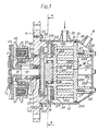
- Fig. 1 shows a vertical sectional view of a compressor unit of the scroll-type according to an embodiment of this invention;
- Fig. 1a is a sectional view of a modification of the embodiment;
- Fig. 2 is a perspective view of the fixed scroll member in the embodiment of Fig. 1;
- Fig. 3 is an exploded perspective view of the driving mechanism in the embodiment of Fig. 1;
- Fig. 4 is an explanatory diagram of the motion of the eccentrical bushing in the embodiment of Fig. 1;
- Fig. 5 is a perspective view of a rotation preventing mechanism in the embodiment of Fig. 1; and
- Fig. 6 is a diagrammatic sectional view illustrating the spiral elements of the fixed and orbiting scroll members.
- Referring to Fig. 1, a fluid displacement apparatus in accordance with the present invention, in particular a
refrigerant compressor unit 1 of an embodiment of the present invention is shown. Theunit 1 includes acompressor housing 10 comprising afront end plate 11 which is, for example, formed of aluminium or aluminium alloy, and a cup-shaped portion 12 which is formed of a press worked steel plate or aluminium die castings. Cup-shaped portion 12 is disposed to one side surface offront end plate 11. Anopening 111 is formed in center offront end plate 11 for penetration of adrive shaft 13. Anannular projection 112 is formed in rear end surface offront end plate 11 which faces cup-shaped portion 12, and projects concentric withopening 111. Cup-shaped portion 12 has aflange portion 121 which extends radially outward along an opening portion thereof.Annular projection 112 is fitted into the opening portion of cup-shaped portion 12. The end surface offlange portion 121 is in contact with the rear end surface offront end plate 11 and is fixed tofront end plate 11 by a fastening means, for example, bolts-nuts. In this embodiment, as shown in Fig. 1, bolt means 113 is screwed into tapped holes formed in the end surface offront end plate 11 throughflange portion 121 of cup-shaped portion 12. Therefore, the opening portion of cup-shaped portion 12 is covered byfront end plate 11. An O-ring member 14 is placed betweenfront end plate 11 andflange portion 121 of cup-shaped portion 12, to thereby secure a seal between the fitting or mating surfaces of theend plate 11 and to cup-shaped portion 12. Alternatively, bolt means 113 may be screwed into tapped holes formed in the end surface of cup-shaped portion 12 throughfront end plate 11 to connect front end plate and cup-shaped portion 12, as shown in Fig. 1a. - Referring to Fig. 1a, cup-
shaped portion 12 is formed thick at angularly-spaced portions of its open end wall, as shown at 122. A tappedhole 123 is axially formed in eachthick portion 122. Abolt 113 is screwed into each tappedhole 123 throughfront end plate 11 to fixedly connectfront end plate 11 and cup-shaped portion 12. Anannular shim 114 is interposed betweenfront end plate 11 and cup-shaped portion 12 to adjust the axial space of the interior ofhousing 10. 0-ring 14 is disposed between the outer surface ofannular projection 112 and the inner surface of cup-shaped portion 12. -
Front end plate 11 has anannular sleeve portion 17 projecting from the front end surface thereof for surroundingdrive shaft 13. In this embodiment as shown in Fig. 1,sleeve portion 17 is formed of steel and is separate fromfront end plate 11. Therefore,sleeve portion 17 is fixed to the front end surface offront end plate 11 byscrews 18, one of which is shown in Fig. 1. Alternatively, thesleeve portion 17 may be formed integral withfront end plate 11. -
Drive shaft 13 is rotatably supported bysleeve portion 17 through a bearing means 19 disposed within the front end portion ofsleeve portion 17.Drive shaft 13 is formed with adisk rotor 15 at its inner end portion, anddisk portion 15 is rotatably supported byfront end plate 11 through a bearing means 16 disposed within an inner peripheral surface ofannular projection 112. Therefore, driveshaft 13 is rotatably supported by the two bearing means 16, 19. Ashaft seal assembly 20 is assembled ondrive shaft 13 within opening 111 offront end plate 11. - A
pulley 22 is rotatably supported by a bearing means 21 which is disposed on outer surface ofsleeve portion 17. An electromagneticannular coil 23 is fixed to the outer surface ofsleeve portion 17 by asupport plate 159 and is received in anannular cavity 160 ofpulley 22. Anarmature plate 24 is elastically supported on the outer end ofdrive shaft 13 which extends fromsleeve portion 17. A magneticclutch comprising pulley 22,magnetic coil 23 andarmature plate 24 is thereby formed. Thus, driveshaft 13 is driven by an external drive power source, for example, a motor of a vehicle, through a rotation force transmitting means such as the magnetic clutch. A fixedscroll member 25, anorbiting scroll member 26, a driving mechanism of orbitingscroll member 26 and a rotation preventing/thrust bearing means of orbitingscroll member 26 are disposed in an inner chamber of cup shapedportion 12. The inner chamber is formed between inner wall of cup shapedportion 12 andfront end plate 11. -
Fixed scroll member 25 includes acircular end plate 251 and a wrap means orspiral elements 252 affixed to or extending from one major side surface ofcircular plate 251.Circular plate 251 of fixedscroll member 25 is formed with a plurality oflegs 253 axially projecting from a major end surface opposite to the side of theplate 251 from which spiralelement 252 extend or are affixed. In the embodiment of this invention as shown in Fig. 2, awall portion 257 is formed in the area between of eachleg 253 for reinforcement oflegs 253. An end surface of eachleg 253 is fitted against the inner surface of abottom plate portion 124 of cup shapedportion 12 and fixed tobottom plate portion 124 of cup shapedportion 12 byscrews 27 which screw intolegs 253 from the outside ofbottom plate portion 124. -
Legs 253 may be formed on notcircular plate 251 but the bottom surface of cup-shapedportion 12. In the arrangement, screws 27 are screwed intocircular plate 251 through the legs. - In another modification, a cylindrical body may be formed on either one of
circular plate 251 and the bottom surface of cup-shapedportion 12 to project towards the other one. A plurality of screw-tapped holes are formed in the projecting end surface of the cylindrical body at its angular spaced position. - A first sealing
member 28 are disposed between the end surface of eachleg 253 and the inner surface ofbottom plate portion 122, to thereby prevent fluid leakage along screws 27. Referring to Fig. 2, anannular groove 255 for receiving sealingmember 28 and a tappedhole 254 for receivingscrew 27 are formed on the end surface of eachleg 253. Agroove 256 is formed on the outer peripheral surface ofcircular plate 251 and a secondseal ring member 29 is disposed therein to form a seal between the inner surface of cup shapedportion 12 and the outer peripheral portion or surface ofcircular plate 251. Thus, the inner chamber of cup shapedportion 12 is partitioned into two chambers bycircular plate 251, such as arear chamber 30 in whichlegs 253 are disposed and afront chamber 31 in which spiralelement 251 of fixedscroll member 25 is disposed. - Cup shaped
portion 12 is provided with afluid inlet port 35 and afluid outlet port 36, which respectively are connected to the front andrear chambers port 258 is formed through thecircular plate 251 at a position near to the center ofspiral element 252 and is connected to the fluid pocket of the spiral element center andrear chamber 30. - Orbiting
scroll member 26 is disposed infront chamber 31. Orbitingscroll member 26 also comprises acircular end plate 261 and a wrap means orspiral element 262 affixed to or extending from one side surface ofcircular end plate 261.Spiral element 262 andspiral element 252 of fixedscroll member 25 interfit at angular offset of 180° and a predetermined radial offset. A pair of fluid pockets are thereby defined betweenspiral elements scroll member 26 is connected to the drive mechanism and to the rotation preventing/thrust bearing mechanism. These last two mechanisms effect orbital motion of theorbiting scroll member 26 at a circular radius Ro by rotation ofdrive shaft 13, to thereby compress fluid passing through the compressor unit. - Generally, radius Ro of orbital motion given by

- As seen in Fig. 6, the pitch (P) of the spiral elements can be defined by 2nrg, where rg is the involute generating circle radius. The radius of orbital motion Ro is also illustrated in Fig. 6 as a locus of an arbitrary point Q on orbiting
scroll member 26. Thespiral element 262 is placed radially offset fromspiral element 252 of fixedscroll member 25 by the distance Ro. Thereby, orbitingscroll member 26 is allowed to undergo the orbital motion of a radius Ro by the rotation ofdrive shaft 13. As the orbiting scroll memebr 26 orbits, line contact between bothspiral elements spiral elements Fluid inlet port 35 which is formed in cup shapedportion 12 is connected to thefront chamber 31 andfluid outlet port 36 which is formed on cup shapedportion 12 is connected to rearchamber 30. Therefore, fluid, or refrigerant gas, introduced intofront chamber 31 from an external fluid circuit throughinlet port 35, is taken into fluid pockets formed between bothspiral elements scroll member 26 orbits, fluid in the fluid pockets is compressed and the compressed fluid is discharged intorear chamber 30 from the fluid pocket of the spiral element center throughhole 258, and therefrom, discharged through anoutlet port 36 to the external fluid circuit, for example, a cooling circuit. - Referring to Figs. 1 and 3, the driving mechanism of orbiting
scroll member 26 will be described. Driveshaft 13, which is rotatably supported bysleeve portion 17 through bearing means, such asball bearing 19, is formed with adisk rotor 15.Disk rotor 15 is rotatably supported byfront end plate 11 through bearing means, such asball bearing 16 disposed in the inner peripheral surface ofannular projection 112. - A crank pin or drive
pin 151 projects axially from an end surface ofdisk rotor 15 and, hence, from an end ofdrive shaft 13, and is radially offset from the center ofdrive shaft 13.Circular plate 261 of orbitingscroll member 26 is provided with atubular boss 263 axially projecting from an end surface opposite to the side thereof from which spiralelement 262 extends or is affixed. A discoid or shortaxial bushing 33 is fitted intoboss 263, and is rotatably supported therein by bearing means, such as aneedle bearing 34.Bushing 33 has abalance weight 331 which is shaped as a portion of a disk or ring and extends radially from bushing 33 along a front surface thereof. Aneccentric hole 332 is formed inbushing 33 radially offset from center ofbushing 33.Drive pin 151 is fitted into the eccentricallydisposed hole 332 within which abearing 32 may be applied.Bushing 33 is therefore driven by the revolution ofdrive pin 151 and permitted to rotate byneedle bearing 34. - Respective placement of center Os of
drive shaft 13, center Oc ofbushing 33, and center Od ofhole 332 and thus ofdrive pin 151, is shown in Fig. 4. In the position shown in Fig. 4, the distance between Os and Oc is the radius Ro of orbital motion, and whendrive pin 151 is placed ineccentric hole 332, center Od ofdrive pin 151 is placed, with respect to Os, on the opposite side of a line L1, which is through Oc and perpendicular to a line L2 through Oc and Os, and also beyond the line through Oc and Os in direction of rotation A ofdrive shaft 13. - In this construction of a driving mechanism, center Oc of
bushing 33 is permitted to swing about the center Od ofdrive pin 151 at a radius E2, as shown in Fig. 4. Such swing motion of center Oc is illustrated as arc Oc'-Oc" in Fig. 4. This permitted swing motion allows theorbiting scroll member 30 to compensate its motion for changes in Ro due to wear on thespiral elements drive shaft 13 rotates, a drive force is exerted at center Od to the left, and a reaction force of gas compression appears at center Oc to the right, both forced being parallel to line L1. Therefore, the arm Od-Oc swing outwardly by creation of the moment generated by the two forces.Spiral element 262 of orbitingscroll member 26 is thereby forced towardspiral element 252 of fixedscroll member 25 and the center of orbitingscroll member 26 orbits with the radius Ro around center Os ofdrive shaft 13. The rotation of orbitingscroll member 26 is prevented by a rotation preventing/thrust bearing mechanism, described more fully hereinafter, whereby orbitingscroll member 26 only orbits while maintaining its angular orientation. The fluid pockets move because of the orbital motion of orbitingscroll member 26, to thereby compress the fluid. - Referring to Fig. 5 and Fig. 1, a rotation preventing/thrust bearing, means 37 will be described. Rotation preventing/thrust bearing means 37 is disposed to surround
boss 263 and is comprised of a fixedring 371 and a slidingring 372.Fixed ring 371 is secured to an end surface ofannular projection 112 offront end plate 11 bypin 373, one of which is shown in Fig. 1.Fixed ring 371 is provided with a pair ofkeyways 371a and 371 b in an axial end surface facing orbitingscroll member 26. Slidingring 372 is disposed in a hollow space between fixedring 371 andcircular plate 261 of orbitingscroll member 26. Slidingring 372 is provided with a pair ofkeys 372a and 372b on the surface facing fixedring 371, which are received inkeyways 371a a and 371b. Therefore, slidingring 372 is slidable in the radial direction by the guide ofkeys 372a and 372b withinkeyways 371 a and 371 b. Slidingring 372 is also provided with a pair ofkeys 372c and 372d on its opposite surface.Keys 372c and 372d are arranged along a diameter perpendicular to the diameter along whichkeys 372a and 372b are arranged.Circular plate 261 of orbitingscroll member 26 is provided with a pair of keyways (in Fig. 5 only one of keyway 261 a is shown, the other keyway is disposed diametrical opposite to keyway 261 a) on a surface facing sliding ring 272 in which are receivedkeys 372c and 372d. Therefore, orbitingscroll member 26 is slidable in a radial direction by guide ofkeys 372c and 372d within the keyways ofcircular plate 261. - Accordingly, orbiting
scroll member 26 is slidable in one radial direction with slidingring 372, and is slidable in another radial direction independently. The second sliding direction is perpendicular to the first radial direction. Therefore, orbitingscroll member 26 is prevented from rotating, but is permitted to move in two radial directions perpendicular to one another. - In addition, sliding
ring 372 is provided with a plurality of pockets or holes 38 which are formed in an axial direction. A bearing means, such asballs 39, each having a diameter which is larger than the thickness of slidingring 372, are retained inpockets 38.Balls 39 contact and roll on the surfaces of fixedring 371 andcircular plate 261. Therefore, the thrust load from orbitingscroll member 26 is supported on fixedring 371 throughballs 39.
Claims (17)
Applications Claiming Priority (2)
| Application Number | Priority Date | Filing Date | Title |
|---|---|---|---|
| JP55059461A JPS5855359B2 (en) | 1980-05-07 | 1980-05-07 | Scroll compressor |
| JP59461/80 | 1980-05-07 |
Publications (2)
| Publication Number | Publication Date |
|---|---|
| EP0039623A1 EP0039623A1 (en) | 1981-11-11 |
| EP0039623B1 true EP0039623B1 (en) | 1985-10-23 |
Family
ID=13113965
Family Applications (1)
| Application Number | Title | Priority Date | Filing Date |
|---|---|---|---|
| EP81302013A Expired EP0039623B1 (en) | 1980-05-07 | 1981-05-07 | Improvements in or relating to scroll-type fluid displacement apparatus |
Country Status (8)
| Country | Link |
|---|---|
| US (1) | US4411604A (en) |
| EP (1) | EP0039623B1 (en) |
| JP (1) | JPS5855359B2 (en) |
| AU (1) | AU546178B2 (en) |
| CA (1) | CA1222985A (en) |
| DE (1) | DE3172693D1 (en) |
| MY (1) | MY8700532A (en) |
| SG (1) | SG26387G (en) |
Families Citing this family (17)
| Publication number | Priority date | Publication date | Assignee | Title |
|---|---|---|---|---|
| JPS5915691A (en) * | 1982-07-15 | 1984-01-26 | Sanden Corp | Scroll type fluid machine |
| JPS59105087U (en) * | 1982-12-30 | 1984-07-14 | 三菱重工業株式会社 | Scroll type fluid machine |
| JPS59121487U (en) * | 1983-02-04 | 1984-08-16 | 三菱重工業株式会社 | Scroll type fluid machine |
| JPS59142480U (en) * | 1983-03-15 | 1984-09-22 | サンデン株式会社 | Scroll type fluid device |
| JPS59142485U (en) * | 1983-03-15 | 1984-09-22 | サンデン株式会社 | Scroll compressor |
| JPH0212316Y2 (en) * | 1985-10-11 | 1990-04-06 | ||
| US4911620A (en) * | 1988-05-12 | 1990-03-27 | Tecumseh Products Company | Scroll compressor top cover plate |
| JPH0219677A (en) * | 1988-07-08 | 1990-01-23 | Sanden Corp | Scroll type fluid compressor |
| JP2541748B2 (en) * | 1993-04-02 | 1996-10-09 | サンデン株式会社 | Scroll type compressor |
| JPH07133768A (en) * | 1993-11-10 | 1995-05-23 | Toyota Autom Loom Works Ltd | Scroll compressor |
| JPH08159056A (en) * | 1994-11-30 | 1996-06-18 | Matsushita Electric Ind Co Ltd | Scroll compressor |
| JPH08151983A (en) * | 1994-11-30 | 1996-06-11 | Matsushita Electric Ind Co Ltd | Scroll compressor |
| JPH10205467A (en) * | 1997-01-27 | 1998-08-04 | Sanden Corp | Scroll compressor |
| JP2000110743A (en) * | 1998-10-01 | 2000-04-18 | Sanden Corp | Scroll type fluid machine |
| JP2000108648A (en) * | 1998-10-05 | 2000-04-18 | Matsushita Electric Ind Co Ltd | Scroll compressor sealing method |
| US8147230B2 (en) * | 2009-04-06 | 2012-04-03 | Chu Henry C | Scroll compressor having rearwardly directed fluid inlet and outlet |
| DE102015101443B3 (en) * | 2015-02-02 | 2016-05-12 | Leistritz Pumpen Gmbh | Fuel pump |
Citations (1)
| Publication number | Priority date | Publication date | Assignee | Title |
|---|---|---|---|---|
| EP0009350A1 (en) * | 1978-09-04 | 1980-04-02 | Sanden Corporation | Scroll-type fluid compressor units |
Family Cites Families (9)
| Publication number | Priority date | Publication date | Assignee | Title |
|---|---|---|---|---|
| US2306632A (en) * | 1940-09-28 | 1942-12-29 | Gen Motors Corp | Refrigerating apparatus |
| US3200752A (en) * | 1963-05-16 | 1965-08-17 | Thompson Ramo Wooldridge Inc | Stack-up slipper pump with integral flow control valve |
| US3402891A (en) * | 1965-08-20 | 1968-09-24 | Trw Inc | Furnace pump and oil burner circuit |
| US3359913A (en) * | 1965-10-22 | 1967-12-26 | Chrysler Corp | Hydraulic pump |
| US3515167A (en) * | 1968-08-22 | 1970-06-02 | Ernest J Svenson | Hydraulic and electrical power unit |
| US3924977A (en) * | 1973-06-11 | 1975-12-09 | Little Inc A | Positive fluid displacement apparatus |
| US3994635A (en) * | 1975-04-21 | 1976-11-30 | Arthur D. Little, Inc. | Scroll member and scroll-type apparatus incorporating the same |
| US4082484A (en) * | 1977-01-24 | 1978-04-04 | Arthur D. Little, Inc. | Scroll-type apparatus with fixed throw crank drive mechanism |
| DE2966200D1 (en) * | 1978-10-30 | 1983-10-27 | Sanden Corp | Scroll-type fluid compressor units |
-
1980
- 1980-05-07 JP JP55059461A patent/JPS5855359B2/en not_active Expired
-
1981
- 1981-05-05 US US06/260,826 patent/US4411604A/en not_active Expired - Lifetime
- 1981-05-06 AU AU70196/81A patent/AU546178B2/en not_active Expired
- 1981-05-07 CA CA000377086A patent/CA1222985A/en not_active Expired
- 1981-05-07 EP EP81302013A patent/EP0039623B1/en not_active Expired
- 1981-05-07 DE DE8181302013T patent/DE3172693D1/en not_active Expired
-
1987
- 1987-03-13 SG SG263/87A patent/SG26387G/en unknown
- 1987-12-30 MY MY532/87A patent/MY8700532A/en unknown
Patent Citations (1)
| Publication number | Priority date | Publication date | Assignee | Title |
|---|---|---|---|---|
| EP0009350A1 (en) * | 1978-09-04 | 1980-04-02 | Sanden Corporation | Scroll-type fluid compressor units |
Also Published As
| Publication number | Publication date |
|---|---|
| MY8700532A (en) | 1987-12-31 |
| JPS5855359B2 (en) | 1983-12-09 |
| US4411604A (en) | 1983-10-25 |
| CA1222985A (en) | 1987-06-16 |
| DE3172693D1 (en) | 1985-11-28 |
| JPS56156492A (en) | 1981-12-03 |
| AU546178B2 (en) | 1985-08-22 |
| SG26387G (en) | 1987-07-10 |
| EP0039623A1 (en) | 1981-11-11 |
| AU7019681A (en) | 1981-11-12 |
Similar Documents
| Publication | Publication Date | Title |
|---|---|---|
| EP0078148B1 (en) | Biased drive mechanism for an orbiting fluid displacement member | |
| EP0037658B1 (en) | Balancing means for a scroll-type fluid displacement apparatus | |
| US4990071A (en) | Scroll type fluid apparatus having two orbiting end plates linked together | |
| CA1311454C (en) | Fluid displacement apparatus | |
| EP0061698B1 (en) | Orbiting piston type fluid displacement apparatus with a rotation preventing device | |
| EP0037728B1 (en) | Improvements in scroll-type fluid compressors | |
| EP0039623A1 (en) | Improvements in or relating to scroll-type fluid displacement apparatus | |
| EP0060495B1 (en) | An improved rotation preventing device for an orbiting piston type fluid apparatus | |
| US4597724A (en) | Scroll type fluid displacement apparatus with centrifugal force balanceweight | |
| EP0227249A1 (en) | Axial sealing mechanism for scroll type fluid displacement apparatus | |
| EP0061064B1 (en) | An orbiting piston type fluid displacement apparatus with rotation preventing mechanism | |
| US4552517A (en) | Scroll type fluid displacement apparatus and method of assembly | |
| EP0078128B1 (en) | A drive bearing device for a fluid displacement apparatus | |
| GB2150640A (en) | Rotary positive-displacement fluid-machine | |
| US4548556A (en) | Interfitting mechanism of spiral elements for scroll-type fluid displacement apparatus | |
| US4477239A (en) | Scroll type fluid displacement apparatus with offset wraps for reduced housing diameter | |
| EP0123407B1 (en) | Rotation-preventing device for an orbiting piston-type fluid displacement apparatus | |
| US4435136A (en) | Orbiting piston type fluid displacement apparatus with shaft bearing and seal mechanisms | |
| EP0065261A2 (en) | Axial sealing mechanism for scroll type fluid displacement apparatus | |
| CA1305688C (en) | Scroll type compressor | |
| EP0122068B1 (en) | Interfitting mechanism of spiral elements for scroll type fluid displacement apparatus | |
| GB2142980A (en) | Scroll-type rotary positive-displacement fluid-machine | |
| EP0075053A1 (en) | Wear-resisting means for scroll-type fluid-displacement apparatuses | |
| EP0122066A1 (en) | Scroll type fluid displacement apparatus with axial moving prevent device of bearing for driving mechanism | |
| EP0240739B1 (en) | Scroll type compressor with lubricating system |
Legal Events
| Date | Code | Title | Description |
|---|---|---|---|
| PUAI | Public reference made under article 153(3) epc to a published international application that has entered the european phase |
Free format text: ORIGINAL CODE: 0009012 |
|
| AK | Designated contracting states |
Designated state(s): DE FR GB IT SE |
|
| 17P | Request for examination filed |
Effective date: 19820419 |
|
| RAP1 | Party data changed (applicant data changed or rights of an application transferred) |
Owner name: SANDEN CORPORATION |
|
| ITF | It: translation for a ep patent filed | ||
| GRAA | (expected) grant |
Free format text: ORIGINAL CODE: 0009210 |
|
| AK | Designated contracting states |
Designated state(s): DE FR GB IT SE |
|
| REF | Corresponds to: |
Ref document number: 3172693 Country of ref document: DE Date of ref document: 19851128 |
|
| ET | Fr: translation filed | ||
| PLBE | No opposition filed within time limit |
Free format text: ORIGINAL CODE: 0009261 |
|
| STAA | Information on the status of an ep patent application or granted ep patent |
Free format text: STATUS: NO OPPOSITION FILED WITHIN TIME LIMIT |
|
| 26N | No opposition filed | ||
| ITTA | It: last paid annual fee | ||
| EAL | Se: european patent in force in sweden |
Ref document number: 81302013.8 |
|
| PGFP | Annual fee paid to national office [announced via postgrant information from national office to epo] |
Ref country code: GB Payment date: 20000503 Year of fee payment: 20 |
|
| PGFP | Annual fee paid to national office [announced via postgrant information from national office to epo] |
Ref country code: SE Payment date: 20000504 Year of fee payment: 20 |
|
| PGFP | Annual fee paid to national office [announced via postgrant information from national office to epo] |
Ref country code: DE Payment date: 20000508 Year of fee payment: 20 |
|
| PGFP | Annual fee paid to national office [announced via postgrant information from national office to epo] |
Ref country code: FR Payment date: 20000510 Year of fee payment: 20 |
|
| PG25 | Lapsed in a contracting state [announced via postgrant information from national office to epo] |
Ref country code: GB Free format text: LAPSE BECAUSE OF EXPIRATION OF PROTECTION Effective date: 20010506 |
|
| PG25 | Lapsed in a contracting state [announced via postgrant information from national office to epo] |
Ref country code: SE Free format text: THE PATENT HAS BEEN ANNULLED BY A DECISION OF A NATIONAL AUTHORITY Effective date: 20010530 |
|
| REG | Reference to a national code |
Ref country code: GB Ref legal event code: PE20 Effective date: 20010506 |
|
| EUG | Se: european patent has lapsed |
Ref document number: 81302013.8 |