EP0039187B1 - Liquid level indicator - Google Patents
Liquid level indicator Download PDFInfo
- Publication number
- EP0039187B1 EP0039187B1 EP19810301714 EP81301714A EP0039187B1 EP 0039187 B1 EP0039187 B1 EP 0039187B1 EP 19810301714 EP19810301714 EP 19810301714 EP 81301714 A EP81301714 A EP 81301714A EP 0039187 B1 EP0039187 B1 EP 0039187B1
- Authority
- EP
- European Patent Office
- Prior art keywords
- indicator
- liquid
- prism
- liquid level
- accordance
- Prior art date
- Legal status (The legal status is an assumption and is not a legal conclusion. Google has not performed a legal analysis and makes no representation as to the accuracy of the status listed.)
- Expired
Links
Images
Classifications
-
- G—PHYSICS
- G01—MEASURING; TESTING
- G01F—MEASURING VOLUME, VOLUME FLOW, MASS FLOW OR LIQUID LEVEL; METERING BY VOLUME
- G01F23/00—Indicating or measuring liquid level or level of fluent solid material, e.g. indicating in terms of volume or indicating by means of an alarm
- G01F23/22—Indicating or measuring liquid level or level of fluent solid material, e.g. indicating in terms of volume or indicating by means of an alarm by measuring physical variables, other than linear dimensions, pressure or weight, dependent on the level to be measured, e.g. by difference of heat transfer of steam or water
- G01F23/28—Indicating or measuring liquid level or level of fluent solid material, e.g. indicating in terms of volume or indicating by means of an alarm by measuring physical variables, other than linear dimensions, pressure or weight, dependent on the level to be measured, e.g. by difference of heat transfer of steam or water by measuring the variations of parameters of electromagnetic or acoustic waves applied directly to the liquid or fluent solid material
- G01F23/284—Electromagnetic waves
- G01F23/292—Light, e.g. infrared or ultraviolet
- G01F23/2921—Light, e.g. infrared or ultraviolet for discrete levels
- G01F23/2922—Light, e.g. infrared or ultraviolet for discrete levels with light-conducting sensing elements, e.g. prisms
Definitions
- This invention relates to liquid level indicators. More particularly, the present invention relates to an improved liquid level indicator which is particularly useful for indicating or signaling that coloured, viscous liquids contained within a reservoir have been depleted.
- One-piece, light transmissive liquid level indicators have been used to detect the level of liquids contained in many varieties of reservoirs. Perhaps the most widely known usage of such indicators (or "eyes" as they are sometimes called) is in the area of detection of the level of electrolyte within an automobile battery.
- a number of U.S. Patents e.g., 1,883,971, 3,363,224, 3,383,917, 3,442,127 and 3,535,934, describe indicators which can be used in auto batteries (as well as other applications) to detect the level of colourless, non-viscous battery electrolyte without having to remove a cover from one of the battery cells.
- Other contexts in which such eye-type indicators have been used include automobile radiators or in dishwashing machines to detect the level of liquid compositions which are dispensed during the dishwashing cycle.
- U.S. Patent 3,442,127 discloses a liquid level indicator which has superficial similarities to the present invention, for example the present invention and U.S. Patent No. 3,442,127 both illustrate a liquid level indicator with a domed head.
- U.S. No. 3,442, 127 does not disclose a red indicator for use in a liquid having a second colour, for example blue. It teaches that the stem reflector which is a coating of semi-transparent lacquer could be an illuminating bright red colour but it does not teach that the monitored liquid should be a second colour so that an interaction between the colours would create an "substantially black" image when the pointed end indicator is inserted into the liquid.
- U.S. Patent No. 3,535,934 describes a liquid level indicator comprising an elongate member of light transmitting material, but does not teach a liquid level indicator having a large rh/rs ratio which also includes a colour having a particular interactive effect with the liquid being monitored. Likewise, U.K. Patent No. 996,822 does not teach the interactive colour effect discussed above.
- the present invention is distinguished from the above mentioned patents in that none of these references show a large lens-like head in combination with a prismatic end in further combination with a probe having a particular colour in relation to the colour of the liquid to be monitored.
- the present invention substantially reduces the problems encountered with conventional liquid level indicators.
- the present invention provides a liquid level indicator (8) comprising a substantially spherical lens-like transparent head (10) having a generally convex exterior surface (11) and having a base radius of rh, an elongate, transparent stem (20) extending from the head (10) having a substantially circular cross-section and having a radius of r s , the stem having reflecting means (22) on its distal end, rh being at least 50% greater than rg, characterised in that the reflecting means (22) is a pointed prism (23, 25) said prism being internally reflecting in air and in that the indicator is of a first colour such that when the prism is immersed in a liquid of a second colour, the indicator appears substantially black.
- the present invention also forms part of a liquid level monitoring assembly, said liquid level indicator (8) being vertically disposed in a reservoir adapted to receive a liquid and said liquid level indicator (8), said indicator (8) appearing substantially said first colour when the prism (23, 25) is disposed above the surface of the liquid.
- liquid level indicator 8 comprising a lens-like transparent head 10 and an elongated, transparent stem 20.
- indicator 8 is depicted with a cooperating support means therefor.
- the support means is generally a cylindrical, slightly tapered collar 12 having disposed therein an interior, essentially flat radial flange 14 which can be permanently affixed to the indicator 8 and which serves to support it vertically.
- Protruding radially from collar 12 are a plurality of exterior projections 16 which are primarily decorative but which tend to improve the ease with which the collar may be hand turned.
- Interior threads (not shown but the location thereof being indicated by arrow 13) may be molded or machined into collar 12 beneath flange 14.
- Such internally disposed, female threads on the collar will cooperate with exterior, male threads on a neck portion of a reservoir containing a liquid whose level is to be monitored.
- the threads on the collar will screw onto the threads on the neck portion of the liquid reservoir, thus permitting the indicator-collar assembly to be securely threaded into place.
- the indicator depicted in Figures 1 and 2 is particularly adapted to detect the level of liquid in a reservoir of a dishwashing machine.
- a reservoir may contain, for example, a liquid additive which would be dispensed during the dishwashing cycle and would be located in the door of the dishmachine.
- Stem 20 is essentially circular in cross-section throughout much of its length thus making its surface 21 cylindrical.
- prism 22 is conical in configuration and comes to a point 25.
- the distal end of stem 20 i.e., the prism end
- the conical prism depicted is produced essentially by forming the end of the stem into a fairly pointed cone.
- the prism or prism section is created by the configuration of the distal end of the stem, there being no external coatings or reflectors thereon.
- internal reflecting it is meant that light entering head 10 which is transmitted through head 10 into stem 20 will be essentially totally internally reflected at the surface 23 of prism 22 (when the prism is not immersed in the liquid). After being reflected from surface 23 (opposing portions of which are preferably disposed at about a 45 degree angle), the light will return to head 10 where it will emerge and be observed.
- prism 22 is pointed, i.e., to come to an apex such as that of a cone or pyramid.
- an indicator having prism section or portion which is not pointed tends to retain more of the liquid on the prism, i.e. distal, end of the indicator. This tends to permit more light to exit from the indicator into the retained liquid and thereby lessens the intensity of reflected light seen from the head.
- a pointed indicator tends to cause retained liquid to be collected at its point (by gravitational flow) in a droplet which then tends to fall into the reservoir therebelow.
- a pointed prism tends to reflect (internally) incident light more efficiently (than a rounded prism), thereby also increasing .the brightness of the indicator when the reservoir is depleted.
- Figure 3 is a view of the invention of Figures 1 and 2 omitting collar 12.
- the exterior surface 11 of head 10 is generally convex, and that head 10 has a planar base 15 which can permit stem 20 to be light transmissively bonded to it (the indicator may also be formed in one piece).
- stem 20 is light transmissively affixed to head 10 so that light entering head 10 (represented by arrows 28) will be transmitted thereto.
- the relationship between the radius of the stem r and the radius of the base of the head r h provides a ridge or circular ring 24 which can be permanently mounted (e.g., by means of an adhesive) on an internal flange (e.g., flange 14) of a cooperating support means.
- the lens-like head of the present invention increases the radial distance from the axis of the indicator (line 3-3) from which the indicator may be observed. This occurs because the lens-like head gathers (and emits) more light than conventional indicators.
- the lens-like head of the present invention permits the indicator to be read from positions which are further radially disposed from the axis of the indicator.
- the . material of the indicator 8 has an index of refraction such that a substantial portion of those light rays from the sun or any artificial source which strike the head end surface 11 from above and from the side of the device are refracted and directed downwardly along the length of the stem 20.
- light rays passing into the device travel until they meet an exterior surface of the device (e.g., 23). If the exterior surface is exposed to the air, the ray is reflected back into the device.
- the function is such that a major portion of the light rays entering head 10 are directed along the length of the device to the reflecting surface 23 of the prism 22. If the reflecting surface 23 is exposed to the air, the light rays are reflected back toward head 10 along paths of travel such that they strike the head exterior surface 11 and pass out from the upper end of the indicator 8 and may be observed. If, on the other hand, the reflecting surface 23 is immersed in a liquid, most of the light rays pass through the surface 23 and into the liquid of the reservoir.
- the radius of the base of the head (r h ) must be greater than the radius of stem 20 (rs).
- rh should be at least 50 percent greater than r s (i.e., the ratio rh;rs is at least 1.5:1). More preferably, rh should be 100% greater than r. (i.e., the ratio rh to rsshould be 2:1 or greater).
- r h is seen to be equal to the radius of a circle defined by the intersection of a plane and a sphere of which head 10 may be a portion. The base radius of the head generally is measured in the plane wherein the head and stem intersect.
- the radius of the stem (r s ) is defined to be the distance from the axis of the stem (dotted line 30) to its exterior surface 21.
- Figures 5 and 6 depict r h and r s for two different indicators. It should be understood that r h is not equal to the radius of a sphere from which head 10 may be a portion, since, in both Figures 5 and 6, head 10 may have been sliced from the same sphere.
- the present indicator is particularly useful in a dishwashing machine.
- Most domestic dishwashing machines sold today are equipped with a rinse aid dispenser (and thus a supply of rinse additive) which typically adds 0.5 to 1.0 ml of a special low foaming wetting agent to the rinse cycle of the machine.
- the rinse additive provides "sheeting" of water and minimizes filming and spotting of glasses, dishes and flatware. Another benefit of the wetting agent is the shortening of the drying time of the dishes.
- the present invention derives from the concern that not only must the liquid level indicator be reliable but it must also carry a message of sufficient intensity and meaning for it to prompt the operator to refill the rinse additive dispenser whenever its supply of rinse additive is depleted.
- the light intensity from the present liquid level indicator device appears to be especially intense even in moderately lit environments such as in a kitchen under artifical lighting conditions.
- the present indicator be of a first color and the liquid (whose level is to be detected) should be of a second color such that, when the prism end of the indicator is immersed in the liquid, the indicator will be essentially dark or black.
- the indicator should be red or pink and the liquid whose level is to be detected should be blue or purple.
- the indicator will appear to be red when the liquid is depleted and itwill appear to be black when sufficient liquid is contained within the reservoir. It is felt that the pink-black distinction between unfilled and filled will more clearly and unambiguously indicate to an observer that an action (i.e., filling of the reservoir) should be taken.
- Indicators of the present invention may be manufactured from any suitable material which is light-transmissive and which can be suitably colored.
- acrylic resins, styrene, copolymers, polyolefinic resins with suitable color-absorbing materials therein are employed to make the present indicator.
- Particularly desirable are those materials which are light transmissive (i.e., transparent) and which exhibit minimal scatter of light transmitted therethrough.
- Such materials and suitable colorants will be well known to one skilled in the art of polymer fabrication. Colorants which may be used to impart a desired hue to the present indicators if manufactured from plastics are listed in e.g., "Modern Plastics Encyclopedia" 1978-79 edition, pp. 660 to 672.
- the material of which the indicator is made has to be resistant to acid and basic chemical attack.
- Rinse additives such as the rinse additive commercially available from Economics Laboratory, Inc. under the trade designation "Jet Dry" are normally neutral in pH but the dishwashing detergents are moderately alkaline and therefore require .
- an indicator material that is resistant to surfactants as well as alkaline chemical attack will necessarily need to be thermally stable at the highest water temperature to which they are exposed.
- a particularly preferred resin from which the present indicators may be manufactured is believed to be a copolymer of styrene and methylmethacrylate and is sold under the designation "NAS" by the Richardson Company.
Landscapes
- Physics & Mathematics (AREA)
- Electromagnetism (AREA)
- Thermal Sciences (AREA)
- Fluid Mechanics (AREA)
- General Physics & Mathematics (AREA)
- Measurement Of Levels Of Liquids Or Fluent Solid Materials (AREA)
Description
- This invention relates to liquid level indicators. More particularly, the present invention relates to an improved liquid level indicator which is particularly useful for indicating or signaling that coloured, viscous liquids contained within a reservoir have been depleted.
- One-piece, light transmissive liquid level indicators have been used to detect the level of liquids contained in many varieties of reservoirs. Perhaps the most widely known usage of such indicators (or "eyes" as they are sometimes called) is in the area of detection of the level of electrolyte within an automobile battery. A number of U.S. Patents, e.g., 1,883,971, 3,363,224, 3,383,917, 3,442,127 and 3,535,934, describe indicators which can be used in auto batteries (as well as other applications) to detect the level of colourless, non-viscous battery electrolyte without having to remove a cover from one of the battery cells. Other contexts in which such eye-type indicators have been used include automobile radiators or in dishwashing machines to detect the level of liquid compositions which are dispensed during the dishwashing cycle.
- U.S. Patent 3,442,127 discloses a liquid level indicator which has superficial similarities to the present invention, for example the present invention and U.S. Patent No. 3,442,127 both illustrate a liquid level indicator with a domed head. U.S. No. 3,442, 127 does not disclose a red indicator for use in a liquid having a second colour, for example blue. It teaches that the stem reflector which is a coating of semi-transparent lacquer could be an illuminating bright red colour but it does not teach that the monitored liquid should be a second colour so that an interaction between the colours would create an "substantially black" image when the pointed end indicator is inserted into the liquid.
- U.S. Patent No. 3,535,934 describes a liquid level indicator comprising an elongate member of light transmitting material, but does not teach a liquid level indicator having a large rh/rs ratio which also includes a colour having a particular interactive effect with the liquid being monitored. Likewise, U.K. Patent No. 996,822 does not teach the interactive colour effect discussed above.
- The present invention is distinguished from the above mentioned patents in that none of these references show a large lens-like head in combination with a prismatic end in further combination with a probe having a particular colour in relation to the colour of the liquid to be monitored.
- Two problems have been encountered with conventional eye-type liquid level indicators. First, such indicators generally are not easily readable unless observed from a position very near to the their longitudinal axis. The problem of how to increase the radial distance away from the indicator axis from which the indicator may be read has been recognized in the patent literature (e.g. US-A-3,362,224).
- Second, problems have often been encountered in determining whether the "eye" shows that the liquid level is or is not at a sufficient level. In such eye-type indicators there are generally two modes. The eye either appears brightly lit or very dimly lit depending upon whether the distal end of the eye is submerged in the liquid or is above it. Experience has taught that these two modes are visually sufficient for detecting the sufficient-depleted state of the reservoir but the connotation of what these two modes signify is confusing or lacking. In other words, the consumer has to decide whether the reservoir is empty when the eye is bright or when it is dim. This ambiguity of conventional liquid level indicators tends to confuse the observer. Since the observer checking a liquid level in a reservoir usually wants to be sure that the liquid therein is at the appropriate level, the liquid level is checked by some other means such as by removing a separate cap or cover. This tends to reduce the perceived utility of the indicator.
- The present invention substantially reduces the problems encountered with conventional liquid level indicators.
- Accordingly, the present invention provides a liquid level indicator (8) comprising a substantially spherical lens-like transparent head (10) having a generally convex exterior surface (11) and having a base radius of rh, an elongate, transparent stem (20) extending from the head (10) having a substantially circular cross-section and having a radius of rs, the stem having reflecting means (22) on its distal end, rh being at least 50% greater than rg, characterised in that the reflecting means (22) is a pointed prism (23, 25) said prism being internally reflecting in air and in that the indicator is of a first colour such that when the prism is immersed in a liquid of a second colour, the indicator appears substantially black.
- The present invention also forms part of a liquid level monitoring assembly, said liquid level indicator (8) being vertically disposed in a reservoir adapted to receive a liquid and said liquid level indicator (8), said indicator (8) appearing substantially said first colour when the prism (23, 25) is disposed above the surface of the liquid.
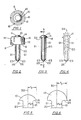
- The invention will now be further described in connection with the accompanying drawings wherein like reference characters refer to the same parts throughout the several views and in which:
- Figure 1 is a top view of an indicator of the present invention showing the indicator with a cooperating support means;
- Figure 2 is a side view of the indicator of Figure 1;
- Figure 3 is a side view of the indicator of Figures 1 and 2 with the support means removed;
- Figure 4 is a cross-sectional view of the indicator of Figure 3 taken along line 3-3, the longitudinal axis of the indicator;
- Figure 5 is a cross-sectional view of the head portion of the indicator of Figure 2 at twice its normal size; and
- Figure 6 is a cross-sectional view of the head portion of a second embodiment of the invention at twice its normal size.
- Thus there is shown in Figures 1 through 6 liquid level indicator 8 comprising a lens-like
transparent head 10 and an elongated,transparent stem 20. In Figures 1 and 2, indicator 8 is depicted with a cooperating support means therefor. In this embodiment of the invention, the support means is generally a cylindrical, slightlytapered collar 12 having disposed therein an interior, essentially flatradial flange 14 which can be permanently affixed to the indicator 8 and which serves to support it vertically. Protruding radially fromcollar 12 are a plurality ofexterior projections 16 which are primarily decorative but which tend to improve the ease with which the collar may be hand turned. Interior threads (not shown but the location thereof being indicated by arrow 13) may be molded or machined intocollar 12 beneathflange 14. Such internally disposed, female threads on the collar will cooperate with exterior, male threads on a neck portion of a reservoir containing a liquid whose level is to be monitored. In this instance, the threads on the collar will screw onto the threads on the neck portion of the liquid reservoir, thus permitting the indicator-collar assembly to be securely threaded into place. The indicator depicted in Figures 1 and 2 is particularly adapted to detect the level of liquid in a reservoir of a dishwashing machine. Such a reservoir may contain, for example, a liquid additive which would be dispensed during the dishwashing cycle and would be located in the door of the dishmachine. - In Figures 2, and 4 the
head 10 and elongated,transparent stem 20 of the present indicator are more clearly shown.Stem 20 is essentially circular in cross-section throughout much of its length thus making itssurface 21 cylindrical. On the end of thestem 20 opposite head 10 (i.e., on the distal end of stem 20) is an internally reflecting, pointed prism or prism section orportion 22. In this preferred embodiment of this invention,prism 22 is conical in configuration and comes to apoint 25. The distal end of stem 20 (i.e., the prism end) may be of internally reflecting configurations such as triangular or square pyramids. The conical prism depicted is produced essentially by forming the end of the stem into a fairly pointed cone. In other words, the prism or prism section is created by the configuration of the distal end of the stem, there being no external coatings or reflectors thereon. By "internally reflecting" it is meant thatlight entering head 10 which is transmitted throughhead 10 intostem 20 will be essentially totally internally reflected at thesurface 23 of prism 22 (when the prism is not immersed in the liquid). After being reflected from surface 23 (opposing portions of which are preferably disposed at about a 45 degree angle), the light will return tohead 10 where it will emerge and be observed. - Particularly when the present invention is intended to detect the level of viscous liquids, it is necessary for
prism 22 to be pointed, i.e., to come to an apex such as that of a cone or pyramid. After being immersed in a viscous liquid, an indicator having prism section or portion which is not pointed (e.g., which is rounded) tends to retain more of the liquid on the prism, i.e. distal, end of the indicator. This tends to permit more light to exit from the indicator into the retained liquid and thereby lessens the intensity of reflected light seen from the head. A pointed indicator tends to cause retained liquid to be collected at its point (by gravitational flow) in a droplet which then tends to fall into the reservoir therebelow. Furthermore, a pointed prism tends to reflect (internally) incident light more efficiently (than a rounded prism), thereby also increasing .the brightness of the indicator when the reservoir is depleted. - Figure 3 is a view of the invention of Figures 1 and 2 omitting
collar 12. In Figure 3 it is seen that the exterior surface 11 ofhead 10 is generally convex, and thathead 10 has aplanar base 15 which can permitstem 20 to be light transmissively bonded to it (the indicator may also be formed in one piece). As shown in Figure 4,stem 20 is light transmissively affixed tohead 10 so that light entering head 10 (represented by arrows 28) will be transmitted thereto. As is more fully described below, the relationship between the radius of the stem r and the radius of the base of the head rh provides a ridge orcircular ring 24 which can be permanently mounted (e.g., by means of an adhesive) on an internal flange (e.g., flange 14) of a cooperating support means. In addition to providing means for supporting the indicator, the lens-like head of the present invention increases the radial distance from the axis of the indicator (line 3-3) from which the indicator may be observed. This occurs because the lens-like head gathers (and emits) more light than conventional indicators. Thus, the lens-like head of the present invention permits the indicator to be read from positions which are further radially disposed from the axis of the indicator. - As will be understood (particularly as described at
columns 3 and 4 of U.S. Patent 3,362,224), the . material of the indicator 8 has an index of refraction such that a substantial portion of those light rays from the sun or any artificial source which strike the head end surface 11 from above and from the side of the device are refracted and directed downwardly along the length of thestem 20. In other words, light rays passing into the device (such as indicated bylight paths 28 of FIG. 4) travel until they meet an exterior surface of the device (e.g., 23). If the exterior surface is exposed to the air, the ray is reflected back into the device. This action holds true as long as there is a substantial angle of incidence between the direction of the light ray and the surface which it strikes and more particularly as long as the angle of incidence is in excess of a known critical angle. In any event, the function is such that a major portion of the lightrays entering head 10 are directed along the length of the device to the reflectingsurface 23 of theprism 22. If the reflectingsurface 23 is exposed to the air, the light rays are reflected back towardhead 10 along paths of travel such that they strike the head exterior surface 11 and pass out from the upper end of the indicator 8 and may be observed. If, on the other hand, the reflectingsurface 23 is immersed in a liquid, most of the light rays pass through thesurface 23 and into the liquid of the reservoir. In other words, most of the light rays are not reflected back toward the head of the device and thus the head appears dark. Thus, it is seen that when the distal prismatic end ofstem 20 is immersed in liquid, the indicator device 8 appears dark and the liquid in the reservoir is at the desired level. When the liquid in the reservoir falls belowprismatic end 22, exterior surface thereof 23 being exposed to the air, the device appears lighted. - As stated above, in the practice of the present invention, the radius of the base of the head (rh) must be greater than the radius of stem 20 (rs). In a preferred sense, rh should be at least 50 percent greater than rs (i.e., the ratio rh;rs is at least 1.5:1). More preferably, rh should be 100% greater than r. (i.e., the ratio rh to rsshould be 2:1 or greater). With reference to Figures 5 and 6, rh is seen to be equal to the radius of a circle defined by the intersection of a plane and a sphere of which head 10 may be a portion. The base radius of the head generally is measured in the plane wherein the head and stem intersect. The radius of the stem (rs) is defined to be the distance from the axis of the stem (dotted line 30) to its
exterior surface 21. Figures 5 and 6 depict rh and rs for two different indicators. It should be understood that rh is not equal to the radius of a sphere from which head 10 may be a portion, since, in both Figures 5 and 6,head 10 may have been sliced from the same sphere. - As noted above, the present indicator is particularly useful in a dishwashing machine. Most domestic dishwashing machines sold today are equipped with a rinse aid dispenser (and thus a supply of rinse additive) which typically adds 0.5 to 1.0 ml of a special low foaming wetting agent to the rinse cycle of the machine. The rinse additive provides "sheeting" of water and minimizes filming and spotting of glasses, dishes and flatware. Another benefit of the wetting agent is the shortening of the drying time of the dishes.
- For various reasons (including signal ambiguity), conventional liquid level indicator devices tend to be overlooked or ignored by the consumer. As a result, many dishwashing machines are operated without sufficient available rinse additive. This tends to reduce the performance of the dishwasher machine producing noticeable spotting and filming of the glassware and flatware. Once the spotting and filming on the dishes have built up to a noticeable and objectionable level, it may be necessary to clean the dishes with a special product (including an acidic product) to restore them to an acceptable condition. Additional treatment of spotted dishes with special products is inconvenient, thus making it important that a dependable and eye-catching low liquid level warning device be employed to motivate the consumer to refill the rinse aid dispenser before it is depleted.
- The present invention derives from the concern that not only must the liquid level indicator be reliable but it must also carry a message of sufficient intensity and meaning for it to prompt the operator to refill the rinse additive dispenser whenever its supply of rinse additive is depleted. Surprisingly, the light intensity from the present liquid level indicator device appears to be especially intense even in moderately lit environments such as in a kitchen under artifical lighting conditions.
- As noted above, it is important that the present indicator be of a first color and the liquid (whose level is to be detected) should be of a second color such that, when the prism end of the indicator is immersed in the liquid, the indicator will be essentially dark or black. When the liquid has been depleted below its desired level, light passing through the indicator will appear to be the first color. In a particularly preferred embodiment of the present invention, the indicator should be red or pink and the liquid whose level is to be detected should be blue or purple. In this embodiment the indicator will appear to be red when the liquid is depleted and itwill appear to be black when sufficient liquid is contained within the reservoir. It is felt that the pink-black distinction between unfilled and filled will more clearly and unambiguously indicate to an observer that an action (i.e., filling of the reservoir) should be taken.
- Indicators of the present invention may be manufactured from any suitable material which is light-transmissive and which can be suitably colored. Thus, acrylic resins, styrene, copolymers, polyolefinic resins with suitable color-absorbing materials therein are employed to make the present indicator. Particularly desirable are those materials which are light transmissive (i.e., transparent) and which exhibit minimal scatter of light transmitted therethrough. Such materials and suitable colorants will be well known to one skilled in the art of polymer fabrication. Colorants which may be used to impart a desired hue to the present indicators if manufactured from plastics are listed in e.g., "Modern Plastics Encyclopedia" 1978-79 edition, pp. 660 to 672.
- In the dishmachine environment in which the present invention is used, in addition to having the necessary optical properties, the material of which the indicator is made has to be resistant to acid and basic chemical attack. Rinse additives (such as the rinse additive commercially available from Economics Laboratory, Inc. under the trade designation "Jet Dry") are normally neutral in pH but the dishwashing detergents are moderately alkaline and therefore require . an indicator material that is resistant to surfactants as well as alkaline chemical attack. Where indicators are to be used in dishmachines, the indicator material (as well as any support means or exposed reservoir portions) will necessarily need to be thermally stable at the highest water temperature to which they are exposed. A particularly preferred resin from which the present indicators may be manufactured (e.g., by injection molding) is believed to be a copolymer of styrene and methylmethacrylate and is sold under the designation "NAS" by the Richardson Company.
- Various modifications and alterations of the invention will become apparent to those skilled in the art without departing from the scope of the claims and it should be understood that this invention is not to be limited to the illustrative embodiments set forth herein.
Claims (11)
Applications Claiming Priority (2)
| Application Number | Priority Date | Filing Date | Title |
|---|---|---|---|
| US14426780A | 1980-04-28 | 1980-04-28 | |
| US144267 | 1980-04-28 |
Publications (2)
| Publication Number | Publication Date |
|---|---|
| EP0039187A1 EP0039187A1 (en) | 1981-11-04 |
| EP0039187B1 true EP0039187B1 (en) | 1985-07-24 |
Family
ID=22507828
Family Applications (1)
| Application Number | Title | Priority Date | Filing Date |
|---|---|---|---|
| EP19810301714 Expired EP0039187B1 (en) | 1980-04-28 | 1981-04-16 | Liquid level indicator |
Country Status (7)
| Country | Link |
|---|---|
| EP (1) | EP0039187B1 (en) |
| JP (1) | JPS5735720A (en) |
| AU (1) | AU6957981A (en) |
| BR (1) | BR8102580A (en) |
| CA (1) | CA1161412A (en) |
| DE (1) | DE3171466D1 (en) |
| NZ (1) | NZ196951A (en) |
Families Citing this family (4)
| Publication number | Priority date | Publication date | Assignee | Title |
|---|---|---|---|---|
| GB2195446B (en) * | 1986-09-26 | 1990-02-28 | Philips Electronic Associated | A liquid level indicator |
| DE4010948A1 (en) * | 1990-04-05 | 1991-10-10 | Fibronix Sensoren Gmbh | DEVICE FOR OPTOELECTRICAL INTERFACE AND REFRESH MEASUREMENT MEASUREMENT IN LIQUIDS |
| DE4010949A1 (en) * | 1990-04-05 | 1991-10-10 | Fibronix Sensoren Gmbh | OPTOELECTRIC LEVEL INDICATOR |
| GB2266955B (en) * | 1992-05-13 | 1995-03-08 | George Devenish | Liquid level indicator |
Family Cites Families (6)
| Publication number | Priority date | Publication date | Assignee | Title |
|---|---|---|---|---|
| GB996822A (en) * | 1960-10-06 | 1965-06-30 | Genevac Ltd | An improved liquid level indicator |
| US3442127A (en) * | 1966-08-29 | 1969-05-06 | Edgar B Nichols | Liquid level indicator |
| US3535934A (en) * | 1969-02-10 | 1970-10-27 | Illinois Tool Works | Liquid level indicator |
| US3570311A (en) * | 1969-03-19 | 1971-03-16 | Illinois Tool Works | Liquid level indicator assembly |
| GB1508576A (en) * | 1974-09-17 | 1978-04-26 | Ici Ltd | Dispersion of solids in organic solvents |
| US4074025A (en) * | 1976-03-29 | 1978-02-14 | Miyagawa Kasei Industry Co., Ltd. | Indicating device for storage battery |
-
1981
- 1981-04-15 AU AU69579/81A patent/AU6957981A/en not_active Abandoned
- 1981-04-16 EP EP19810301714 patent/EP0039187B1/en not_active Expired
- 1981-04-16 DE DE8181301714T patent/DE3171466D1/en not_active Expired
- 1981-04-27 CA CA000376299A patent/CA1161412A/en not_active Expired
- 1981-04-28 JP JP6353381A patent/JPS5735720A/en active Pending
- 1981-04-28 NZ NZ19695181A patent/NZ196951A/en unknown
- 1981-04-28 BR BR8102580A patent/BR8102580A/en unknown
Also Published As
| Publication number | Publication date |
|---|---|
| DE3171466D1 (en) | 1985-08-29 |
| BR8102580A (en) | 1982-01-19 |
| CA1161412A (en) | 1984-01-31 |
| AU6957981A (en) | 1981-11-05 |
| JPS5735720A (en) | 1982-02-26 |
| NZ196951A (en) | 1984-02-03 |
| EP0039187A1 (en) | 1981-11-04 |
Similar Documents
| Publication | Publication Date | Title |
|---|---|---|
| US3995169A (en) | Optical liquid level gauge | |
| US3362224A (en) | Liquid level indicator | |
| US3597973A (en) | Combined level indicator and hydrometer | |
| US3675722A (en) | Pressure indicator | |
| US4979797A (en) | Multi-level fiber-optic liquid-level sensing system | |
| EP0795740A1 (en) | Self testing optical liquid level sensor | |
| CA1332792C (en) | Liquid level gauging apparatus | |
| US3553666A (en) | Remote sensing indicator device | |
| EP0367786A4 (en) | Optical liquid level sensor | |
| JPH06102080A (en) | Liquid level monitor | |
| CA1161412A (en) | Liquid level indicator | |
| US3535934A (en) | Liquid level indicator | |
| EP0347095A1 (en) | Optical liquid-level sensing means | |
| US3568628A (en) | Liquid level indicator | |
| EP0006317A1 (en) | Liquid level detector | |
| US3597972A (en) | Combined level indicator and hydrometer | |
| US20020124643A1 (en) | Flexible optical fiber remote level sensor | |
| US3442127A (en) | Liquid level indicator | |
| US3543581A (en) | Liquid level indicator | |
| GB2195446A (en) | A liquid level indicator | |
| US4787329A (en) | Device for detection of imminent gas depletion of a liquified gas tank and gas lighter equipped with this device | |
| US2627748A (en) | Battery liquid level indicator | |
| US3597971A (en) | Combined level indicator and hydrometer | |
| US7228737B2 (en) | Hydrometer/fluid level sensor | |
| JPS57122320A (en) | Liquid level detector |
Legal Events
| Date | Code | Title | Description |
|---|---|---|---|
| PUAI | Public reference made under article 153(3) epc to a published international application that has entered the european phase |
Free format text: ORIGINAL CODE: 0009012 |
|
| AK | Designated contracting states |
Designated state(s): DE FR GB IT SE |
|
| 17P | Request for examination filed |
Effective date: 19820204 |
|
| ITF | It: translation for a ep patent filed | ||
| GRAA | (expected) grant |
Free format text: ORIGINAL CODE: 0009210 |
|
| AK | Designated contracting states |
Designated state(s): DE FR GB IT SE |
|
| REF | Corresponds to: |
Ref document number: 3171466 Country of ref document: DE Date of ref document: 19850829 |
|
| ET | Fr: translation filed | ||
| PG25 | Lapsed in a contracting state [announced via postgrant information from national office to epo] |
Ref country code: SE Effective date: 19860417 |
|
| PLBE | No opposition filed within time limit |
Free format text: ORIGINAL CODE: 0009261 |
|
| STAA | Information on the status of an ep patent application or granted ep patent |
Free format text: STATUS: NO OPPOSITION FILED WITHIN TIME LIMIT |
|
| 26N | No opposition filed | ||
| GBPC | Gb: european patent ceased through non-payment of renewal fee | ||
| PG25 | Lapsed in a contracting state [announced via postgrant information from national office to epo] |
Ref country code: FR Free format text: LAPSE BECAUSE OF NON-PAYMENT OF DUE FEES Effective date: 19861231 |
|
| PG25 | Lapsed in a contracting state [announced via postgrant information from national office to epo] |
Ref country code: DE Effective date: 19870101 |
|
| REG | Reference to a national code |
Ref country code: FR Ref legal event code: ST |
|
| PG25 | Lapsed in a contracting state [announced via postgrant information from national office to epo] |
Ref country code: GB Effective date: 19881118 |
|
| EUG | Se: european patent has lapsed |
Ref document number: 81301714.2 Effective date: 19870224 |