EP0038675B1 - Electronic musical instrument - Google Patents
Electronic musical instrument Download PDFInfo
- Publication number
- EP0038675B1 EP0038675B1 EP81301665A EP81301665A EP0038675B1 EP 0038675 B1 EP0038675 B1 EP 0038675B1 EP 81301665 A EP81301665 A EP 81301665A EP 81301665 A EP81301665 A EP 81301665A EP 0038675 B1 EP0038675 B1 EP 0038675B1
- Authority
- EP
- European Patent Office
- Prior art keywords
- octave
- data
- pitch
- note
- tone
- Prior art date
- Legal status (The legal status is an assumption and is not a legal conclusion. Google has not performed a legal analysis and makes no representation as to the accuracy of the status listed.)
- Expired
Links
- 238000010586 diagram Methods 0.000 description 6
- 230000006870 function Effects 0.000 description 4
- 230000007547 defect Effects 0.000 description 3
- 230000008859 change Effects 0.000 description 2
- 238000010009 beating Methods 0.000 description 1
- 230000008878 coupling Effects 0.000 description 1
- 238000010168 coupling process Methods 0.000 description 1
- 238000005859 coupling reaction Methods 0.000 description 1
- 230000000994 depressogenic effect Effects 0.000 description 1
- 230000004044 response Effects 0.000 description 1
- 230000017105 transposition Effects 0.000 description 1
Images




Classifications
-
- G—PHYSICS
- G10—MUSICAL INSTRUMENTS; ACOUSTICS
- G10H—ELECTROPHONIC MUSICAL INSTRUMENTS; INSTRUMENTS IN WHICH THE TONES ARE GENERATED BY ELECTROMECHANICAL MEANS OR ELECTRONIC GENERATORS, OR IN WHICH THE TONES ARE SYNTHESISED FROM A DATA STORE
- G10H5/00—Instruments in which the tones are generated by means of electronic generators
- G10H5/02—Instruments in which the tones are generated by means of electronic generators using generation of basic tones
- G10H5/06—Instruments in which the tones are generated by means of electronic generators using generation of basic tones tones generated by frequency multiplication or division of a basic tone
-
- G—PHYSICS
- G10—MUSICAL INSTRUMENTS; ACOUSTICS
- G10H—ELECTROPHONIC MUSICAL INSTRUMENTS; INSTRUMENTS IN WHICH THE TONES ARE GENERATED BY ELECTROMECHANICAL MEANS OR ELECTRONIC GENERATORS, OR IN WHICH THE TONES ARE SYNTHESISED FROM A DATA STORE
- G10H1/00—Details of electrophonic musical instruments
- G10H1/18—Selecting circuits
- G10H1/183—Channel-assigning means for polyphonic instruments
-
- Y—GENERAL TAGGING OF NEW TECHNOLOGICAL DEVELOPMENTS; GENERAL TAGGING OF CROSS-SECTIONAL TECHNOLOGIES SPANNING OVER SEVERAL SECTIONS OF THE IPC; TECHNICAL SUBJECTS COVERED BY FORMER USPC CROSS-REFERENCE ART COLLECTIONS [XRACs] AND DIGESTS
- Y10—TECHNICAL SUBJECTS COVERED BY FORMER USPC
- Y10S—TECHNICAL SUBJECTS COVERED BY FORMER USPC CROSS-REFERENCE ART COLLECTIONS [XRACs] AND DIGESTS
- Y10S84/00—Music
- Y10S84/11—Frequency dividers
Definitions
- the busbar selectors 9-1 through 9-3 output the tone signal from terminal XO when the octave data is 00, from terminal X1 when the octave data is 01, from terminal X2 when the octave data is 10, from terminal X3 when the octave data is 11.
- terminal XO outputs 5 pitch signals (C1 through E1), but the terminal X3 outputs 19 pitch signals (F3 through B3, C4 through B4).
- the tone color filter connected to the terminal X3 has to take care of 19 tone signals. Therefore the tone color of the highest tone signal outputted by that tone color filter is different from the tone color of the lowest tone signal outputted by that tone color filter.
- the tone color filter is selected by the octave data, it outputs the same number of tone signals if the octave data for quint series TG and the octave data for octave series TG are the same. But in that case, the TG generates a tone signal one octave lower than it is supposed to generate for the keys F through B.
- Fig. 3 shows another embodiment of the present invention.
- 4-3 is a TG
- 5 is a note selector
- 6 is a binary counter
- 7-1 and 7-2 are octave selectors
- 8-1 through 8-4 are keyers
- 9-1 through 9-3 are busbar selectors.
- the operation of the above elements is similar to what is shown in Figs. 1 and 2.12-1 and 12-2 are octave selectors, in this case the octave selectors 12-1 and 12-2 have 3 bits control input.
- 13 is an adder.
- the relations between inputs and outputs of adder 13 and octave selectors 12-1 and 12-2 are as shown in Tables 8 and 9, respectively.
- Fig. 10 is another embodiment of the quint series octave selector 20 shown in Fig. 6.
- 23 is a decoder which outputs "0" or "1" according to note data, and its truth table is shown in Table 12 (col. of decoder 23).
- 24 is an adder which takes the sum of the octave data and output of decoder 23.
- 25-1 and 25-2 are 5 to 1 selectors which select one pitch signal out of 5 pitch signals according to adder 24.
- the present invention will provide octave series tone signals and quint series tone signals without designing another TG circuit. And for the quint series tone signals, they are not pure temperament so tone signals not beating when they must does not occur. And it is not necessary to raise the frequency of the clock signal as described in the usual EMI, therefore, a device for high frequency signals is not necessaryy. And the same octave data can be applied to both the octave series TG and the quint series TG without generating any pitch signal which has wrong octave number, therefore the unbalance in distribution by busbar selectors is avoided without any hardware.
Landscapes
- Physics & Mathematics (AREA)
- Engineering & Computer Science (AREA)
- Acoustics & Sound (AREA)
- Multimedia (AREA)
- Electrophonic Musical Instruments (AREA)
Description
- This invention relates to an electronic musical instrument (EMI), especially EMI provided with a limited number of tone generators (called key assigner system) which generates tone signals of various feet. In EMI, there are tone signals such as 16', 8', 4' (defined here as octave series), and tone signals such as 53'. 2i' (defined as non octave series in this description).
- The tone signals generated in the non octave series, for instance 5s', is 7 semi-tones higher, or a 5th higher, than the tone signal of 8'. In other words, the tone signal generated as 5g' when the key for note C is pressed, has the same frequency of the tone signal generated in 8' when the key for note G is pressed. To generate the non octave series tone signals in usual EMI with the key assigner system, for instance to generate the quint series tone signal such as 5s' or 23', it is necessary to obtain a highest signal which has a
frequency 3 times higher than the highest pitch signal necessary in usual octave series tone generators. And there must be a divider to divide it by 2 to supply the non octave series tone generator (TG), and another divider to divide it by 3 to supply the octave series TG. Then a binary counter in each TG divides the highest pitch signal supplied to each TG to obtain the tone signals. - Therefore there is a problem of the tone signals generated by the system described above: they are pure temperament and not temperament (the standard) and frequency is different between temperament and pure temperament. Moreover, because of the frequency of the highest pitch signal is 3 times higher than usual, it is necessary to use high speed devices.
- The present invention provides an electronic musical instrument, comprising a generator assigner arranged to output assignment signals composed of note data representing the name of a particular note whose tone has been designated by a particular key stroke and octave data representing the octave range of the selected tone, at least one tone generator which has at least one pitch signal generating means and at least one octave controlling means, said pitch signal generating means being responsive to said note data to generate the highest frequency pitch signal corresponding to the note name of the tone selected, and being arranged to produce a plurality of pitch signals by division of said highest frequency pitch signal, said octave controlling means being arranged to select from said plurality of pitch signals pitch signals having octave range corresponding to the tone selected, characterised in that said octave controlling means has a first input arranged to receive note data and a second input arranged to receive octave data, said octave controlling means including selection means arranged to be able to cause selection of the pitch signals corresponding to the octave range of the tone selected in accordance with both note data and octave data. Features and advantages of the present invention will be more readily understood from the following description of embodiments thereof when taken in conjunction with the accompanying drawings in which:-
- Fig. 1 shows a block diagram of a part of a previously proposed electronic musical instrument;
- Fig. 2 shows a block diagram of a part of Figure 1 when modified according to a first embodiment of the present invention;
- Fig. 3 shows a block diagram of a part of Fig. 1 when modified according to a second embodiment of the present invention;
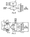
- Fig. 4 shows a further embodiment of a part of the block diagram shown in Fig. 2 or 3;
- Fig. 5 shows a further embodiment of a part of the block diagram shown in Fig. 2 or 3;
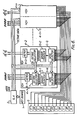
- Fig. 6 shows a block diagram of a further embodiment of the present invention;
- Fig. 7 shows a part of Fig. 6 in greater detail;
- Fig. 8 shows an embodiment of octave selectors for use in Fig. 6;
- Fig. 9 shows a preferred form of decoder used in Fig. 8;
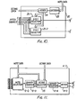
- Fig. 10 shows a further embodiment of octave selectors for use in Fig. 6; and
- Fig. 11 shows yet another embodiment of a tone generator for use in Fig. 6.
- Printed circuit boards are often shared. Fig. 1 shows the usual EMI using the key assigner system disclosed in Japanese patent application number 49-132989. Referring to Fig. 1, 1 is the keyboard. A generator assigner (GA) 2 detects the key stroke and selects a tone generator (TG) 4 not being used out of several TGs, the
GA 2 supplies the assignment signals consisting of (1) note data which represents the note name of the tone signal to be generated by the TG, (2) octave data which represents the octave range of the tone signal to be generated by the TG, and (3) key-on signal which indicates that the key is being pressed.GA 2 may be a circuit which has the same function described in Japanese Patent Publication 50-33407/1975.Circuit 3 is a top octave synthesizer (TOS) which generates the 12 highest pitch signals corresponding to each note (C, C#, - - -, B). 4-1 through 4-n are tone generators which generate tone signals according to the assignment signals supplied by the GA2. Anote selector 5 is controlled by note data supplied byGA 2, and it selects one highest pitch signal out of 12 highest pitch signals supplied byTOS 3. A binary counter 6 consists of a 7-stage toggle flip flop, and it divides the highest pitch signal (applied by a note selector 5) into 7 pitch signals. The frequency of the outputs from terminal QO through Q6 follows the equation below:
- 7-1 through 7-4 are octave selectors which select one pitch signal out of 7 pitch signals supplied by the binary counter 6. The octave data is applied to the octave selector 7-1 through 7-4 as the control input. 8-1 through 8-4 are keyers which control the amplitude of the pitch signals supplied by the octave selectors 7-1 through 7-4. The busbar selector 9-1, 9-2, 9-3 distribute the pitch signals applied by the keyers 8-2 through 8-4 to the output terminals specified by the assignment signals (octave data). Tone color filters are connected to each output terminal.
- The operation of the circuit shown in Fig. 1 is as follows:
- When a key is pressed,
GA 2 supplies the assignment signal to the TG not used. Every key is determined by note name and octave range. In this embodiment, GA 2 supplies note data, octave data and key-on signal. The note data consists of a 4 bit digital signal N0, N1, N2, N3 as shown in Table 1. The octave data consists of a 2 bitdigital signal - On the other side, when TG 4-1 receives the assignment signals, at first, the
note selector 5 selects one highest pitch signal out of 12 highest pitch signals supplied byTOS 3 according to the note data N3 through N0. The binary counter 6 divides the highest pitch signal selected bynote selector 5 and outputs 7 pitch signals from output terminals QO through Q6. The octave selectors 7-1 through 7-4 determine the range of pitch signals in response to theoctave data GA 2. The relation between output signal from terminal X andoctave data octave data - Now the difference in frequency between the each output of octave selectors 7-1 through 7-4 is one octave each, because the same
octave data - If one tries to use the TG surrounded by the dotted line as the quint series TG, TG 4-1 has the following defects.
- TGs 4-1 through 4-n operate correctly as the octave series TG's when both note data and octave data are as shown in Table 1 and 2 respectively. Therefore when the C1 key is pressed, TG 4-1 operates correctly as the quint series TG if
GA 2 supplies note data 1000 and octave data 00, instead of note data 0001 and octave data 00, so allowing the TG to output the 5th higher tone signal. As shown in Table 5,octave data - Concerning the distribution of the pitch signals outputted by the busbar selectors 9-1 through 9-3, terminal XO outputs 5 pitch signals (C1 through E1), but the terminal X3 outputs 19 pitch signals (F3 through B3, C4 through B4). This means the tone color filter connected to the terminal X3 has to take care of 19 tone signals. Therefore the tone color of the highest tone signal outputted by that tone color filter is different from the tone color of the lowest tone signal outputted by that tone color filter.
- Because the tone color filter is selected by the octave data, it outputs the same number of tone signals if the octave data for quint series TG and the octave data for octave series TG are the same. But in that case, the TG generates a tone signal one octave lower than it is supposed to generate for the keys F through B.
- U.S. Patent 4,176,575 discloses a transposing and intramanual coupling control circuit for an electronic keyboard instrument. When a key is depressed a group counter and note counter generate octave data and note data corresponding to the key. The octave data and note data are stored in an assignment memory for the assignment to a tone generator. Transposition (e.g. generation of quint series) is provided by shifting the phasing of the key scanning by the note counter to provide a transposed note number. If the transposed note number associated with a particular key is in the next octave, the octave data from the group counter is adjusted by one as stored in the assignment memory. In a case where the octave data is a 2 bit digital number, the device of U.S. Patent 4,176,573 is open to the same problem of repetition as described above.
- This invention is made to solve the defects described above. The present invention will be made clear by the following detailed description considered together with the accompanying drawings wherein:
- Fig. 2 shows the embodiment of the present invention. Referring to Fig. 2, 4-2 is the TG which generates tone signals according to the assignment signals supplied by
GA 2. 5 is the note selector which selects one highest pitch signal out of 12 highest pitch signals (C, Cg, - - -, B) sent fromTOS 3. The relation between output signal and the note data N3, N2, N1, NO is shown in Table 1. 6 is a binary counter. The binary counter 6 divides the highest pitch signal obtained by thenote selector 5 and supplies 7 pitch signals from the terminal QO through Q6. 7-1 through 7-4 are octave selectors which select one pitch signal out of 4 pitch signals sent from the terminals QO through Q3, Q1 through Q4, Q2 through Q5, Q3 through Q6 respectively of the binary counter 6 according to theoctave data - The operation of the circuit shown in Fig. 2 is as follows.
- When the key is pressed,
GA 2 supplies the assignment signals that correspond to the key being pressed to the TG 4-2. Here, the assignment signals consist of N3, N2, N1, N0, 02, 01, and K0. N3 through NO represent note data, 02 and 01 represent octave data, and KO indicates whether the key is being pressed or not. According to the assignment signals supplied byGA 2,first note selector 5 selects one pitch signal out of 12 highest pitch signals generated byTOS 3. This signal is divided into 7 pitch signals by the binary counter 6 and outputted from the terminals QO through Q6. The relation in frequency of the output from the terminals QO through Q6 is as shown in the equation (1). These signals are supplied to the octave selectors 7-1 through 7-4, whereas: the outputs from the terminals QO through Q3 of the binary counter 6 are connected to the input terminals X3 through XO respectively of the octave selector 7-1, and the outputs from the terminals Q1 through Q4 of the binary counter 6 are connected to the input terminals X3 through XO respectively of the octave selector 7-2, the output from the terminals Q2 through Q5 of the binary counter 6 are connected to the input terminals X3 through XO respectively of the octave selector 7-3, and the output from the terminals Q3 through Q6 of the binary counter 6 are connected to the input terminals X3 through XO respectively of the octave selector 7-4. Each of the octave selectors selects one out of its 4 inputs according to theoctave data - To use the TG 4-2 as the octave series TG, "0" must be given as the O/Q signal. Then the output of the AND gate 11 is always "0" so that each of the 2 to 1 selectors 10-1 and 10-2 always outputs the signal supplied to the terminal X0. This situation is exactly the same as the operation shown in Fig. 1.
- To use the TG 4-2 as the quint series TG, "1" should be given as the
O /Q signal. The output from the AND gate 11 is equal to the MSB of note data N3. Therefore the signal which controls the 2 to 1 selector 10-1 and 10-2 are equal to the note data N3. In the circuit as described above, ifGA 2 supplies the note data shown in Table 5 and the octave data shown in Table 2, TG 4-2 will output the 23' tone signal from theoutput terminal 02, and the 51/3 tone signal'from theoutput terminal 041 through 044 without any defects described in Fig. 1. For example,GA 2 supplies 0001 as the note data, and 00 as the octave data when the key for F1 is pressed. (Theoutput terminals 081 through 084 and 0161 through 0164 output signals but they are not used in this embodiment). - The details of the operation are described as follows.
- Suppose O/Q signal OQ is "1", then the output of AND gate 11 is equal to the note data N3. If the C1 key is pressed in the
keyboard 1,GA 2 supplies 1000 as note data and 00 as octave data. According to the note data,note selector 5 selects the highest pitch signal of the G note generated byTOS 3. The binary counter 6 divides the signal sent fromnote selector 5 and produces 7 octave pitch signals.Octave data C# 1 through E1 keys except the note data is different from the operation of the C1 key. - Next when the key F1 is pressed,
GA 2 supplies 0001 as the note data, and 00 as the octave data to the TG 4-2. For thenote selector 5, binary counter 6, and octave selectors 7-1 through 7-4, everything operates the same as the operation mentioned for the case when the key C1 is pressed, except thenote selector 5 selects the highest pitch signal of C instead of G. Therefore the input terminals XO and X1 of the 2 to 1 selector 10-1 receive the pitch signal outputted by the terminals Q3 and Q4 respectively of the binary counter 6, and the input terminals XO and X1 of the 2 to 1 selector 10-2 receive the pitch signal outputted by the terminal Q4 and Q5 respectively of the binary counter 6. Now, concerning the control signal applied to the 2 to 1 selectors 10-1 and 10-2, the MSB of the note data (N3), which is the input of the AND gate 11, is "0", the output of the AND gate 11 is always "0". Therefore the 2 to 1 selectors 10-1 and 10-2 output the signal applied to the terminal X0, and TG 4-2 outputs the pitch signal sent from the terminals Q3 and Q4 of the binary counter 6 from theoutput terminals GA 2 supplied 0001 as the note data and 01 as the octave data in Fig. 1. But concerning the busbar selector, because it is not necessary to change the octave data as the note name changes from C, to C#, to - - -, to B, as shown in Table 5, the number of pitch signals outputted from each output terminal of the busbar selectors 9-1 through 9-3 is the same and there is no unbalance of distribution. - When the high frequency keys, such as F4 through B4, are pressed, the
octave data bit octave data 02, 01) therefore the repetition of pitch signal does not occur. - Fig. 3 shows another embodiment of the present invention. Referring to Fig. 3, 4-3 is a TG, 5 is a note selector, 6 is a binary counter, 7-1 and 7-2 are octave selectors, 8-1 through 8-4 are keyers, 9-1 through 9-3 are busbar selectors. The operation of the above elements is similar to what is shown in Figs. 1 and 2.12-1 and 12-2 are octave selectors, in this case the octave selectors 12-1 and 12-2 have 3 bits control input. 13 is an adder. Here, the relations between inputs and outputs of
adder 13 and octave selectors 12-1 and 12-2 are as shown in Tables 8 and 9, respectively. - The operation of the circuit shown in Fig. 3 is as follows:
- According to the note data N3 through N1,
note selector 5 selects one of the highest frequency pitch signals C through B which are generated byTOS 3. Then the selected highest frequency pitch signal is divided into 7 pitch signals and outputted from the terminals QO through Q6 by binary counter 6. The octave selectors 7-1, 7-2, 12-1 and 12-2 select one pitch signal out of QO through Q6. - The operation of octave selectors 12-1 and 12-2 is as follows.
- O/Q signal OQ is applied to the
inverter 14, and the output of theinverter 14 and the MSB of the note data N3 are applied to the NOR gate 15. Then the output of the NOR gate 15 is applied to the input B of theadder 13. Theadder 13 outputs the addition ofoctave data adders 13 C0, C1 and C2 are equal tooctave data 01,octave data 02, and "0", respectively. In other words, octave selectors 12-1 and 12-2 output the signal applied to input terminal XO from the output terminal X while octave selectors 7-1, 7-2 output the signal applied to input terminal XO from the output terminal X. This operation of the octave selectors 12-1, 12-2, 7-1 and 7-2 exactly the same as octave series TG. - When the O/Q signal OQ is "1" the situation is as follows:
- The output of the NOR gate 15 is the inverse of note data N3 so that, as shown in Table 10, the output is "0" when the keys C through E are pressed and is "1" when keys F through B are pressed. This output is connected to the
adder 13. Theadder 13 outputs octave data without any change when the keys C through E are pressed, and theadder 13 outputs the sum of 1 and octave data when the keys F through B are pressed. Therefore octave selectors 12-1 and 12-2 select a pitch signal one octave higher for F through B keys compared with C through E keys. The operation of the octave selectors 12-1 and 12-2 is similar to the output of 2 to 1 selectors 10-1 and. 10-2 shown in Fig. 2. Thus the octave selectors' 12-1 and 12-2 output pitch signals for 2§', 5131, respectively. The operation of the keyers 8-1 through 8-4 and the busbar selectors 9-1 through 9-3 is the same as described in Fig. 2. - Besides, in embodiments shown in Fig. 2 and Fig. 3, 7 pitch signals (the outputs the binary counter 6) are obtained by dividing the highest pitch signals selected out of 12 highest pitch signals (C through B) supplied from the
TOS 3 by thenote selector 5. This operation done by theTOS 3, thenote selector 5, and the binary counter 6 may be replaced with the circuit shown in Fig. 4 or Fig. 5. - In the embodiment shown in Fig. 4, 16 is a programmable counter. It divides the master clock by N to obtain the highest pitch signal of the note specified by the key stroke. The value of N is determined by the data supplied by the Read Only Memory (ROM) 17. The ROM 17 has the note data N3 through NO as addressing inputs. Therefore the value of N of the
programmable counter 16 varies according to the note data in order to obtain the highest pitch signal of the note specified by the key stroke. Binary counter 6 divides the highest pitch signal obtained by theprogrammable counter 16 tooutput 7 pitch signals. - In the embodiment shown in Fig. 5, the binary counters 6-1 through 6-12 divide the highest pitch signal supplied by
TOS 3 to obtain the 7 pitch signals respectively. The multiplexers (MPX) 18-1 through 18-12 multiplex the 7 pitch signals applied by the binary counters 6-1 through 6-12 respectively. Then in TG 4-4,note selector 7 selects one of the multiplexed pitch signals according to the note data. Demultiplexer (DMPX) 19 demultiplexes the signal applied by thenote selector 5 to obtain the 7 pitch signals. - Besides, the
programmable counter 16 may be a usual type programmable counter such as RCA's CMOS integrated circuit CD-4059A. - Fig. 6 is another embodiment of the present invention. For the device or circuit which operates the same as described previously, the same notation will be taken and no detail description will be done. Referring to Fig. 6, the TG 4-1 is the TG for octave series, and the TG 4-2 is the TG for quint series. In the following description, the assignment signals supplied by the
GA 2 are assumed to be the same as shown in Table 1 and 2. - TG 4-1 and 4-2 operate as follows. At the moment of key stroke,
GA 2 supplies to assignment signals to TG 4-1 and 4-2. Note selectors 5-N and 5-Q each selects the highest pitch signal sent fromTOS 3 according to the note data. In this embodiment, the same note data is applied to both note selectors 5-N and 5-Q, however, each note selector is made to select different highest pitch signals. Fig. 7 shows the detail of note selectors 5-N and 5-Q. In Fig. 7, the note selectors 5-N and 5-Q are the same circuit, and select one out of 12 inputs (X1 through X12) according to the control signal (here, the note data N3 through NO) applied to terminals A through D. The truth table of this note selector is shown in Table 11. As shown in Fig. 7, the inputs to the note selector 5-Q (highest pitch signals C through Flt) are shifted to the right and highest pitch signals G through B are connected to the terminals X1 through X5 respectively so as to select the highest pitch signal different from that selected by note selector 5-N, even though it is controlled by the same note data. - TG 4-1 which is for octave series TG, has no difference from the usual TG. The operation of the quint series TG 4-2 is as follows:
- As mentioned earlier, the note selector 5-Q selects the highest pitch signal from several pitch signals to supply them to
octave selector 20.GA 2 supplies the octave data and note data to TG 4-2. The octave data is the same as that supplied tooctave selector 7. The note data is the same as that one supplied to note selector 5-N. Therefore theoctave selector 20 selects pitch signals determined by octave data as shown in Table 2 and modified by note data to supply keyer 8-2. Then keyer 8-2 controls the amplitude of pitch signals to output from TG 4-2. - Describing
octave selector 20, when the note data is 0110 through 1100, which means the keys F through B are pressed, it selects the pitch signal whose octave range is one octave higher than the octave range determined only by the octave data. Therefore TG 4-2 generates pitch signals naturally so that the output fromoctave selector 20 rises a half tone without lowering one octave when the key E, then the key F (which is next to the key E) are pressed. - By constraining the TG to operate as described, the problem of the TG generating pitch signals one octave lower than it should is avoided. Both octave series tone signals and quint series tone signals can be obtained without increasing the TOS.
- Fig. 8 shows an embodiment of
octave selector 20 shown in Fig. 6. Referring to Fig. 8, 21-1 through 21-3 are 4 to 1 selectors which select one out of 4 inputs according to the octave data. 22 is a decoder which outputs "1" or "0" according to the note data. The truth table of thedecoder 22 is shown in Table 12 (col. of decoder 22). - The operation of what is shown in Fig. 8 is as follows.
- Each of 4 to 1 selectors 21-1 through 21-3 selects one pitch signal from the 4 pitch signals applied to them according to the octave data. Each of the outputs of the 4 to 1 selectors 21-1 through 21-3 differs one octave, and the input to terminal XO of the 2 to 1 selectors 10-1 and 10-2 is one octave higher than input to terminal X1. And note data is applied to
decoder 22 to control the outputs ofoctave selector 20. The decoder can be a logic circuit as shown in Fig. 9. - Fig. 10 is another embodiment of the quint
series octave selector 20 shown in Fig. 6. In Fig. 10, 23 is a decoder which outputs "0" or "1" according to note data, and its truth table is shown in Table 12 (col. of decoder 23). 24 is an adder which takes the sum of the octave data and output of decoder 23. 25-1 and 25-2 are 5 to 1 selectors which select one pitch signal out of 5 pitch signals according toadder 24. - The operation of what is shown in Fig. 10 is as follows.
- When the note data is 0110 through 1100, decoder 23, supplies "1" to adder 24. Then adder 24 adds 1 to the octave data and supplies it to the 5 to 1 selectors 25-1 and 25-2 to select pitch signals which are one octave higher than the pitch signals determined by the original octave data.
- Besides, the decoder circuit shown in Fig. 9 is only for the case when the
GA 2 supplies the note data as shown in Table 1. It is obvious that the note data may be encoded in any format, therefore if note data were determined as shown in Table 13, then MSB of the note data, which means the data N3, can control the 2 to 1 selectors 10-1 and 10-2 directly. - In the description above, the embodiment shown selects pitch signals one octave higher according to the note data by controlling the octave data or octave selector. But the TG could easily and naturally be constructed so as to have octave selector which selects a pitch signal out of pitch signals which are made one octave higher beforehand according to the note data.
- Fig. 11 is an embodiment for the case when the octave selector selects the pitch signal out of pitch signals which are made one octave higher beforehand according to the note data. In Fig. 11, an input signal of binary counter 6-4 is selected by both octave data and note data and applied to
octave selector 20. - As described above, by controlling the octave range of pitch signals with both octave data and note data, the present invention will provide octave series tone signals and quint series tone signals without designing another TG circuit. And for the quint series tone signals, they are not pure temperament so tone signals not beating when they must does not occur. And it is not necessary to raise the frequency of the clock signal as described in the usual EMI, therefore, a device for high frequency signals is not necesary. And the same octave data can be applied to both the octave series TG and the quint series TG without generating any pitch signal which has wrong octave number, therefore the unbalance in distribution by busbar selectors is avoided without any hardware.


Claims (6)
Applications Claiming Priority (4)
| Application Number | Priority Date | Filing Date | Title |
|---|---|---|---|
| JP5121680A JPS56147190A (en) | 1980-04-17 | 1980-04-17 | Electronic music instrument |
| JP51216/80 | 1980-04-17 | ||
| JP5203580A JPS56147195A (en) | 1980-04-18 | 1980-04-18 | Electronic music instrument |
| JP52035/80 | 1980-04-18 |
Publications (3)
| Publication Number | Publication Date |
|---|---|
| EP0038675A2 EP0038675A2 (en) | 1981-10-28 |
| EP0038675A3 EP0038675A3 (en) | 1983-02-02 |
| EP0038675B1 true EP0038675B1 (en) | 1986-08-20 |
Family
ID=26391750
Family Applications (1)
| Application Number | Title | Priority Date | Filing Date |
|---|---|---|---|
| EP81301665A Expired EP0038675B1 (en) | 1980-04-17 | 1981-04-15 | Electronic musical instrument |
Country Status (4)
| Country | Link |
|---|---|
| US (1) | US4380184A (en) |
| EP (1) | EP0038675B1 (en) |
| CA (1) | CA1167294A (en) |
| DE (1) | DE3175146D1 (en) |
Families Citing this family (1)
| Publication number | Priority date | Publication date | Assignee | Title |
|---|---|---|---|---|
| JPS58169194A (en) * | 1982-03-31 | 1983-10-05 | 日本ビクター株式会社 | Electronic musical instrument |
Citations (1)
| Publication number | Priority date | Publication date | Assignee | Title |
|---|---|---|---|---|
| JPS49132989A (en) * | 1973-04-25 | 1974-12-20 |
Family Cites Families (4)
| Publication number | Priority date | Publication date | Assignee | Title |
|---|---|---|---|---|
| US3610799A (en) * | 1969-10-30 | 1971-10-05 | North American Rockwell | Multiplexing system for selection of notes and voices in an electronic musical instrument |
| US4070943A (en) * | 1975-09-05 | 1978-01-31 | Faulkner Alfred H | Electronic organ keying system |
| US4282785A (en) * | 1977-10-17 | 1981-08-11 | Kabushiki Kaisha Kawai Gakki Seisakusho | Electronic musical instrument |
| US4176573A (en) * | 1978-10-13 | 1979-12-04 | Kawai Musical Instrument Mfg. Co. Ltd. | Intrakeyboard coupling and transposition control for a keyboard musical instrument |
-
1981
- 1981-04-14 US US06/254,152 patent/US4380184A/en not_active Expired - Lifetime
- 1981-04-15 DE DE8181301665T patent/DE3175146D1/en not_active Expired
- 1981-04-15 EP EP81301665A patent/EP0038675B1/en not_active Expired
- 1981-04-16 CA CA000375640A patent/CA1167294A/en not_active Expired
Patent Citations (1)
| Publication number | Priority date | Publication date | Assignee | Title |
|---|---|---|---|---|
| JPS49132989A (en) * | 1973-04-25 | 1974-12-20 |
Also Published As
| Publication number | Publication date |
|---|---|
| US4380184A (en) | 1983-04-19 |
| DE3175146D1 (en) | 1986-09-25 |
| EP0038675A3 (en) | 1983-02-02 |
| CA1167294A (en) | 1984-05-15 |
| EP0038675A2 (en) | 1981-10-28 |
Similar Documents
| Publication | Publication Date | Title |
|---|---|---|
| US4628789A (en) | Tone effect imparting device | |
| EP0206786B1 (en) | Tone signal generation device | |
| US4437379A (en) | Electronic musical instrument of waveform memory readout type | |
| US3743756A (en) | Method of producing tones of a preferably substantially equal-tempered scale | |
| US4176573A (en) | Intrakeyboard coupling and transposition control for a keyboard musical instrument | |
| US3875842A (en) | Multiplexing system for selection of notes in an electronic musical instrument | |
| US4416179A (en) | Electronic musical instrument | |
| EP0035636A1 (en) | Chord generating apparatus of electronic musical instrument | |
| US3499090A (en) | Electronic organ frequency dividing system employing division by odd numbers | |
| US5218156A (en) | Apparatus for combining stored waveforms to synthesize musical tones | |
| US4890527A (en) | Mixing type tone signal generation device employing two channels generating tones based upon different parameter | |
| US3992973A (en) | Pulse generator for an electronic musical instrument | |
| US4380184A (en) | Electronic musical instrument | |
| US4203337A (en) | Large scale integrated circuit chip for an electronic organ | |
| US4223584A (en) | Electronic musical instrument | |
| CA1160873A (en) | Electronic musical instrument | |
| US4144787A (en) | Keyer circuit for electronic organ | |
| US4256002A (en) | Large scale integrated circuit generator chip for electronic organ | |
| US4174649A (en) | Electronic musical instrument | |
| EP0038707B1 (en) | Electronic musical instrument | |
| US4186635A (en) | Electronic musical instrument | |
| US4393740A (en) | Programmable tone generator | |
| JPH03204697A (en) | Musical sound signal generating device | |
| JPS637397B2 (en) | ||
| JPH027077B2 (en) |
Legal Events
| Date | Code | Title | Description |
|---|---|---|---|
| PUAI | Public reference made under article 153(3) epc to a published international application that has entered the european phase |
Free format text: ORIGINAL CODE: 0009012 |
|
| AK | Designated contracting states |
Designated state(s): DE GB IT NL |
|
| PUAL | Search report despatched |
Free format text: ORIGINAL CODE: 0009013 |
|
| AK | Designated contracting states |
Designated state(s): DE GB IT NL |
|
| 17P | Request for examination filed |
Effective date: 19830728 |
|
| GRAA | (expected) grant |
Free format text: ORIGINAL CODE: 0009210 |
|
| AK | Designated contracting states |
Kind code of ref document: B1 Designated state(s): DE GB IT NL |
|
| ITF | It: translation for a ep patent filed | ||
| REF | Corresponds to: |
Ref document number: 3175146 Country of ref document: DE Date of ref document: 19860925 |
|
| PLBE | No opposition filed within time limit |
Free format text: ORIGINAL CODE: 0009261 |
|
| STAA | Information on the status of an ep patent application or granted ep patent |
Free format text: STATUS: NO OPPOSITION FILED WITHIN TIME LIMIT |
|
| 26N | No opposition filed | ||
| ITTA | It: last paid annual fee | ||
| ITPR | It: changes in ownership of a european patent |
Owner name: OFFERTA DI LICENZA AL PUBBLICO |
|
| REG | Reference to a national code |
Ref country code: GB Ref legal event code: 746 Effective date: 19951123 |
|
| PGFP | Annual fee paid to national office [announced via postgrant information from national office to epo] |
Ref country code: GB Payment date: 19960409 Year of fee payment: 16 |
|
| PGFP | Annual fee paid to national office [announced via postgrant information from national office to epo] |
Ref country code: DE Payment date: 19960418 Year of fee payment: 16 |
|
| PGFP | Annual fee paid to national office [announced via postgrant information from national office to epo] |
Ref country code: NL Payment date: 19960430 Year of fee payment: 16 |
|
| PG25 | Lapsed in a contracting state [announced via postgrant information from national office to epo] |
Ref country code: GB Effective date: 19970415 |
|
| PG25 | Lapsed in a contracting state [announced via postgrant information from national office to epo] |
Ref country code: NL Effective date: 19971101 |
|
| GBPC | Gb: european patent ceased through non-payment of renewal fee |
Effective date: 19970415 |
|
| PG25 | Lapsed in a contracting state [announced via postgrant information from national office to epo] |
Ref country code: DE Free format text: LAPSE BECAUSE OF NON-PAYMENT OF DUE FEES Effective date: 19980101 |
|
| NLV4 | Nl: lapsed or anulled due to non-payment of the annual fee |
Effective date: 19971101 |