EP0038338B1 - Transition connector - Google Patents
Transition connector Download PDFInfo
- Publication number
- EP0038338B1 EP0038338B1 EP80902006A EP80902006A EP0038338B1 EP 0038338 B1 EP0038338 B1 EP 0038338B1 EP 80902006 A EP80902006 A EP 80902006A EP 80902006 A EP80902006 A EP 80902006A EP 0038338 B1 EP0038338 B1 EP 0038338B1
- Authority
- EP
- European Patent Office
- Prior art keywords
- terminals
- transition connector
- feature
- distance
- edge
- Prior art date
- Legal status (The legal status is an assumption and is not a legal conclusion. Google has not performed a legal analysis and makes no representation as to the accuracy of the status listed.)
- Expired
Links
Images
Classifications
-
- H—ELECTRICITY
- H01—ELECTRIC ELEMENTS
- H01R—ELECTRICALLY-CONDUCTIVE CONNECTIONS; STRUCTURAL ASSOCIATIONS OF A PLURALITY OF MUTUALLY-INSULATED ELECTRICAL CONNECTING ELEMENTS; COUPLING DEVICES; CURRENT COLLECTORS
- H01R4/00—Electrically-conductive connections between two or more conductive members in direct contact, i.e. touching one another; Means for effecting or maintaining such contact; Electrically-conductive connections having two or more spaced connecting locations for conductors and using contact members penetrating insulation
- H01R4/24—Connections using contact members penetrating or cutting insulation or cable strands
- H01R4/2416—Connections using contact members penetrating or cutting insulation or cable strands the contact members having insulation-cutting edges, e.g. of tuning fork type
- H01R4/242—Connections using contact members penetrating or cutting insulation or cable strands the contact members having insulation-cutting edges, e.g. of tuning fork type the contact members being plates having a single slot
- H01R4/2425—Flat plates, e.g. multi-layered flat plates
- H01R4/2429—Flat plates, e.g. multi-layered flat plates mounted in an insulating base
- H01R4/2433—Flat plates, e.g. multi-layered flat plates mounted in an insulating base one part of the base being movable to push the cable into the slot
Definitions
- This invention relates to electrical connectors, and more particularly to connectors for use with multiple conductive elements having different pitch or spacing.
- DE-A-2738869 discloses a transitional connector having identical contacts which terminate along a flat path but in this reference the contact terminals are bent sideways so as to provide terminals with an offset so that the upper row of terminals has a different spacing to that of the lower row.
- Such a connector of DE-A-2738869 is difficult to manufacture.
- the present invention seeks to provide an improved transition connector in which change of pitch is performed by a group of identical contact elements the length of the elements being equal and to provide an improved support structure for such elements.
- the present invention is characterised by a support member comprising an inner flat carrier body member having a crenelated lower edge and which is fitted within an outer trough-like container having a perforated base and multinotched upper inner edge, the crenels of the lower edge being spaced apart by a second distance to receive the lower terminals, the notches of the upper edge being spaced apart by a first distance to receive the upper terminals, the lower terminals fitting within perforations in the base of the container, said carrier body being channelled along its edge to provide free space for the deformable flat straps of the contact elements.
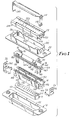
- Figure 1 is an exploded view in perspective indicating the components and arrangements of one form of connector
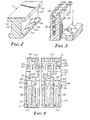
- Figure 2 is a partial view in perspective of the contact carrier component
- Figure 3 is a partial view in perspective of the insulating container component
- Figure 4 is a partial longitudinal sectional elevation of the assembled connector of Figure 1
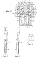
- Figure 5 is a partial transverse sectional elevation of the assembled connector of Figure 1
- Figure 6 is a front elevation
- Figure 7 a side elevation, of another form of contact element
- Figure 8 is a plan view of anchoring means as carried by the contact elements of Figures 4-7.
- the connector illustrated in Figure 1 will be seen to consist of a lower shell 10, a lower insulator 12, a trough-like insulating container 14, an insulating contact element carrier 16, a plurality of contact elements 18, an upper shell 20, an insulating cover 22, a strain relief spring clamp 24 and retaining clips 26. Certain of these components are illustrated and described in greater detail in connection with the other figures. Designations such for example as “upper” and “lower” are supplied for convenience and will be understood to refer only to the positions shown in the drawings.
- contact elements 18 are first applied and anchored to insulating carrier 16, which is then inserted within trough-like container 14.
- Clips 26 are applied to the ends of the composite and the whole is inserted into upper shell 20.
- Lower insulator 12 is inserted in lower shell 10, with edge ridges 121 pressing against the inner edges 101 of the shell and with the top of the insulator fitted against the bottom of the upper assembly; and the two shells are fastened together.
- Attachment to an appropriate flat cable is accomplished by compressing the cable between the upper surface of the connector and the lower surface of the cover 22. For some installations the cable is folded back over the top of the cover, and a spring clamp 24 is then applied to hold the cable securely in place.
- Carrier 16 is more clearly shown in Figure 2 to have the general shape of an I-beam, having along both longitudinal edges continuous upper overhangs 162 and interrupted or crenelate lower overhangs 164 defining a central channel 169. Above and to the side of each crenel or notch 166 in the lower overhang there is provided a perforation 168 in the central beam, for a purpose which will be made apparent.
- the trough-like container 14 is notched long both upper inner edges at notches 142 and the bottom 144 is correspondingly perforate at perforations 146 (see Figure 3).
- the side walls are grooved near their ends at grooves 148 ( Figure 1) to receive arms 261 of clips 26 which fit against the appropriately shaped ends of carrier 16 and cover 22, the bosses 221 of the latter fitting within slots 262 of the clips.
- the lower of slots 262 also receives the turned edges 242 of the clamp 24 when used.
- Elongate bosses 150 along the upper outer wall edges of container 14 rest against the depressed side walls 202 of the upper shell 20, and corner braces 201 of the shell press against the upper corners of container 14 and carrier 16, holding the insulative components firmly together and within the shell.
- contact element 18 shown in detail in Figures 14 and 5 is designed to make connection between a wire conductor and a pin or male contact member.
- the element includes an upper bifurcate plate or U-contact terminal 181, for example as described in U.S.-A-3,189,863 or U.S.-A-3,444,506, and a lower split tubular socket or female terminal 182.
- the two are connected together by an intervening flat deformable strap 183.
- a barbed bifurcate plate 184 extends from near the juncture of the strap and one of the terminals and across and beyond the width of the strap.
- the tubular terminal 182 joins the strap 183 through a connecting strip 185 from the upper edge of which the plate 184 extends.
- Strip 185 is centrally narrowed at arcuate indentations 186 to facilitate conversion from the arcuate shape at the top of the tubular terminal to the flat shape at the juncture with the anchor plate 1 84.
- the lower end of the strap 183 fits snugly within the slot 166.
- the terminal is firmly held against axial movement by contact of the top of the tubular terminal 182 with the bottoms of the crenels 164 and by the anchoring effect of the plate 184 and strip 185.
- An important feature of these contact elements is that they are formable from a single flat plate of metal.
- the anchor plate 184 is inserted in the aperture 168.
- the bifurcate structure permits the plate to compress slightly during insertion, and the barbs 187 then securely retain the plate within the aperture. By this means the several contact elements are held in place against the carrier 16 during further manipulation.
- the tubular terminals 182 are inserted through the apertures 146 in the base 144 of the container 14 and lie within corresponding holes 122 in the lower insulator 12, being accessible through the slightly constricted openings 123.
- the U-contacts 181 fit into the notches 142 in the inner walls of the container 14 and against the outer face of the upper overhang 162.
- the lower edge of the U-contact rests against the lower surface of the notched area, and the upper extension of the strap 183 to which the U-contact is attached rests against the lower face of the overhang, thereby confining the U-contact against axial movement.
- the deformable or foldable strap 183 connecting terminals 181 and 182 lies within the channel 169, with sufficient space to ensure freedom to fold without contacting any adjacent contact element.
- the cover 22 contains slot-like perforations 222 open at the surface adjacent the carrier 16 and at locations corresponding to the position of the notches 142, and into which the U-contacts 181 extend.
- the perforations are dimensioned to provide a close fit against the flat sides of the contacts but to permit the required degree of edgewise expansion of the contacts when the latter are forced over the wires of a cable.
- Test openings 223 permitting the introduction of a test probe to the contact area may be incorporated if desired.
- the lower surface of the cover 22 may also be formed with transverse alternate ridges 225 and grooves 226 corresponding to the longitudinal ridges and grooves of a multi-conductor flat cable.
- the cover is further provided with stepped ends 224 corresponding with the positions of the corner braces 201, the intervening longitudinal distance being equal to the width of the flat cable to which connection is desired. It is sometimes helpful to add a thin layer of pressure-sensitive adhesive over the cable-contacting surface of the cover, to impart further holding properties useful particularly during application of the connector to a cable.
- the pitch or spacing of the upper terminals will differ from that of the lower.
- the U-contacts of the connector as just described may be either closer together or farther apart than are the tubular contacts.
- the terminals For purposes of making effective contact both with a cable and with another pin or tube connector, the terminals must be perpendicular to parallel planes, i.e. to the parallel upper and lower faces of the carrier 16.
- the tips of the upper terminals should lie in a flat plane to assure proper contact with the flat cable.
- the tips of tubular or pin type terminals should also lie in a flat plane to assure proper contact and closure with a complementary pin or tube connector and without requiring tubes or pins of undue length.
- a pin or male terminal 192 replaces the split tubular terminal 182 of element 18, the remaining components being identical.
- the pin type terminal is used, the lower insulator is eliminated, and the lower shell 10 is replaced by an otherwise similar shell, not shown, having a larger opening and capable of fitting closely about the dependent portion of a lower shell 10 or that of another similarly dimensioned connector having female or tube type terminals.
- a connector as hereinabove described contains a total of 25 contact elements having U-contact upper and female tubular lower terminals, located in two parallel rows of 12 and 13 elements respectively.
- the upper rows are spaced apart 4.9 mm. and the terminals are spaced apart 2.5 mm. in each row, center to center.
- the lower rows are spaced 2.85 mm. apart and the terminals 2.8 mm. in each row, center to center.
- the assembly is used for transition between the wires of a flat cable 31.75 mm. in width and typically containing 25 No. 28 B & S gauge wires at a pitch (center to center spacing) of 1.27 mm., and a standard pin type connector having a pitch of 1.37 mm.
- transition connectors embodying the same principles may be constructed for interconnecting directly between two cables as well as for interconnecting between standard pin or tube type connectors of different pitch.
- change in pitch is accomplished with a group of identical contact elements and in a structure wherein the extended length of all terminals of each form is identical.
Abstract
Description
- This invention relates to electrical connectors, and more particularly to connectors for use with multiple conductive elements having different pitch or spacing.
- Flat cable is available in various pitches, and various means for interconnecting the conductors of such cables, or of a cable with a connector of a different pitch, have been described. Where the pitch of one cable is one-half that of the other, the adapter of U.S.-A-3,777,299 is useful. In the more usual case wherein the pitch of one cable is not a multiple of that of the other, connectors as described in U.S.-A-3,990,767 and U.S.-A-4,147,399 have been suggested. The former employs a series of identical double-ended contact elements, the two ends being connected by hinged rigid parallel plates, one set of ends progressively diverging from axial alignment with the other set of ends and thus terminating along an arcuate path. In the structure of U.S.-A-4,147,399, both sets of ends terminate along a flat path but the contact elements are not identical.
- The foregoing difficulties are substantially overcome by DE-A-2738869 which discloses a transitional connector having identical contacts which terminate along a flat path but in this reference the contact terminals are bent sideways so as to provide terminals with an offset so that the upper row of terminals has a different spacing to that of the lower row. Such a connector of DE-A-2738869 is difficult to manufacture.
- The present invention seeks to provide an improved transition connector in which change of pitch is performed by a group of identical contact elements the length of the elements being equal and to provide an improved support structure for such elements.
- Accordingly the present invention is characterised by a support member comprising an inner flat carrier body member having a crenelated lower edge and which is fitted within an outer trough-like container having a perforated base and multinotched upper inner edge, the crenels of the lower edge being spaced apart by a second distance to receive the lower terminals, the notches of the upper edge being spaced apart by a first distance to receive the upper terminals, the lower terminals fitting within perforations in the base of the container, said carrier body being channelled along its edge to provide free space for the deformable flat straps of the contact elements.
- The invention will be further described in conjunction with the accompanying drawings, in which Figure 1 is an exploded view in perspective indicating the components and arrangements of one form of connector, Figure 2 is a partial view in perspective of the contact carrier component, Figure 3 is a partial view in perspective of the insulating container component, Figure 4 is a partial longitudinal sectional elevation of the assembled connector of Figure 1, Figure 5 is a partial transverse sectional elevation of the assembled connector of Figure 1, Figure 6 is a front elevation, and Figure 7 a side elevation, of another form of contact element, and Figure 8 is a plan view of anchoring means as carried by the contact elements of Figures 4-7.
- The connector illustrated in Figure 1 will be seen to consist of a
lower shell 10, alower insulator 12, a trough-like insulatingcontainer 14, an insulatingcontact element carrier 16, a plurality ofcontact elements 18, anupper shell 20, an insulatingcover 22, a strainrelief spring clamp 24 and retaining clips 26. Certain of these components are illustrated and described in greater detail in connection with the other figures. Designations such for example as "upper" and "lower" are supplied for convenience and will be understood to refer only to the positions shown in the drawings. - In assembling the connector of Figure 1,
contact elements 18 are first applied and anchored to insulatingcarrier 16, which is then inserted within trough-like container 14.Clips 26 are applied to the ends of the composite and the whole is inserted intoupper shell 20.Lower insulator 12 is inserted inlower shell 10, withedge ridges 121 pressing against theinner edges 101 of the shell and with the top of the insulator fitted against the bottom of the upper assembly; and the two shells are fastened together. Attachment to an appropriate flat cable is accomplished by compressing the cable between the upper surface of the connector and the lower surface of thecover 22. For some installations the cable is folded back over the top of the cover, and aspring clamp 24 is then applied to hold the cable securely in place. -
Carrier 16 is more clearly shown in Figure 2 to have the general shape of an I-beam, having along both longitudinal edges continuousupper overhangs 162 and interrupted or crenelatelower overhangs 164 defining acentral channel 169. Above and to the side of each crenel or notch 166 in the lower overhang there is provided aperforation 168 in the central beam, for a purpose which will be made apparent. - The trough-
like container 14 is notched long both upper inner edges atnotches 142 and the bottom 144 is correspondingly perforate at perforations 146 (see Figure 3). The side walls are grooved near their ends at grooves 148 (Figure 1) to receivearms 261 ofclips 26 which fit against the appropriately shaped ends ofcarrier 16 andcover 22, thebosses 221 of the latter fitting withinslots 262 of the clips. The lower ofslots 262 also receives the turnededges 242 of theclamp 24 when used.Elongate bosses 150 along the upper outer wall edges ofcontainer 14 rest against thedepressed side walls 202 of theupper shell 20, and corner braces 201 of the shell press against the upper corners ofcontainer 14 andcarrier 16, holding the insulative components firmly together and within the shell. - The form of
contact element 18 shown in detail in Figures 14 and 5 is designed to make connection between a wire conductor and a pin or male contact member. For such purpose the element includes an upper bifurcate plate orU-contact terminal 181, for example as described in U.S.-A-3,189,863 or U.S.-A-3,444,506, and a lower split tubular socket orfemale terminal 182. The two are connected together by an intervening flatdeformable strap 183. A barbedbifurcate plate 184 extends from near the juncture of the strap and one of the terminals and across and beyond the width of the strap. - The
tubular terminal 182 joins thestrap 183 through a connectingstrip 185 from the upper edge of which theplate 184 extends.Strip 185 is centrally narrowed atarcuate indentations 186 to facilitate conversion from the arcuate shape at the top of the tubular terminal to the flat shape at the juncture with the anchor plate 1 84. The lower end of thestrap 183 fits snugly within theslot 166. The terminal is firmly held against axial movement by contact of the top of thetubular terminal 182 with the bottoms of thecrenels 164 and by the anchoring effect of theplate 184 andstrip 185. An important feature of these contact elements is that they are formable from a single flat plate of metal. - As shown more particularly in Figure 5, the
anchor plate 184 is inserted in theaperture 168. The bifurcate structure permits the plate to compress slightly during insertion, and thebarbs 187 then securely retain the plate within the aperture. By this means the several contact elements are held in place against thecarrier 16 during further manipulation. - The
tubular terminals 182 are inserted through theapertures 146 in thebase 144 of thecontainer 14 and lie withincorresponding holes 122 in thelower insulator 12, being accessible through the slightlyconstricted openings 123. - The U-contacts 181 fit into the
notches 142 in the inner walls of thecontainer 14 and against the outer face of theupper overhang 162. The lower edge of the U-contact rests against the lower surface of the notched area, and the upper extension of thestrap 183 to which the U-contact is attached rests against the lower face of the overhang, thereby confining the U-contact against axial movement. - The deformable or
foldable strap 183 connectingterminals channel 169, with sufficient space to ensure freedom to fold without contacting any adjacent contact element. - The
cover 22 contains slot-like perforations 222 open at the surface adjacent thecarrier 16 and at locations corresponding to the position of thenotches 142, and into which theU-contacts 181 extend. The perforations are dimensioned to provide a close fit against the flat sides of the contacts but to permit the required degree of edgewise expansion of the contacts when the latter are forced over the wires of a cable.Test openings 223 permitting the introduction of a test probe to the contact area may be incorporated if desired. - The lower surface of the
cover 22 may also be formed with transversealternate ridges 225 andgrooves 226 corresponding to the longitudinal ridges and grooves of a multi-conductor flat cable. As here illustrated, the cover is further provided withstepped ends 224 corresponding with the positions of thecorner braces 201, the intervening longitudinal distance being equal to the width of the flat cable to which connection is desired. It is sometimes helpful to add a thin layer of pressure-sensitive adhesive over the cable-contacting surface of the cover, to impart further holding properties useful particularly during application of the connector to a cable. - For a transition connector it is to be understood that the pitch or spacing of the upper terminals will differ from that of the lower. Thus the U-contacts of the connector as just described may be either closer together or farther apart than are the tubular contacts. For purposes of making effective contact both with a cable and with another pin or tube connector, the terminals must be perpendicular to parallel planes, i.e. to the parallel upper and lower faces of the
carrier 16. The tips of the upper terminals should lie in a flat plane to assure proper contact with the flat cable. The tips of tubular or pin type terminals should also lie in a flat plane to assure proper contact and closure with a complementary pin or tube connector and without requiring tubes or pins of undue length. These several requirements are met in the devices of the present invention. - It is usually most convenient to arrange a central contact element with its two terminals on the same axis. Assuming the pitch of the lower terminals to be greater than those of the upper terminals, it will be apparent that planar positioning of the terminal tips will require that maximum folding or deformation of the connecting straps must occur at said central contact element, and minimum folding at elements farthest removed therefrom. An intermediate degree of relative displacement of terminals and folding of
straps 183 is illustrated in Figure 4. - In the
contact element 19 of Figures 6 and 7 a pin ormale terminal 192 replaces the splittubular terminal 182 ofelement 18, the remaining components being identical. Where the pin type terminal is used, the lower insulator is eliminated, and thelower shell 10 is replaced by an otherwise similar shell, not shown, having a larger opening and capable of fitting closely about the dependent portion of alower shell 10 or that of another similarly dimensioned connector having female or tube type terminals. - In a specific illustrative example, a connector as hereinabove described contains a total of 25 contact elements having U-contact upper and female tubular lower terminals, located in two parallel rows of 12 and 13 elements respectively. The upper rows are spaced apart 4.9 mm. and the terminals are spaced apart 2.5 mm. in each row, center to center. The lower rows are spaced 2.85 mm. apart and the terminals 2.8 mm. in each row, center to center. The assembly is used for transition between the wires of a flat cable 31.75 mm. in width and typically containing 25 No. 28 B & S gauge wires at a pitch (center to center spacing) of 1.27 mm., and a standard pin type connector having a pitch of 1.37 mm.
- In the light of the foregoing detailed description it will be apparent that transition connectors embodying the same principles may be constructed for interconnecting directly between two cables as well as for interconnecting between standard pin or tube type connectors of different pitch. In all such modifications, change in pitch is accomplished with a group of identical contact elements and in a structure wherein the extended length of all terminals of each form is identical.
Claims (7)
Applications Claiming Priority (2)
| Application Number | Priority Date | Filing Date | Title |
|---|---|---|---|
| US06/090,149 US4470655A (en) | 1979-11-01 | 1979-11-01 | Transition connector |
| US90149 | 1979-11-01 |
Publications (3)
| Publication Number | Publication Date |
|---|---|
| EP0038338A1 EP0038338A1 (en) | 1981-10-28 |
| EP0038338A4 EP0038338A4 (en) | 1982-03-29 |
| EP0038338B1 true EP0038338B1 (en) | 1984-06-27 |
Family
ID=22221530
Family Applications (1)
| Application Number | Title | Priority Date | Filing Date |
|---|---|---|---|
| EP80902006A Expired EP0038338B1 (en) | 1979-11-01 | 1981-05-19 | Transition connector |
Country Status (11)
| Country | Link |
|---|---|
| US (1) | US4470655A (en) |
| EP (1) | EP0038338B1 (en) |
| JP (1) | JPS56501467A (en) |
| KR (1) | KR830004687A (en) |
| BR (1) | BR8008900A (en) |
| CA (1) | CA1123932A (en) |
| DE (1) | DE3068359D1 (en) |
| FR (1) | FR2469017A1 (en) |
| IT (1) | IT1146242B (en) |
| NO (1) | NO812228L (en) |
| WO (1) | WO1981001347A1 (en) |
Families Citing this family (20)
| Publication number | Priority date | Publication date | Assignee | Title |
|---|---|---|---|---|
| US4556272A (en) * | 1981-10-07 | 1985-12-03 | Allied Corporation | Flat cable connector |
| FR2515435A1 (en) * | 1981-10-23 | 1983-04-29 | Souriau & Cie | ELECTRICAL CONTACT AND APPLICATION TO A CONNECTOR |
| DE3327414A1 (en) * | 1983-07-29 | 1985-02-14 | Preh, Elektrofeinmechanische Werke Jakob Preh Nachf. Gmbh & Co, 8740 Bad Neustadt | SOCKET BAR |
| US4684197A (en) * | 1983-09-07 | 1987-08-04 | Allied Corporation | Plug-in connector and contact element for same |
| US4641903A (en) * | 1983-12-27 | 1987-02-10 | International Telephone And Telegraph Corporation | Insulation displacement connector |
| DE3503412A1 (en) * | 1985-02-01 | 1986-08-07 | Assmann Electronics Ltd., Ennis, Co. Clare | CONNECTOR FOR CONNECTING A MULTI-WIRE ELECTRIC FLAT CABLE TO OTHER CIRCUIT ELEMENTS |
| US4676576A (en) * | 1986-02-19 | 1987-06-30 | Burndy Corporation | Communications connector |
| US4891020A (en) * | 1988-03-28 | 1990-01-02 | Thomas & Betts Corporation | Low profile metal shell electrical connector |
| US4820188A (en) * | 1988-03-28 | 1989-04-11 | Thomas & Betts Corporation | Metal shell electrical connector and subassembly therefor |
| DE9000483U1 (en) * | 1990-01-17 | 1991-05-16 | Grote & Hartmann Gmbh & Co Kg, 5600 Wuppertal, De | |
| JP2522575B2 (en) * | 1990-03-01 | 1996-08-07 | 矢崎総業株式会社 | Electrical connector |
| JP3145452B2 (en) * | 1991-12-27 | 2001-03-12 | ミネソタ マイニング アンド マニュファクチャリング カンパニー | Connector with contact fixing means |
| US5332395A (en) * | 1993-02-16 | 1994-07-26 | Wen Yu Tang | Computer cable connectors |
| US6503088B2 (en) * | 2000-12-15 | 2003-01-07 | Di/Dt, Inc. | I-channel surface-mount connector with extended flanges |
| US7503798B2 (en) * | 2005-06-03 | 2009-03-17 | Commscope, Inc. Of North Carolina | Cross connect systems with self-compensating balanced connector elements |
| US7223115B2 (en) * | 2005-06-03 | 2007-05-29 | Commscope, Inc. Of North Carolina | Cross-connect systems with connector blocks having balanced insulation displacement contacts |
| EP2812952A4 (en) * | 2012-02-07 | 2015-09-30 | 3M Innovative Properties Co | Electrical connector strain relief |
| US8986030B2 (en) | 2012-12-06 | 2015-03-24 | Phoenix Contact Development and Manufacturing, Inc. | Modular electric power distribution system |
| DE102013013458B3 (en) * | 2013-08-14 | 2014-10-30 | Lisa Dräxlmaier GmbH | contact element |
| US9698498B1 (en) * | 2016-05-23 | 2017-07-04 | Rockwell Automation Technologies, Inc. | Connector with spring contact |
Citations (2)
| Publication number | Priority date | Publication date | Assignee | Title |
|---|---|---|---|---|
| US3879099A (en) * | 1973-09-04 | 1975-04-22 | Amp Inc | Flat fexible cable connector assembly including insulation piercing contacts |
| GB2033676A (en) * | 1978-10-16 | 1980-05-21 | Continental Wirt Electronic | Connector structure for flat cable |
Family Cites Families (6)
| Publication number | Priority date | Publication date | Assignee | Title |
|---|---|---|---|---|
| US2965870A (en) * | 1958-01-29 | 1960-12-20 | Rodale Mfg Co Inc | Electrical connector plug |
| US3434093A (en) * | 1966-09-27 | 1969-03-18 | Minnesota Mining & Mfg | Solderless connector for multipleconductor flat cable |
| US3990767A (en) * | 1975-07-11 | 1976-11-09 | Thomas & Betts Corporation | Electrical contact and connector means employing same |
| DE2738869C2 (en) * | 1977-08-29 | 1985-03-28 | Otto Dunkel GmbH Fabrik für elektrotechnische Geräte, 8260 Mühldorf | Flat cable connection device |
| US4190952A (en) * | 1978-06-27 | 1980-03-04 | Circuit Assembly Corp. | Insulation displacement connector adapter |
| US4418977A (en) * | 1978-10-16 | 1983-12-06 | Continental-Wirt Electronics Corporation | Connector structure for flat cable |
-
1979
- 1979-11-01 US US06/090,149 patent/US4470655A/en not_active Expired - Lifetime
-
1980
- 1980-09-18 DE DE8080902006T patent/DE3068359D1/en not_active Expired
- 1980-09-18 JP JP50243280A patent/JPS56501467A/ja active Pending
- 1980-09-18 WO PCT/US1980/001227 patent/WO1981001347A1/en active IP Right Grant
- 1980-09-18 BR BR8008900A patent/BR8008900A/en unknown
- 1980-09-23 CA CA360,881A patent/CA1123932A/en not_active Expired
- 1980-10-23 KR KR1019800004060A patent/KR830004687A/en unknown
- 1980-10-31 FR FR8023291A patent/FR2469017A1/en active Granted
- 1980-10-31 IT IT50059/80A patent/IT1146242B/en active
-
1981
- 1981-05-19 EP EP80902006A patent/EP0038338B1/en not_active Expired
- 1981-06-29 NO NO812228A patent/NO812228L/en unknown
Patent Citations (2)
| Publication number | Priority date | Publication date | Assignee | Title |
|---|---|---|---|---|
| US3879099A (en) * | 1973-09-04 | 1975-04-22 | Amp Inc | Flat fexible cable connector assembly including insulation piercing contacts |
| GB2033676A (en) * | 1978-10-16 | 1980-05-21 | Continental Wirt Electronic | Connector structure for flat cable |
Also Published As
| Publication number | Publication date |
|---|---|
| IT8050059A0 (en) | 1980-10-31 |
| DE3068359D1 (en) | 1984-08-02 |
| WO1981001347A1 (en) | 1981-05-14 |
| CA1123932A (en) | 1982-05-18 |
| FR2469017A1 (en) | 1981-05-08 |
| US4470655A (en) | 1984-09-11 |
| EP0038338A4 (en) | 1982-03-29 |
| BR8008900A (en) | 1981-08-25 |
| EP0038338A1 (en) | 1981-10-28 |
| NO812228L (en) | 1981-06-29 |
| IT1146242B (en) | 1986-11-12 |
| JPS56501467A (en) | 1981-10-08 |
| KR830004687A (en) | 1983-07-16 |
| FR2469017B1 (en) | 1984-03-16 |
Similar Documents
| Publication | Publication Date | Title |
|---|---|---|
| EP0038338B1 (en) | Transition connector | |
| JP3246725B2 (en) | Communication Jack Assembly | |
| US7513781B2 (en) | Heating element connector assembly with insert molded strips | |
| JP3216805B2 (en) | Wire terminal block for communication connector | |
| US4484791A (en) | Connector for multiconductor flat insulated cable | |
| US4538873A (en) | Connector structure for flat cable | |
| JPS6226559B2 (en) | ||
| US4350404A (en) | Electrical connector construction | |
| US3315219A (en) | Modular type terminal block | |
| JPS5824908B2 (en) | electrical connectors | |
| JPS63271869A (en) | Electric connector assembly | |
| US4660917A (en) | Multi-wire insulation displacement terminal | |
| US4676576A (en) | Communications connector | |
| JPS6016071B2 (en) | connector | |
| US4431248A (en) | Flat cable connector | |
| JPS62216185A (en) | Connector | |
| US5295871A (en) | High density cable connector assembly | |
| JPS6028109B2 (en) | electrical terminals | |
| JPS643031B2 (en) | ||
| US4163596A (en) | Electrical connector | |
| KR970001385B1 (en) | Electrical connector | |
| EP0008484B1 (en) | End connector for flexible printed circuits | |
| CA1042084A (en) | Wire terminal electrical contact | |
| US4687275A (en) | Electrical connector for flat multiconductor cable | |
| JPH0317360B2 (en) |
Legal Events
| Date | Code | Title | Description |
|---|---|---|---|
| PUAI | Public reference made under article 153(3) epc to a published international application that has entered the european phase |
Free format text: ORIGINAL CODE: 0009012 |
|
| AK | Designated contracting states |
Designated state(s): DE FR GB NL SE |
|
| 17P | Request for examination filed |
Effective date: 19811026 |
|
| RBV | Designated contracting states (corrected) |
Designated state(s): DE FR GB NL SE |
|
| GRAA | (expected) grant |
Free format text: ORIGINAL CODE: 0009210 |
|
| AK | Designated contracting states |
Designated state(s): DE FR GB NL SE |
|
| REF | Corresponds to: |
Ref document number: 3068359 Country of ref document: DE Date of ref document: 19840802 |
|
| ET | Fr: translation filed | ||
| PGFP | Annual fee paid to national office [announced via postgrant information from national office to epo] |
Ref country code: FR Payment date: 19840822 Year of fee payment: 5 |
|
| PGFP | Annual fee paid to national office [announced via postgrant information from national office to epo] |
Ref country code: DE Payment date: 19840903 Year of fee payment: 5 |
|
| PGFP | Annual fee paid to national office [announced via postgrant information from national office to epo] |
Ref country code: SE Payment date: 19840930 Year of fee payment: 5 |
|
| PLBE | No opposition filed within time limit |
Free format text: ORIGINAL CODE: 0009261 |
|
| STAA | Information on the status of an ep patent application or granted ep patent |
Free format text: STATUS: NO OPPOSITION FILED WITHIN TIME LIMIT |
|
| 26N | No opposition filed | ||
| PGFP | Annual fee paid to national office [announced via postgrant information from national office to epo] |
Ref country code: NL Payment date: 19850930 Year of fee payment: 6 |
|
| PG25 | Lapsed in a contracting state [announced via postgrant information from national office to epo] |
Ref country code: SE Effective date: 19860919 |
|
| PG25 | Lapsed in a contracting state [announced via postgrant information from national office to epo] |
Ref country code: NL Effective date: 19870401 |
|
| NLV4 | Nl: lapsed or anulled due to non-payment of the annual fee | ||
| PG25 | Lapsed in a contracting state [announced via postgrant information from national office to epo] |
Ref country code: FR Free format text: LAPSE BECAUSE OF NON-PAYMENT OF DUE FEES Effective date: 19870527 |
|
| PG25 | Lapsed in a contracting state [announced via postgrant information from national office to epo] |
Ref country code: DE Effective date: 19870602 |
|
| GBPC | Gb: european patent ceased through non-payment of renewal fee | ||
| REG | Reference to a national code |
Ref country code: FR Ref legal event code: ST |
|
| PG25 | Lapsed in a contracting state [announced via postgrant information from national office to epo] |
Ref country code: GB Effective date: 19881118 |
|
| EUG | Se: european patent has lapsed |
Ref document number: 80902006.8 Effective date: 19870812 |