EP0036608B1 - A fuel supply system for an internal combustion engine - Google Patents
A fuel supply system for an internal combustion engine Download PDFInfo
- Publication number
- EP0036608B1 EP0036608B1 EP81101959A EP81101959A EP0036608B1 EP 0036608 B1 EP0036608 B1 EP 0036608B1 EP 81101959 A EP81101959 A EP 81101959A EP 81101959 A EP81101959 A EP 81101959A EP 0036608 B1 EP0036608 B1 EP 0036608B1
- Authority
- EP
- European Patent Office
- Prior art keywords
- chamber
- gasoline
- choke valve
- carburettor
- fuel tank
- Prior art date
- Legal status (The legal status is an assumption and is not a legal conclusion. Google has not performed a legal analysis and makes no representation as to the accuracy of the status listed.)
- Expired
Links
- 239000000446 fuel Substances 0.000 title claims description 26
- 238000002485 combustion reaction Methods 0.000 title claims description 7
- 239000003502 gasoline Substances 0.000 claims description 30
- 239000002828 fuel tank Substances 0.000 claims description 22
- LFQSCWFLJHTTHZ-UHFFFAOYSA-N Ethanol Chemical compound CCO LFQSCWFLJHTTHZ-UHFFFAOYSA-N 0.000 claims description 14
- 239000007921 spray Substances 0.000 claims description 10
- 238000006073 displacement reaction Methods 0.000 claims description 6
- 238000011144 upstream manufacturing Methods 0.000 claims description 4
- 239000003350 kerosene Substances 0.000 description 2
- 239000000203 mixture Substances 0.000 description 2
- 238000010276 construction Methods 0.000 description 1
- 230000005484 gravity Effects 0.000 description 1
Images

Classifications
-
- F—MECHANICAL ENGINEERING; LIGHTING; HEATING; WEAPONS; BLASTING
- F02—COMBUSTION ENGINES; HOT-GAS OR COMBUSTION-PRODUCT ENGINE PLANTS
- F02M—SUPPLYING COMBUSTION ENGINES IN GENERAL WITH COMBUSTIBLE MIXTURES OR CONSTITUENTS THEREOF
- F02M13/00—Arrangements of two or more separate carburettors; Carburettors using more than one fuel
- F02M13/06—Arrangements of two or more separate carburettors; Carburettors using more than one fuel the carburettors using different fuels
-
- F—MECHANICAL ENGINEERING; LIGHTING; HEATING; WEAPONS; BLASTING
- F02—COMBUSTION ENGINES; HOT-GAS OR COMBUSTION-PRODUCT ENGINE PLANTS
- F02M—SUPPLYING COMBUSTION ENGINES IN GENERAL WITH COMBUSTIBLE MIXTURES OR CONSTITUENTS THEREOF
- F02M1/00—Carburettors with means for facilitating engine's starting or its idling below operational temperatures
- F02M1/16—Other means for enriching fuel-air mixture during starting; Priming cups; using different fuels for starting and normal operation
Definitions
- the present invention relates to internal combustion engines which are adapted to use alcohol as fuel during normal operating conditions and a mixture of alcohol and gasoline during starting and warming-up.
- the invention relates in particular to a fuel supply system for use in an internal combustion engine of the abovementioned type, said system comprising:
- FR-A-2,361,542 It is also known (see FR-A-2,361,542) to provide a fuel supply system for an internal combustion engine having a kerosene-containing fuel tank, a gasoline-containing fuel tank, and a selection device for selectively connecting the fuel spray nozzle of a carburettor either to the kerosene-containing fuel tank or to the gasoline-containing fuel tank.
- the selector device is actuated by a diaphragm device controlled by a choke valve of the carburettor in such a manner that during starting and warming-up of the engine only gasoline is fed to the spray nozzle.
- the operator has no control of the amount of gasoline which is fed to the engine.
- US-A-2,597,776 discloses a carburettor having a connection mechanism connecting the choke valve actuating mechanism to a valve which controls the fuel flow from an auxiliary fuel tank to a float chamber.
- a fuel supply system of the above described type further comprising:
- the above-mentioned connection mechanism causes a displacement of the diaphragm member towards a position in which said second chamber has a minimum volume, whereby a precise amount of gasoline is automatically fed from the second chamber to the alcohol containing float chamber via said second conduit.
- the diaphragm member returns to its normal position, whereby a new amount of gasoline is fed from the auxiliary tank to the second chamber via said first conduit.
- reference No. 1 indicates a carburettor for use in an internal combustion engine which utilizes alcohol as fuel.
- the carburettor 1 comprises an air passage 2, a throttle valve 3 disposed within the air passage 2 and a spray nozzle 4 disposed within the air passage 2 upstream of the throttle valve 3.
- the spray nozzle 4 is connected to a float chamber 5 which is also connected by means of a conduit 6 to a main fuel tank 7, filled with alcohol.
- a fuel pump 8 is interposed in the conduit 6 to feed alcohol from the main fuel tank 7 to the float chamber 5.
- the float chamber 5 is provided with a known float mechanism (not shown) to ensure a constant level of fuel inside thereof.
- the carburettor 1 further comprises a choke valve 9 disposed in the air passage 2 upstream of the spray nozzle 4.
- the choke valve 9 is connected to a choke valve actuating mechanism 10, including a cable 11 which can be operated against the bias of spring means (not shown) to cause displacement of the choke valve 9 from the illustrated non-operating position to a closed operating position.
- the carburettor 1 comprises a diaphragm device 12 having a hollow casing 13 and a diaphragm member 14 which is disposed within the hollow casing 13 and defines two chambers inside thereof.
- a first chamber 15 is vented to the atmosphere through a port 16.
- a second chamber 17 is connected by a first conduit 18 to an auxiliary fuel tank 19, filled with gasoline, and by a second conduit 20 to the float chamber 5.
- Two one-way valves 21, 22 are interposed in conduit 18, 20 respectively, in order to prevent flow from the float chamber 5 to the second chamber 17 and from the latter to the auxiliary fuel tank 19.
- the carburettor 1 further comprises a connection mechanism 23 connecting the choke valve actuating mechanism 10 to the diaphragm member 14.
- the connection mechanism 23 includes an actuating rod 24 having one end fixed to the diaphragm member 14 and the other end connected to the actuating mechanism 10.
- the rod 24 is slidably mounted within the hollow casing 13 of the diaphragm device 12.
- alcohol is fed from float chamber 5 to the spray nozzle 4 and is-mixed to the air flowing through the air passage 2.
- a linkage mechanism connects, in a way known per se, the choke valve 9 to the throttle valve 3 so as to cause the throttle valve 3 to move to a partially open position (the so-called "fast-idle” position) when the choke valve 9 is moved to its operating position.
- the rod 24 slides rightwards (with reference to Figure 1) moving the diaphragm member 14 to a position in which the second chamber 17 has the minimum volume.
- a precise amount (corresponding to the reduction of volume of second chamber 17) of gasoline is fed from the second chamber 17 to the float chamber 5 through the conduit 20 and the valve 22.
- the gasoline coming from chamber 17 is thereby mixed to the alcohol in the float chamber 5.
- the charge of gasoline is such that the alcohol-gasoline mixture comprises 95% alcohol and 5% gasoline.
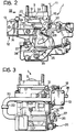
- FIGS 2, 3 show a preferred embodiment of the carburettor 1.
- the elements corresponding to those shown in Figure 1 are indicated by the same reference numerals.
- Reference numeral 25 indicates the shaft of throttle valve 3 to which an actuating lever 26 is connected.
- the lever 26 has one end supporting a spherical element 27 for connection to the usual actuating cable.
- the choke valve actuating mechanism 10 comprises a lever 28 pivoted to the fixed structure of the carburettor around an axis 29 and provided with a belt 30 for connection to the actuating cable 11.
- the actuating mechanism 10 further comprises a lever 31 mounted onto one end of the choke valve shaft 32 and carrying a follower element 33 cooperating with an arm 34 of the lever 28.
- the above-mentioned linkage mechanism connecting the choke valve actuating mechanism 10 to the throttle valve mechanism comprises a lever 35 having its ends cooperating with the lever 28 and the lever 26, respectively.
- levers 28, 26 and 35 are known per se and does not form part of the present invention.
- the actuating rod 24 connected to the diaphragm member 14 has its end opposite to the diaphragm member 14 connected to the lever 28 by means of a spherical joint 36.
- a spring 37 is interposed between the lever 28 and the rod 24 in order to take up any play which may occur between such elements.
- reference numeral 38 indicates a pipe for connection of conduit 18 to the second chamber 17 of the diaphragm device 14.
- the fuel supply system according to the present invention may be of simple and economic construction.
Landscapes
- Engineering & Computer Science (AREA)
- Chemical & Material Sciences (AREA)
- Combustion & Propulsion (AREA)
- Mechanical Engineering (AREA)
- General Engineering & Computer Science (AREA)
- Means For Warming Up And Starting Carburetors (AREA)
Description
- The present invention relates to internal combustion engines which are adapted to use alcohol as fuel during normal operating conditions and a mixture of alcohol and gasoline during starting and warming-up.
- The invention relates in particular to a fuel supply system for use in an internal combustion engine of the abovementioned type, said system comprising:
- -a carburettor, including an air passage, a float chamber and a fuel spray nozzle disposed within said air passage and connected to said float chamber,
- -an alcohol-containing main fuel tank connected to said float chamber, and
- a gasoline-containing auxiliary fuel tank connected to said carburettor.
- A fuel supply system having the above- mentioned features is disclosed in US Patent No. 1,506,229. In this known system, the gasoline-containing auxiliary fuel tank is disposed at a level higher than the carburettor and is connected to the latter by means of a conduit in which a needle valve is interposed. In order to start the engine, the attendant must operate the needle valve, causing opening of the same, so that a charge of gasoline flows by gravity from the auxiliary fuel tank to the carburettor and is mixed to the alcohol fed to the engine.
- The main drawback of this known system is that it requires the intervention of the operator in order to cause the charge of gasoline to be added to the alcohol fed to the engine during starting and warming-up.
- It is also known to provide a fuel supply system of the above described type, in which the gasoline-containing auxiliary fuel tank is connected to the air passage of the carburettor and an auxiliary pump is interposed in such connection. The auxiliary pump must be operated in order to feed gasoline from the auxiliary tank to said air passage during starting and warming-up of the engine. Thus, also this known system requires the intervention of the operator. Moreover, the operator has no control, in this case, of the amount of gasoline which is fed to the engine.
- It is also known (see FR-A-2,361,542) to provide a fuel supply system for an internal combustion engine having a kerosene-containing fuel tank, a gasoline-containing fuel tank, and a selection device for selectively connecting the fuel spray nozzle of a carburettor either to the kerosene-containing fuel tank or to the gasoline-containing fuel tank. The selector device is actuated by a diaphragm device controlled by a choke valve of the carburettor in such a manner that during starting and warming-up of the engine only gasoline is fed to the spray nozzle. Obviously, also in this case the operator has no control of the amount of gasoline which is fed to the engine.
- It is finally to be noted that US-A-2,597,776 discloses a carburettor having a connection mechanism connecting the choke valve actuating mechanism to a valve which controls the fuel flow from an auxiliary fuel tank to a float chamber.
- It is the object of the present invention to provide a fuel supply system for an internal combustion engine adapted to use alcohol as fuel, in which a very precise amount of gasoline is automatically added to the fuel fed to the engine during starting and warming-up. This object is achieved, according to the present invention, by providing a fuel supply system of the above described type, further comprising:
- - choke valve within the air passage of the carburettor, upstream of said fuel spray nozzle,
- - a choke valve actuating mechanism,
- -a gasoline supply diaphragm device, including a hollow casing and a diaphragm member within said hollow casing which defines a first chamber vented to the atmosphere, and a second chamber,
- - a first conduit connecting said second chamber to said auxiliary fuel tank,
- -a second conduit connecting said second chamber to said float chamber,
- - a first and a second one-way valves interposed in said first and second conduits respectively, preventing flow of fuel from the second chamber to the auxiliary fuel tank and from the float chamber to the second chamber,
- - a connection mechanism connecting said choke valve actuating mechanism to said diaphragm member of the gasoline supply device; said connection mechanism causing displacement of said diaphragm member towards a position in which said second chamber has a minimum volume, when said choke valve is in its operating position during starting and warming-up of the engine, whereby a precise amount of gasoline is supplied to the float chamber by the displacement of the diaphragm member.
- In the fuel supply system according to the invention, when the choke valve actuating mechanism is operated for cold starting, the above-mentioned connection mechanism causes a displacement of the diaphragm member towards a position in which said second chamber has a minimum volume, whereby a precise amount of gasoline is automatically fed from the second chamber to the alcohol containing float chamber via said second conduit. When the choke valve is returned to its non-operating position, upon warming-up of the engine, the diaphragm member returns to its normal position, whereby a new amount of gasoline is fed from the auxiliary tank to the second chamber via said first conduit.
- The foregoing and further features and advantages of the present invention will be apparent from the following more particular description, with reference to the accompanying drawings, in which:
- Figure 1 is a schematic view of the system according to the present invention, and
- Figures 2 and 3 are a front and a side view of a carburettor according to the preferred embodiment of the invention.
- In the drawings, reference No. 1 indicates a carburettor for use in an internal combustion engine which utilizes alcohol as fuel. The carburettor 1 comprises an
air passage 2, athrottle valve 3 disposed within theair passage 2 and a spray nozzle 4 disposed within theair passage 2 upstream of thethrottle valve 3. The spray nozzle 4 is connected to a float chamber 5 which is also connected by means of a conduit 6 to amain fuel tank 7, filled with alcohol. A fuel pump 8 is interposed in the conduit 6 to feed alcohol from themain fuel tank 7 to the float chamber 5. The float chamber 5 is provided with a known float mechanism (not shown) to ensure a constant level of fuel inside thereof. - The carburettor 1 further comprises a
choke valve 9 disposed in theair passage 2 upstream of the spray nozzle 4. Thechoke valve 9 is connected to a chokevalve actuating mechanism 10, including a cable 11 which can be operated against the bias of spring means (not shown) to cause displacement of thechoke valve 9 from the illustrated non-operating position to a closed operating position. - The carburettor 1 comprises a
diaphragm device 12 having ahollow casing 13 and adiaphragm member 14 which is disposed within thehollow casing 13 and defines two chambers inside thereof. Afirst chamber 15 is vented to the atmosphere through aport 16. Asecond chamber 17 is connected by afirst conduit 18 to anauxiliary fuel tank 19, filled with gasoline, and by asecond conduit 20 to the float chamber 5. Two one-way valves conduit second chamber 17 and from the latter to theauxiliary fuel tank 19. - The carburettor 1 further comprises a
connection mechanism 23 connecting the chokevalve actuating mechanism 10 to thediaphragm member 14. Theconnection mechanism 23 includes anactuating rod 24 having one end fixed to thediaphragm member 14 and the other end connected to theactuating mechanism 10. Therod 24 is slidably mounted within thehollow casing 13 of thediaphragm device 12. - During normal operation of the engine, alcohol is fed from float chamber 5 to the spray nozzle 4 and is-mixed to the air flowing through the
air passage 2. - In order to start the engine, especially in winter time, the cable 11 must be operated in order to take the
choke valve 9 to its closed operating position. A linkage mechanism connects, in a way known per se, thechoke valve 9 to thethrottle valve 3 so as to cause thethrottle valve 3 to move to a partially open position (the so-called "fast-idle" position) when thechoke valve 9 is moved to its operating position. In such a condition, therod 24 slides rightwards (with reference to Figure 1) moving thediaphragm member 14 to a position in which thesecond chamber 17 has the minimum volume. As a result of this, a precise amount (corresponding to the reduction of volume of second chamber 17) of gasoline is fed from thesecond chamber 17 to the float chamber 5 through theconduit 20 and thevalve 22. The gasoline coming fromchamber 17 is thereby mixed to the alcohol in the float chamber 5. - Preferably, the charge of gasoline is such that the alcohol-gasoline mixture comprises 95% alcohol and 5% gasoline.
- When, upon warming-up of the engine, the choke
valve actuating mechanism 10 is dis- activated, spring means (not shown) return thechoke valve 9 to its non-operating position. Thus, thediaphragm member 14 returns to the position shown in Fig. 1 and a new amount of gasoline is sucked from theauxiliary fuel tank 19 through theconduit 18 and thevalve 21. - Figures 2, 3 show a preferred embodiment of the carburettor 1. In such figures the elements corresponding to those shown in Figure 1 are indicated by the same reference numerals.
-
Reference numeral 25 indicates the shaft ofthrottle valve 3 to which an actuatinglever 26 is connected. Thelever 26 has one end supporting aspherical element 27 for connection to the usual actuating cable. The chokevalve actuating mechanism 10 comprises alever 28 pivoted to the fixed structure of the carburettor around anaxis 29 and provided with abelt 30 for connection to the actuating cable 11. Theactuating mechanism 10 further comprises alever 31 mounted onto one end of thechoke valve shaft 32 and carrying a follower element 33 cooperating with anarm 34 of thelever 28. The above-mentioned linkage mechanism connecting the chokevalve actuating mechanism 10 to the throttle valve mechanism comprises alever 35 having its ends cooperating with thelever 28 and thelever 26, respectively. - The particular structure and arrangement of
levers - The actuating
rod 24 connected to thediaphragm member 14 has its end opposite to thediaphragm member 14 connected to thelever 28 by means of aspherical joint 36. Aspring 37 is interposed between thelever 28 and therod 24 in order to take up any play which may occur between such elements. - When the cable 11 is actuated, the
lever 28 rotates counterclockwise (with reference to Fig. 2) around theaxis 29 androd 24 moves leftwards causing the charge of gasoline to be fed fromchamber 17 to the float chamber 5.Lever 35 holds thethrottle valve 3 in its "fast-idle" position when the choke valve is in its operating position. - In Figure 3
reference numeral 38 indicates a pipe for connection ofconduit 18 to thesecond chamber 17 of thediaphragm device 14. - As it would be clearly understood from the foregoing description, the fuel supply system according to the present invention may be of simple and economic construction.
Claims (2)
characterised in that said system further comprises:
Applications Claiming Priority (2)
| Application Number | Priority Date | Filing Date | Title |
|---|---|---|---|
| IT67447/80A IT1128072B (en) | 1980-03-24 | 1980-03-24 | FUEL CONTROL DEVICE FOR COLD STARTING OF AN EIGHT CYCLE ENGINE |
| IT6744780 | 1980-03-24 |
Publications (2)
| Publication Number | Publication Date |
|---|---|
| EP0036608A1 EP0036608A1 (en) | 1981-09-30 |
| EP0036608B1 true EP0036608B1 (en) | 1983-11-09 |
Family
ID=11302454
Family Applications (1)
| Application Number | Title | Priority Date | Filing Date |
|---|---|---|---|
| EP81101959A Expired EP0036608B1 (en) | 1980-03-24 | 1981-03-16 | A fuel supply system for an internal combustion engine |
Country Status (8)
| Country | Link |
|---|---|
| US (1) | US4380974A (en) |
| EP (1) | EP0036608B1 (en) |
| AR (1) | AR224567A1 (en) |
| BR (1) | BR8101715A (en) |
| DE (1) | DE3161351D1 (en) |
| IN (1) | IN153455B (en) |
| IT (1) | IT1128072B (en) |
| ZA (1) | ZA811681B (en) |
Families Citing this family (6)
| Publication number | Priority date | Publication date | Assignee | Title |
|---|---|---|---|---|
| JPS5923050A (en) * | 1982-07-30 | 1984-02-06 | Sanshin Ind Co Ltd | Starting fuel increasing device for internal-combustion engine |
| US4553504A (en) * | 1983-12-30 | 1985-11-19 | Cummins Engine Company, Inc. | Means and method for alternate fuel fumigation in internal combustion engines |
| JPS6137451U (en) * | 1984-08-10 | 1986-03-08 | 三菱自動車工業株式会社 | Auxiliary fuel supply device for alcohol engine |
| BR8801648A (en) * | 1988-04-07 | 1989-11-07 | Bosch Do Brasil | COLD STARTING SYSTEM FOR INTERNAL ALCOHOL COMBUSTION ENGINES, COLD STARTING PROCESS AND DEVICE TO BE USED IN THE SAME |
| EP0786591A3 (en) * | 1996-01-29 | 1997-08-13 | WCI OUTDOOR PRODUCTS, Inc. | Fast start fuel system for an internal combustion engine |
| US6135426A (en) * | 1998-01-07 | 2000-10-24 | Briggs And Stratton Corporation | Priming system for internal combustion engines |
Citations (8)
| Publication number | Priority date | Publication date | Assignee | Title |
|---|---|---|---|---|
| US1506229A (en) * | 1916-09-30 | 1924-08-26 | Orville H Ensign | Carburetor |
| FR856966A (en) * | 1938-06-30 | 1940-08-19 | Heavy oil carburetor for internal combustion engines | |
| FR877212A (en) * | 1940-10-15 | 1942-12-01 | Device allowing the use of alcohol-based fuel for internal combustion engines | |
| US2597776A (en) * | 1947-09-18 | 1952-05-20 | Milton E Chandler | Auxiliary fuel chamber |
| BE742916A (en) * | 1969-03-29 | 1970-05-14 | ||
| US4056087A (en) * | 1976-03-26 | 1977-11-01 | F. Travers Burgess | Two-fuel carburetor |
| FR2361542A1 (en) * | 1976-08-12 | 1978-03-10 | Fuji Heavy Ind Ltd | Carburettor for dual fuel IC engine - has two separate float chambers with mixt. regulated by suction valve and auxiliary control to correct fuel mixt. during starting |
| US4204489A (en) * | 1977-12-21 | 1980-05-27 | Toyota Jidosha Kogyo Kabushiki Kaisha | 2-Cycle engine of an active thermoatmosphere combustion type |
Family Cites Families (7)
| Publication number | Priority date | Publication date | Assignee | Title |
|---|---|---|---|---|
| US1829050A (en) * | 1928-08-18 | 1931-10-27 | Harry W Mcclure | Means for operating internal combustion engines |
| US2821183A (en) * | 1955-12-21 | 1958-01-28 | Vernon D Roosa | Fuel injection means for internal combustion engines |
| US2985159A (en) * | 1957-09-09 | 1961-05-23 | Holley Carburetor Co | Cold starting means for carburetors |
| GB1223925A (en) * | 1968-12-17 | 1971-03-03 | Zenith Carburetter Company Ltd | Improvements in or relating to fuel supply devices for cold starting of internal combustion engines |
| FR2333968A1 (en) * | 1975-12-02 | 1977-07-01 | Sibe | IMPROVEMENTS TO THE CARBURATION DEVICES FOR INTERNAL COMBUSTION ENGINES |
| US4031864A (en) * | 1976-03-09 | 1977-06-28 | The United States Of America As Represented By The United States Energy Research And Development Administration | Multiple fuel supply system for an internal combustion engine |
| US4085720A (en) * | 1976-08-11 | 1978-04-25 | Fuji Jukogyo Kabushiki Kaisha | Fuel supply system for multi-fuel internal combustion engines |
-
1980
- 1980-03-24 IT IT67447/80A patent/IT1128072B/en active
-
1981
- 1981-03-13 ZA ZA00811681A patent/ZA811681B/en unknown
- 1981-03-16 EP EP81101959A patent/EP0036608B1/en not_active Expired
- 1981-03-16 DE DE8181101959T patent/DE3161351D1/en not_active Expired
- 1981-03-23 AR AR284707A patent/AR224567A1/en active
- 1981-03-23 BR BR8101715A patent/BR8101715A/en not_active IP Right Cessation
- 1981-03-24 US US06/247,031 patent/US4380974A/en not_active Expired - Fee Related
- 1981-03-24 IN IN315/CAL/81A patent/IN153455B/en unknown
Patent Citations (8)
| Publication number | Priority date | Publication date | Assignee | Title |
|---|---|---|---|---|
| US1506229A (en) * | 1916-09-30 | 1924-08-26 | Orville H Ensign | Carburetor |
| FR856966A (en) * | 1938-06-30 | 1940-08-19 | Heavy oil carburetor for internal combustion engines | |
| FR877212A (en) * | 1940-10-15 | 1942-12-01 | Device allowing the use of alcohol-based fuel for internal combustion engines | |
| US2597776A (en) * | 1947-09-18 | 1952-05-20 | Milton E Chandler | Auxiliary fuel chamber |
| BE742916A (en) * | 1969-03-29 | 1970-05-14 | ||
| US4056087A (en) * | 1976-03-26 | 1977-11-01 | F. Travers Burgess | Two-fuel carburetor |
| FR2361542A1 (en) * | 1976-08-12 | 1978-03-10 | Fuji Heavy Ind Ltd | Carburettor for dual fuel IC engine - has two separate float chambers with mixt. regulated by suction valve and auxiliary control to correct fuel mixt. during starting |
| US4204489A (en) * | 1977-12-21 | 1980-05-27 | Toyota Jidosha Kogyo Kabushiki Kaisha | 2-Cycle engine of an active thermoatmosphere combustion type |
Also Published As
| Publication number | Publication date |
|---|---|
| ZA811681B (en) | 1982-03-31 |
| US4380974A (en) | 1983-04-26 |
| BR8101715A (en) | 1981-10-06 |
| IT1128072B (en) | 1986-05-28 |
| DE3161351D1 (en) | 1983-12-15 |
| IT8067447A0 (en) | 1980-03-24 |
| EP0036608A1 (en) | 1981-09-30 |
| IN153455B (en) | 1984-07-14 |
| AR224567A1 (en) | 1981-12-15 |
Similar Documents
| Publication | Publication Date | Title |
|---|---|---|
| US3371658A (en) | Priming method and arrangement for fuel feed system | |
| US6213083B1 (en) | Fuel shutoff system | |
| US4073278A (en) | Carburator | |
| US4056087A (en) | Two-fuel carburetor | |
| US3689036A (en) | Air-fuel mixture enriching device for constant vacuum type carburetors | |
| US4380974A (en) | Fuel supply system for an internal combustion engine | |
| US4348338A (en) | Injection-type pressure-freed carburetor | |
| CA1160919A (en) | Dual fuel supply system | |
| US2311828A (en) | Fuel control device | |
| US2985159A (en) | Cold starting means for carburetors | |
| US1932521A (en) | Outboard motor control | |
| US3103128A (en) | Engine idle speed control | |
| US2595721A (en) | Carburetor | |
| US4243002A (en) | Fuel injection system for an internal combustion engine | |
| US2653804A (en) | Fuel metering control for injection carburetors | |
| US2055539A (en) | Control mechanism for carburetors of internal combustion engines | |
| US1978660A (en) | Carburetor | |
| US1958818A (en) | Carburetor | |
| US2847021A (en) | Carburetor float valve stabilizer | |
| US2692766A (en) | Carburetor float valve control | |
| US3294375A (en) | Carburetor | |
| US3058728A (en) | Throttle-operated inside carburetor vents | |
| US4304200A (en) | Fuel injection systems for mixture compressing spark-ignition internal combustion engine | |
| JPS56121839A (en) | Fuel supply system for start-up of combustion engine | |
| US2518657A (en) | Fuel conditioning device |
Legal Events
| Date | Code | Title | Description |
|---|---|---|---|
| PUAI | Public reference made under article 153(3) epc to a published international application that has entered the european phase |
Free format text: ORIGINAL CODE: 0009012 |
|
| AK | Designated contracting states |
Designated state(s): DE FR GB |
|
| 17P | Request for examination filed |
Effective date: 19811026 |
|
| GRAA | (expected) grant |
Free format text: ORIGINAL CODE: 0009210 |
|
| AK | Designated contracting states |
Designated state(s): DE FR GB |
|
| REF | Corresponds to: |
Ref document number: 3161351 Country of ref document: DE Date of ref document: 19831215 |
|
| ET | Fr: translation filed | ||
| PLBE | No opposition filed within time limit |
Free format text: ORIGINAL CODE: 0009261 |
|
| STAA | Information on the status of an ep patent application or granted ep patent |
Free format text: STATUS: NO OPPOSITION FILED WITHIN TIME LIMIT |
|
| 26N | No opposition filed | ||
| PGFP | Annual fee paid to national office [announced via postgrant information from national office to epo] |
Ref country code: GB Payment date: 19930217 Year of fee payment: 13 |
|
| PGFP | Annual fee paid to national office [announced via postgrant information from national office to epo] |
Ref country code: DE Payment date: 19930222 Year of fee payment: 13 |
|
| PGFP | Annual fee paid to national office [announced via postgrant information from national office to epo] |
Ref country code: FR Payment date: 19930330 Year of fee payment: 13 |
|
| PG25 | Lapsed in a contracting state [announced via postgrant information from national office to epo] |
Ref country code: GB Effective date: 19940316 |
|
| GBPC | Gb: european patent ceased through non-payment of renewal fee |
Effective date: 19940316 |
|
| PG25 | Lapsed in a contracting state [announced via postgrant information from national office to epo] |
Ref country code: FR Effective date: 19941130 |
|
| PG25 | Lapsed in a contracting state [announced via postgrant information from national office to epo] |
Ref country code: DE Effective date: 19941201 |
|
| REG | Reference to a national code |
Ref country code: FR Ref legal event code: ST |