EP0035878B1 - Method and apparatus for measuring interfacial electrokinetic phenomena - Google Patents
Method and apparatus for measuring interfacial electrokinetic phenomena Download PDFInfo
- Publication number
- EP0035878B1 EP0035878B1 EP81300931A EP81300931A EP0035878B1 EP 0035878 B1 EP0035878 B1 EP 0035878B1 EP 81300931 A EP81300931 A EP 81300931A EP 81300931 A EP81300931 A EP 81300931A EP 0035878 B1 EP0035878 B1 EP 0035878B1
- Authority
- EP
- European Patent Office
- Prior art keywords
- sample
- electrodes
- pair
- current
- voltage
- Prior art date
- Legal status (The legal status is an assumption and is not a legal conclusion. Google has not performed a legal analysis and makes no representation as to the accuracy of the status listed.)
- Expired
Links
- 238000000034 method Methods 0.000 title claims description 27
- 239000002245 particle Substances 0.000 claims description 45
- 239000000523 sample Substances 0.000 description 72
- 238000005259 measurement Methods 0.000 description 35
- 230000005684 electric field Effects 0.000 description 23
- 230000005012 migration Effects 0.000 description 23
- 238000013508 migration Methods 0.000 description 23
- 238000001514 detection method Methods 0.000 description 18
- 239000011521 glass Substances 0.000 description 11
- 210000004027 cell Anatomy 0.000 description 9
- 238000001962 electrophoresis Methods 0.000 description 9
- 239000007788 liquid Substances 0.000 description 5
- NBIIXXVUZAFLBC-UHFFFAOYSA-N Phosphoric acid Chemical compound OP(O)(O)=O NBIIXXVUZAFLBC-UHFFFAOYSA-N 0.000 description 4
- 230000008859 change Effects 0.000 description 4
- 230000001276 controlling effect Effects 0.000 description 4
- 238000010586 diagram Methods 0.000 description 4
- 230000000694 effects Effects 0.000 description 4
- BASFCYQUMIYNBI-UHFFFAOYSA-N platinum Chemical compound [Pt] BASFCYQUMIYNBI-UHFFFAOYSA-N 0.000 description 4
- 238000004064 recycling Methods 0.000 description 4
- 239000012528 membrane Substances 0.000 description 3
- 238000005192 partition Methods 0.000 description 3
- 241001494479 Pecora Species 0.000 description 2
- 229910000147 aluminium phosphate Inorganic materials 0.000 description 2
- 239000007853 buffer solution Substances 0.000 description 2
- 238000005868 electrolysis reaction Methods 0.000 description 2
- 238000005370 electroosmosis Methods 0.000 description 2
- 210000003743 erythrocyte Anatomy 0.000 description 2
- 238000002474 experimental method Methods 0.000 description 2
- 239000007789 gas Substances 0.000 description 2
- 230000003287 optical effect Effects 0.000 description 2
- 229910052697 platinum Inorganic materials 0.000 description 2
- 230000001105 regulatory effect Effects 0.000 description 2
- 230000006641 stabilisation Effects 0.000 description 2
- 238000011105 stabilization Methods 0.000 description 2
- XLYOFNOQVPJJNP-UHFFFAOYSA-N water Substances O XLYOFNOQVPJJNP-UHFFFAOYSA-N 0.000 description 2
- 239000004698 Polyethylene Substances 0.000 description 1
- 230000008901 benefit Effects 0.000 description 1
- 230000033228 biological regulation Effects 0.000 description 1
- 238000006243 chemical reaction Methods 0.000 description 1
- 230000000052 comparative effect Effects 0.000 description 1
- 239000000498 cooling water Substances 0.000 description 1
- 230000003247 decreasing effect Effects 0.000 description 1
- 238000009792 diffusion process Methods 0.000 description 1
- 239000008151 electrolyte solution Substances 0.000 description 1
- 239000007924 injection Substances 0.000 description 1
- 238000002347 injection Methods 0.000 description 1
- 150000002500 ions Chemical class 0.000 description 1
- 239000007791 liquid phase Substances 0.000 description 1
- 238000013208 measuring procedure Methods 0.000 description 1
- 239000011859 microparticle Substances 0.000 description 1
- 238000012544 monitoring process Methods 0.000 description 1
- 239000002504 physiological saline solution Substances 0.000 description 1
- -1 polyethylene Polymers 0.000 description 1
- 229920000573 polyethylene Polymers 0.000 description 1
- 230000008569 process Effects 0.000 description 1
- 239000010453 quartz Substances 0.000 description 1
- 230000009467 reduction Effects 0.000 description 1
- 230000004044 response Effects 0.000 description 1
- 238000000926 separation method Methods 0.000 description 1
- VYPSYNLAJGMNEJ-UHFFFAOYSA-N silicon dioxide Inorganic materials O=[Si]=O VYPSYNLAJGMNEJ-UHFFFAOYSA-N 0.000 description 1
- 239000000243 solution Substances 0.000 description 1
- 239000002904 solvent Substances 0.000 description 1
- 238000004804 winding Methods 0.000 description 1
Images




Classifications
-
- G—PHYSICS
- G01—MEASURING; TESTING
- G01N—INVESTIGATING OR ANALYSING MATERIALS BY DETERMINING THEIR CHEMICAL OR PHYSICAL PROPERTIES
- G01N27/00—Investigating or analysing materials by the use of electric, electrochemical, or magnetic means
- G01N27/26—Investigating or analysing materials by the use of electric, electrochemical, or magnetic means by investigating electrochemical variables; by using electrolysis or electrophoresis
- G01N27/416—Systems
- G01N27/447—Systems using electrophoresis
- G01N27/44704—Details; Accessories
- G01N27/44713—Particularly adapted electric power supply
-
- G—PHYSICS
- G01—MEASURING; TESTING
- G01N—INVESTIGATING OR ANALYSING MATERIALS BY DETERMINING THEIR CHEMICAL OR PHYSICAL PROPERTIES
- G01N27/00—Investigating or analysing materials by the use of electric, electrochemical, or magnetic means
- G01N27/26—Investigating or analysing materials by the use of electric, electrochemical, or magnetic means by investigating electrochemical variables; by using electrolysis or electrophoresis
- G01N27/416—Systems
- G01N27/447—Systems using electrophoresis
Definitions
- This invention relates to a method and apparatus for observing and measuring interfacial electrokinetic phenomena such as electrophoresis and electro-osmosis. More specifically, this invention relates to the measurement of the electro-osmotic phenomenon, that is, the measurement of the fluidity of liquid resulting from the movement of the solvent accompanying the migration of ions in which the diffusion double layer in the case where an electric field is applied along a solid-liquid interfaces or a liquid- liquid interface, or for the measurement of the moving speed of electric charged particles in an electric field.
- an electrophoretic apparatus for observing the movement of charged particles has been well known in the field of art concerning micro particles having surface charge.
- a stationary electric field is produced in a migration chamber (electrophoresis cell) by applying a constant voltage between a pair of electrodes disposed in the migration chamber and the charged particles in the chamber are moved in accordance with the electric field.
- the moving speed of the particles is observed and measured by means of a microscope coupled with an optical source.
- the electrophoretic mobility obtained through measurement of the electrophoretic apparatus is represented by the speed of each of the particles per intensity of the electric field (pm/s per V/cm). It is, accordingly, significant for the measurement of the electrophoretic phenomena to supply an essentially constant electric field to a sample to be measured and to hold a sample at the constant temperature in order to obtain highly accurate measured values, and this is an important problem.
- a constant current power source rather than a constant voltage power source for the measurement of electrophoretic mobility.
- the intensity of the electric field is determined by calculation as the product of the current and the electrical resistance of the sample per unit distance.
- the measurement under the condition of constant temperature is also indispensable in this case.
- US-A-3 454 487 is representative of the state of the art as above described.
- the time in which the particle flow is stabilized in the procedure described in paragraph 4 is about 0.1 - 0.2 s.
- the temperature of the sample in the measuring cell is raised by the Joule's heat generated by the supply of the measuring DC and generally it takes from ten up to several hundreds of seconds depending on the cell structure to stabilize the temperature of the sample. Accordingly, although the actual measuring time for the mobility is within 1-3 s for each step, the time necessary for one measurement step is from ten to several hundreds of seconds if the measurement is to be started after settling of the temperature, which is time consuming.
- the particles to be measured continue to move in one direction while waiting for the stabilization of the temperature under the supply of the measuring DC, and most of the particles get out of view when the particles move in one direction in the electrophoretic measuring method using a microscope. Thus, it has been impossible to conduct measurement at high accuracy under constant temperature.
- An object of this invention is to obtain measured values at high accuracy under the condition of constant temperature.
- a method of observing electrophoretic phenomena of charged particles in a sample such method being characterized by the steps of preheating the sample by supplying an alternative current to the sample, the frequency of the alternating current being high enough to keep the charged particles in the sample substantially stationary; and supplying a direct current to the thus preheated sample so as to observe the electrophoretic phenomena, and maintaining the electric power dissipated in the sample due to the direct current substantially equal to the electric power dissipated in the sample due to the alternating current.
- the invention also provides apparatus for observing electrophoretic phenomena of charged particles in a sample comprising a chamber for accommodating the sample, the chamber having a pair of electrodes; and an electric power supply system for supplying current to the sample through said pair of electrodes, characterized in that the electric power supply system has an alternating-current power supply for delivering the alternating current so as to preheat the sample, a direct current power supply for delivering the direct current so as to observe ths electrophoretic phenomena, and an output selection circuit for selectively supplying either the alternating or direct current to the sample through said pair of electrodes, the system being such that in use the alternating current has a frequency high enough to keep the charged particles in the sample substantially stationary, and a magnitude such that the electric power dissipated in the sample due to the alternating current is substantially equal to that dissipated in the sample due to the direct-current.
- the invention makes it possible to keep the temperature of a sample to be measured constant upon measurement of the mobility of the particles, by continuously supplying an AC to the sample while DC for the measurement of the electrophoresis is not being supplied to the sample.
- AC electric power is consumed in the sample at the same rate as is electric power consumed by the measuring DC.
- the AC is of such a frequency that the particles can be regarded as being in a stationary state in view of the easy determination of the particles to be measured, and preferably the frequency is more than 10 Hz.
- the voltage between two points at positions other than the electrode for the voltage application in the sample is measured, and used to control the current so as to always make the detected voltage constant.
- the voltage between the voltage detection probes is fed back to the power source system through terminals connected to the detection probes.
- the intensity of the electric field can thus be made constant following changes in the electrical resistance of the sample to be measured to thereby render the electric field intensity constant and improve the measuring accuracy significantly.
- This invention can be applied not only to the measurement of the electrophoresis using a microscope type apparatus but also to the measurment of electrophoretic phenomena or the measurement of electro-osmosis using a detector based on the doppler method.
- the method and apparatus for measuring the interfacial electrokinetic phenomena according to this invention can be used to obtain measured values at high accuracy by the application of an essentially constant voltage to a sample to be measured with no effects from the Joule's heat generated by supplied current and the like.
- the electrophoretic measuring apparatus which is a first embodiment of this invention is placed in a temperature constant bath 1, and comprises a U-shaped glass tube 2 constituting a migration chamber, a pair of electrodes 30, 31 disposed with 50 mm gap to each other at the bottom of the U-shaped glass tube 2 and a power source 7 for supplying electrical current to the electrodes 30, 31.
- the U-shaped glass tube 2 is of 2 mm inner diameter and filled with a sample 21 to be measured.
- a sheathed thermocouple 32 of 0.25 mm outer diameter covered with a polyethylene tube is disposed about in the middle of the inside of the glass tube and connected to a temperature indicator (thermometer) 33 for monitoring the temperature in the U-shaped glass tube 2.
- the power source system 7 comprises a reactangular waveform generator (oscillator) A, a power controller or regulator B, an output selection circuit C and a rectifier circuit D.
- the power source system is constituted such that the rectangular waveform produced from the rectangular waveform generator A is regulated by the power regulator B, passed through the rectifier circuit D depending on the indication from the output selection circuit C which determines either to convert the output into DC or supply it as AC and then supplied byway of the electrodes 30, 31 for applying an electric field to the sample 21.
- the power source 7 After setting the sample 21 in such a measuring apparatus, the power source 7 is put to ON to apply the electric field.
- the output selection circuit C of the power source system 7 is designed such that the AC is at first supplied to the sample 21 for a predetermined of time and then the DC is supplied to the sample 21. The mobility of the particles in the sample is measured during supply of the DC.
- the power source may be composed of an AC power source A 1 and a DC power source A 2 , instead of the generator A in Fig. 2, and each of the power sources may be connected by way of output regulation circuits (power regulator) 8 1 , B 2 to an output selection circuit C.
- output regulation circuits power regulator
- the mobility can be measured at a constant temperature by the use of the measuring method and apparatus according to this invention, generation of errors resulted from the temperature change is prevented and the measuring accuracy can be improved significantly.
- Fig. 4 shows an electrophoretic measuring apparatus using another embodiment of the power source system 7.
- the power source system 7 shown in Fig. 4 comprises a constant current DC power source 71 rated at 10 mA for applying, to the sample, an electric field causing electrophoresis and a variable transformer 73 connected to an AC power source 72 of commercial frequency and having an AC voltmeter 74 for the output measurement, which are connected to each other in parallel by way of an output switching or conversion circuit 17.
- the power from the power source system 7 is supplied by way of output terminals 9, 11 to the electrodes 30, 31.
- the output switching circuit 17 comprises a positive DC relay switch 18 that is connected to apply a positive DC voltage to the electrodes 30, 31 when closed and a negative DC relay switch 19 that is connected to apply a negative DC voltage to the electrodes 30, 31 when closed.
- the output switching circuit 17 is constituted such that the electrodes 30, 31 are connected by way of the variable transformer 73 to the AC power source 72 when both of the relay switches 18, 19 are opened.
- the temperature constant bath 1 is set to 20°C ⁇ 0.1°C by a temperature control device or thermocontroller 4 and a heater 15.
- the U-shaped glass tube 2 filled with physiological saline water as a sample is placed in the temperature constant bath 1. Then, the AC power source 72 is put to ON and AC is supplied to the current supply electrodes 30, 31 for about 10 min. while regulating the output by the variable transformer 73 so that the volt meter 74 indicates 108 V. (Both of the positive DC relay switch 18 and the negative DC relay switch 19 are kept OFF.)
- the positive DC relay switch 18 is turned ON thereby switching the current supply from AC to DC.
- the temperature in the U-shaped glass tube 2 shown by the temperature indicator 33 changes only within a range of 0.1°C upon switching from AC to DC and the temperature is also kept at a constant level after the switching.
- a particle to be measured is determined during supply of the AC where the particles are in a stationary state and, when the temperature in the sample to be measured is well-stabilized, the positive DC relay switch 18 is put ON to measure the moving speed of the particle. Then, the negative DC relay switch 19 is put ON to measure the moving speed of the particle in the opposite direction.
- the mobility of one particle is determined as the average value for the moving speeds in the positive and the negative directions. Thereafter, another particles to be measured are selected and measurements are repeated against from several tens to several hundreds of particles both for the positive and the negative directions and the mobility is determined from the average value obtained therefrom.
- the electrophoretic measuring apparatus comprises a square type measuring cell 20 of 0.7 mm depth and 7 mm height having at its outside a recycling bath 10 for cooling water, current supply electrodes 30, 31 disposed on respective ends and a power source system (P.S.) 80 for supplying power to them.
- P.S. power source system
- the recycling bath 10 is set to a temperature of 20°C ⁇ 0.1°C by water pipe 24 for recycling and motor 23 a temperature control device (T.C.) 4 and a heater 15.
- the cell 20 is filled with culture solution "EAGLE” (registered trade mark) containing sheep red blood cells floating therein as the sample to be measured.
- Voltage detection electrodes (probes) 50, 51 are disposed in the inside of the current supply electrodes 30, 31 for the measurement of voltage by the DC volt meter (V.M.) 40 connected thereto.
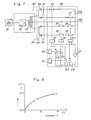
- the power source system 80 comprises, as shown in Fig. 7, a rectangular waveform generator 81, an amplifier 82 for amplifying rectangular waveform signals from the generator 81, a pulse transformer 83 for stepping-up the rectangular voltage from the amplifier 82, a group of rectifiers 84 for rectifying the alternative rectangular power from the transformer 83 and a control circuit 85, the rectifier group 84 having diodes 86 to 89.
- the control circuit 85 comprises a relay switch 90 for positive DC indication, a relay switch 91 for negative DC indication, a relay 93 having a normally closed contact 92, a relay 96 having normally opened contacts 94, 95, and a relay 100 having normally closed contacts 97, 98 and normally opened contact 99, in which voltage from a AC power source 101 is applied to the relays 93, 96 and 100.
- the relay switches 90, 91 have normally opened contacts 102, 103, 104 and 105 respectively for controlling the current supplied from the AC power source 101 to the relays 93, 96, 100.
- output terminals 107, 108 are connected to the current supply electrodes 30, 31 in which the output terminal 108 is directly led out from the center tap in the secondary windings of the transformer 83 and the output terminal 107 is connected to the output of the control circuit.
- the amplifier 82 is designed such that the amplifying factor can optionally be adjusted from the outside.
- the temperature change can be kept within the range of 0.1°C and the voltage fluctuation can be kept less than 0.5 V upon AC and DC switching, and the temperature and the voltage are also kept constant with no changes thereafter.
- the voltage which was at 71.5 V at the start of the supply goes 70 V and the temperature changes as shown in Fig. 8, in which the ordinate indicates the temperature T (°C) and abscissa indicates the time t (s).
- FIG. 9 Another embodiment of the power source system 7 for use with this invention is to be explained referring to Fig. 9, in which the system is adapted such that AC input (source) 41 is rectified through a rectifier circuit 42 into a DC and outputted through a driver 44 as current output under the control of the information set to a voltage generator 43. The output is applied to the electrodes 30, 31 of the electrophoretic apparatus on the load. While on the other hand, the voltage between the voltage detection probes are fed back by way of terminals of the power source system connected to the voltage detection probes 50, 51 disposed in the migration chamber to the power source system. The feed back voltage is amplified in a high input impedance amplifier 45.
- the amplified voltage Va is compared in a comparison circuit (comparator) 46 with a voltage Vb set to a voltage generator 43 by a voltage setter 47 consisting, for example, of a potentiometer and the comparison result is outputted to the driver 44, so that the output current from the driver 44 is controlled in the direction of decreasing the current where Va is greater than Vb and in the direction of increasing the current where Va is smaller than Vb to thereby maintain the voltage constant between the voltage detection probes.
- the intensity of the electric field can thus be kept constant also following after the changes of the electrical resistance of the liquid. Further, direct control for the intensity of the electric field in the migration chamber is also possible to thereby improve the accuracy in the measurement of the electrophoretic mobility.
- partition means such as separation membranes can be provided between the migration chamber and the electrode so that the effect of the gases on the electrophoresis generated due to electrolysis at the electrodes can be eliminated.
- the apparatus of this invention can measure the sample irrespective of the impedance, if it is high, between the electrode and the sample or the sample of extremely high resistance, by using small-sized voltage detection probes 50, 51 such as made of platinum in the migration chamber of the electrophoretic apparatus and setting the input impedance of the amplifier circuit connected to the voltage detection probes 50, 51 extremely high, for example, greater than 10' ⁇ .
- the apparatus mainly comprises a migration chamber 20 disposed in a temperature constant bath 1 and electrodes 30, 31 connected on both ends of the migration chamber 20 for supplying current from the power source system 7 to the migration chamber 20.
- the constant temperature bath 1 is equipped with a temperature control device 4 and adapted to keep the temperature constant in the migration chamber 20.
- the migration chamber 20 made of a cylindrical quartz of in 7 mm x 0.5 mm cross section and 80 mm length has at its both ends glass tubes each having a sample injection port 5 and a sample discharge port 6 respectively.
- Each of the opening ends of the glass tubes is connected by way of a gasket 14 and a partition membrane 13 to an electrolytic solution tank 12 containing phosphoric acid buffer solution and having electrodes 30, 31.
- the partition membrane 13 functions to prevent the effects of the gas on the electrophoresis generated upon electrolysis at the electrodes 30, 31.
- the power source system 7 comprises a DC power source 71 designed to set a voltage Vb and a pair of platinum voltage detection probes 50, 51 disposed in the flow passage of the migration chamber 20.
- 8 is a thermometer. It further comprises a device for controlling the current supplied from the DC power source 71 to the electrodes 30, 31 so that decrease the current where Va is greater than Vb and increase the current where Va is smaller than Vb so that the voltage Va between the voltage detection probes is fed back to make the voltage constant and a polarity invert (converter) 16 for carrying out the measurement of the electrophoresis both under the positive and the negative polarities.
- the migration chamber 20 is placed in a constant temperature bath 1 having the temperature control device 4 and kept at a constant temperature.
- the sample is supplied to the migration chamber 20 by the opening and closure of the sample charge port 5 and the discharge port 6 that can automatically be opened and closed and, when the temperature of the sample is stabilized, a DC is supplied to the electrodes 30, 31 from the power source 7 so that the voltage between the voltage detection probes 50, 51 is constant.
- the DC power source 71 is constituted to be operated under the AC 100 V input and to output maximum 20 mA and 200 V.
- Signals from the voltage detection probes 50, 51 are inputted into a polarity converter 16 so as to control its polarity and then put into the comparative controlling circuit (not shown) in power source unit 7.
- the comparative controlling circuit (not shown) in power source unit 7.
- output from DC power source 71 is controlled, and then the output is applied into electrodes 30, 31 through the polarity converter.
- Ths sample in the migration chamber 20 is moved by the electric field applied between the electrodes 30, 31 and the mobility based on the moving speed under the positive and negative electric fields is measured microscopically using an optical source.
- the microscope (not shown) is located at such a position that the movement of the particles in the migration chamber 20 can be observed.
- Fig. 11 Electrical gradient in the migration chamber is shown in Fig. 11. Since current is controlled depending on the voltage Va between the voltage detection probes in this apparatus, compensation is made for the voltage drop V, + V 2 between the electrodes 30, 31 and the sample to be measured. Mobility for each of the particles is determined by the average value for the mobility of each of the particles in the positive and negative electric fields.
- Mobility of 0.93 (um/s)/(V/cm) (average value for 50 samples) was obtained as the result of the electrophoretic measurement.
- the voltage Va between the voltage detection probes could be kept within 70 V ⁇ 0.5 V and the error due to the voltage fluctuation could be restricted below ⁇ 0.7 % during the above measurement. Since the voltage fluctuation was 67.5 - 70.0 V and the error was ⁇ 2 % in the measurement using the electrophoretic apparatus of constant current system under the same conditions, the advantageous effects of this invention is apparent.
- the electrophoretic measuring apparatus additionally comprises a control circuit 200 that determines the amplifying factor of the amplifier 82 shown in the second embodiment by sensing the detection voltage between the voltage detection probes 50, 51 instead of controlling the amplifying factor externally.
- the control circuit 200 comprises a voltage setter 36 to which a reference voltage can be set externally, and a controller (comparator) 35 which compares the voltage set by the setter 36 with the detection voltage to control the gain of amplifier 82 so as to make the difference to zero.
- the same experiment as that with second embodiment was carried out using this apparatus. As the result, the voltage fluctuation could be kept within 0.3 V.
- This apparatus enables measurement at high accuracy under a constant temperature and an essentially constant electric field.
Landscapes
- Health & Medical Sciences (AREA)
- Life Sciences & Earth Sciences (AREA)
- Molecular Biology (AREA)
- Chemical & Material Sciences (AREA)
- Chemical Kinetics & Catalysis (AREA)
- Electrochemistry (AREA)
- Physics & Mathematics (AREA)
- Analytical Chemistry (AREA)
- Biochemistry (AREA)
- General Health & Medical Sciences (AREA)
- General Physics & Mathematics (AREA)
- Immunology (AREA)
- Pathology (AREA)
- Engineering & Computer Science (AREA)
- Power Engineering (AREA)
- Investigating Or Analysing Biological Materials (AREA)
- Investigating Or Analyzing Materials By The Use Of Electric Means (AREA)
Description
- This invention relates to a method and apparatus for observing and measuring interfacial electrokinetic phenomena such as electrophoresis and electro-osmosis. More specifically, this invention relates to the measurement of the electro-osmotic phenomenon, that is, the measurement of the fluidity of liquid resulting from the movement of the solvent accompanying the migration of ions in which the diffusion double layer in the case where an electric field is applied along a solid-liquid interfaces or a liquid- liquid interface, or for the measurement of the moving speed of electric charged particles in an electric field.
- As apparatus for measuring interfacial electrokinetic phenomena, an electrophoretic apparatus for observing the movement of charged particles has been well known in the field of art concerning micro particles having surface charge.
- In this electrophoretic apparatus, a stationary electric field is produced in a migration chamber (electrophoresis cell) by applying a constant voltage between a pair of electrodes disposed in the migration chamber and the charged particles in the chamber are moved in accordance with the electric field. For example, the moving speed of the particles is observed and measured by means of a microscope coupled with an optical source. The electrophoretic mobility obtained through measurement of the electrophoretic apparatus is represented by the speed of each of the particles per intensity of the electric field (pm/s per V/cm). It is, accordingly, significant for the measurement of the electrophoretic phenomena to supply an essentially constant electric field to a sample to be measured and to hold a sample at the constant temperature in order to obtain highly accurate measured values, and this is an important problem.
- Since potential difference often exists between the two electrodes even if no electric field is applied externally, the current flowing in a sample is frequently different depending on the direction of the electric field.
- Consequently, in a case where a constant voltage power source is employed, for example, as the power source for the application of the electric field, although the voltage between a pair of electrodes in the electrophoretic apparatus can be kept constant, the potential gradient (gradient in the electric field intensity) in the migration chamber, for example, the voltage drop resulting between the sample to be measured and electrode, is not always constant. Thus, since the voltage applied to the sample itself is not actually constant, accurate measuring values cannot be obtained.
- Accordingly, it is generally preferred to use a constant current power source rather than a constant voltage power source for the measurement of electrophoretic mobility. The intensity of the electric field is determined by calculation as the product of the current and the electrical resistance of the sample per unit distance. The measurement under the condition of constant temperature is also indispensable in this case.
- In order to make the temperature constant in the migration chamber, means for recycling heat medium to the outside of a measuring cell that forms a migration chamber and keeping the temperature of the medium constant is generally employed. However, this measure still involves such disadvantages as that no rapid response is possible for the generation of Joule's heat in the sample to be measured caused by the DC (direct current) for the application of the electric field. Thus, the foregoing problems cannot yet be solved.
- US-A-3 454 487 is representative of the state of the art as above described.
- The fundamental operational procedures to measure the electrophoretic mobility are as follow:-
- 1. A sample to be measured is introduced into a measured cell.
- 2. When the fluctuation of particles in the sample in the measuring cell is settled, the sample is microscopically observed to determine a particle to be measured.
- 3. DC is supplied to start the flow of the particle.
- 4. When the flow of the particle is settled to a stationary state after the application of the DC, the mobility of the particle, that is, the moving distance per unit time, is measured.
- 5. After completion of the measurement, the polarity of the DC is reversed and the same procedures as those in
paragraphs 3 and 4 above are conducted to measure the mobility of the particle in the opposite direction. - 6. The average value for the mobility as measured in
paragraphs - The procedures described in paragraphs 2 to 6 are repeated for from several tens to several hundreds of particles and the average value obtained therefrom is determined as the average mobility for the particles in the sample.
- The time in which the particle flow is stabilized in the procedure described in
paragraph 4 is about 0.1 - 0.2 s. However, the temperature of the sample in the measuring cell is raised by the Joule's heat generated by the supply of the measuring DC and generally it takes from ten up to several hundreds of seconds depending on the cell structure to stabilize the temperature of the sample. Accordingly, although the actual measuring time for the mobility is within 1-3 s for each step, the time necessary for one measurement step is from ten to several hundreds of seconds if the measurement is to be started after settling of the temperature, which is time consuming. Further, the particles to be measured continue to move in one direction while waiting for the stabilization of the temperature under the supply of the measuring DC, and most of the particles get out of view when the particles move in one direction in the electrophoretic measuring method using a microscope. Thus, it has been impossible to conduct measurement at high accuracy under constant temperature. - An object of this invention is to obtain measured values at high accuracy under the condition of constant temperature.
- According to the present invention, there is provided a method of observing electrophoretic phenomena of charged particles in a sample, such method being characterized by the steps of preheating the sample by supplying an alternative current to the sample, the frequency of the alternating current being high enough to keep the charged particles in the sample substantially stationary; and supplying a direct current to the thus preheated sample so as to observe the electrophoretic phenomena, and maintaining the electric power dissipated in the sample due to the direct current substantially equal to the electric power dissipated in the sample due to the alternating current.
- The invention also provides apparatus for observing electrophoretic phenomena of charged particles in a sample comprising a chamber for accommodating the sample, the chamber having a pair of electrodes; and an electric power supply system for supplying current to the sample through said pair of electrodes, characterized in that the electric power supply system has an alternating-current power supply for delivering the alternating current so as to preheat the sample, a direct current power supply for delivering the direct current so as to observe ths electrophoretic phenomena, and an output selection circuit for selectively supplying either the alternating or direct current to the sample through said pair of electrodes, the system being such that in use the alternating current has a frequency high enough to keep the charged particles in the sample substantially stationary, and a magnitude such that the electric power dissipated in the sample due to the alternating current is substantially equal to that dissipated in the sample due to the direct-current.
- With the invention accuracy can be improved and a shorter time is required for measurement.
- The invention makes it possible to keep the temperature of a sample to be measured constant upon measurement of the mobility of the particles, by continuously supplying an AC to the sample while DC for the measurement of the electrophoresis is not being supplied to the sample. In the interval between the successive measurement steps AC electric power is consumed in the sample at the same rate as is electric power consumed by the measuring DC. The AC is of such a frequency that the particles can be regarded as being in a stationary state in view of the easy determination of the particles to be measured, and preferably the frequency is more than 10 Hz.
- Preferably, the voltage between two points at positions other than the electrode for the voltage application in the sample is measured, and used to control the current so as to always make the detected voltage constant. The voltage between the voltage detection probes is fed back to the power source system through terminals connected to the detection probes. The intensity of the electric field can thus be made constant following changes in the electrical resistance of the sample to be measured to thereby render the electric field intensity constant and improve the measuring accuracy significantly.
- This invention can be applied not only to the measurement of the electrophoresis using a microscope type apparatus but also to the measurment of electrophoretic phenomena or the measurement of electro-osmosis using a detector based on the doppler method. The method and apparatus for measuring the interfacial electrokinetic phenomena according to this invention can be used to obtain measured values at high accuracy by the application of an essentially constant voltage to a sample to be measured with no effects from the Joule's heat generated by supplied current and the like.
- This invention will be more clearly understood from the following description given by way of example only, with reference to the accompanying drawings, in which:
- Fig. 1 is a schematic view of an electrophoretic measuring apparatus as a first embodiment according to this invention;
- Fig. 2 and Fig. 3 are block diagrams for another power source systems for use with this invention;
- Fig. 4 is a circuit diagram for the power source system used in the apparatus shown in Fig. 1;
- Fig. 5 is a chart showing temperature changes. in a U-shaped glass tube in a conventional measuring apparatus;
- Fig. 6 is a schematic view of an electrophoretic measuring apparatus as a second embodiment according to this invention;
- Fig. 7 is a circuit diagram for the power source system used in the apparatus shown in Fig. 6;
- Fig. 8 is a chart showing temperature change in a measuring cell in a conventional measuring apparatus;
- Fig. 9 is a block diagram showing another power source system for use with this invention;
- Fig. 10 is a schematic view of an electrophoretic measuring apparatus as a third embodiment using the power source shown in Fig. 9;
- Fig. 11 is a characteristic graph showing the voltage distribution in each of the sections of the power source system for use with this invention; and
- Fig. 12 is a schematic view of an electrophoretic measuring apparatus as a fourth embodiment according to this invention.
- As shown in Fig. 1, the electrophoretic measuring apparatus which is a first embodiment of this invention is placed in a temperature constant bath 1, and comprises a U-shaped glass tube 2 constituting a migration chamber, a pair of
electrodes power source 7 for supplying electrical current to theelectrodes - The U-shaped glass tube 2 is of 2 mm inner diameter and filled with a
sample 21 to be measured. Asheathed thermocouple 32 of 0.25 mm outer diameter covered with a polyethylene tube is disposed about in the middle of the inside of the glass tube and connected to a temperature indicator (thermometer) 33 for monitoring the temperature in the U-shaped glass tube 2. - As shown in Fig. 2, the
power source system 7 comprises a reactangular waveform generator (oscillator) A, a power controller or regulator B, an output selection circuit C and a rectifier circuit D. The power source system is constituted such that the rectangular waveform produced from the rectangular waveform generator A is regulated by the power regulator B, passed through the rectifier circuit D depending on the indication from the output selection circuit C which determines either to convert the output into DC or supply it as AC and then supplied byway of theelectrodes sample 21. - After setting the
sample 21 in such a measuring apparatus, thepower source 7 is put to ON to apply the electric field. The output selection circuit C of thepower source system 7 is designed such that the AC is at first supplied to thesample 21 for a predetermined of time and then the DC is supplied to thesample 21. The mobility of the particles in the sample is measured during supply of the DC. - As shown in Fig. 3, the power source may be composed of an AC power source A1 and a DC power source A2, instead of the generator A in Fig. 2, and each of the power sources may be connected by way of output regulation circuits (power regulator) 81, B2 to an output selection circuit C.
- Since the mobility can be measured at a constant temperature by the use of the measuring method and apparatus according to this invention, generation of errors resulted from the temperature change is prevented and the measuring accuracy can be improved significantly.
- Further, since repeated measurements usually required can be performed by repeating the procedures of determining particles to be measured under the AC application state, switching the AC directly to the DC and measuring the mobility of the particles, time for the stabilization of temperature is no more necessary as in conventional apparatus and the measuring time can be shortened remarkably. The rectangular waveform generator can be substituted with commercial AC power source.
- Fig. 4 shows an electrophoretic measuring apparatus using another embodiment of the
power source system 7. - The
power source system 7 shown in Fig. 4 comprises a constant currentDC power source 71 rated at 10 mA for applying, to the sample, an electric field causing electrophoresis and avariable transformer 73 connected to an AC power source 72 of commercial frequency and having anAC voltmeter 74 for the output measurement, which are connected to each other in parallel by way of an output switching orconversion circuit 17. The power from thepower source system 7 is supplied by way ofoutput terminals 9, 11 to theelectrodes output switching circuit 17 comprises a positiveDC relay switch 18 that is connected to apply a positive DC voltage to theelectrodes DC relay switch 19 that is connected to apply a negative DC voltage to theelectrodes output switching circuit 17 is constituted such that theelectrodes variable transformer 73 to the AC power source 72 when both of the relay switches 18, 19 are opened. In the apparatus shown by Fig. 1, the temperature constant bath 1 is set to 20°C ± 0.1°C by a temperature control device orthermocontroller 4 and aheater 15. - Experimental measurement 1 using the electrophoretic or thermocontroller measuring apparatus having the power source system shown in Fig. 4 is explained.
- The U-shaped glass tube 2 filled with physiological saline water as a sample is placed in the temperature constant bath 1. Then, the AC power source 72 is put to ON and AC is supplied to the
current supply electrodes variable transformer 73 so that thevolt meter 74 indicates 108 V. (Both of the positiveDC relay switch 18 and the negativeDC relay switch 19 are kept OFF.) - After the values indicated on the
temperature indicator 33 is settled to attain the stabilized state, the positiveDC relay switch 18 is turned ON thereby switching the current supply from AC to DC. - As the result of this procedure we can keep the good condition shown in the following.
- The temperature in the U-shaped glass tube 2 shown by the
temperature indicator 33 changes only within a range of 0.1°C upon switching from AC to DC and the temperature is also kept at a constant level after the switching. - For the reference, the temperature change with time in the U-shaped glass tube of a conventional apparatus where the DC is supplied to the electrodes only during measurement is shown in Fig. 5, in which ordinate indicates the temperature T(°C) and abscissa indicates the time t (s).
- It is apparent also by reference to Fig. 5 that by the use of the apparatus and the method of this invention measurement can be performed under a constant temperature condition, whereby the measuring accuracy can significantly be improved.
- In the actual measurement of the particle mobility, the following procedures are taken. A particle to be measured is determined during supply of the AC where the particles are in a stationary state and, when the temperature in the sample to be measured is well-stabilized, the positive
DC relay switch 18 is put ON to measure the moving speed of the particle. Then, the negativeDC relay switch 19 is put ON to measure the moving speed of the particle in the opposite direction. The mobility of one particle is determined as the average value for the moving speeds in the positive and the negative directions. Thereafter, another particles to be measured are selected and measurements are repeated against from several tens to several hundreds of particles both for the positive and the negative directions and the mobility is determined from the average value obtained therefrom. - The apparatus and the method for measuring electrophoresis in the second embodiment of this invention is explained referring to Fig. 6 and Fig. 7.
- The electrophoretic measuring apparatus comprises a square
type measuring cell 20 of 0.7 mm depth and 7 mm height having at its outside arecycling bath 10 for cooling water,current supply electrodes - The
recycling bath 10 is set to a temperature of 20°C ± 0.1°C bywater pipe 24 for recycling and motor 23 a temperature control device (T.C.) 4 and aheater 15. - The
cell 20 is filled with culture solution "EAGLE" (registered trade mark) containing sheep red blood cells floating therein as the sample to be measured. Voltage detection electrodes (probes) 50, 51 are disposed in the inside of thecurrent supply electrodes rectangular waveform generator 81, anamplifier 82 for amplifying rectangular waveform signals from thegenerator 81, apulse transformer 83 for stepping-up the rectangular voltage from theamplifier 82, a group ofrectifiers 84 for rectifying the alternative rectangular power from thetransformer 83 and acontrol circuit 85, therectifier group 84 having diodes 86 to 89. Thecontrol circuit 85 comprises arelay switch 90 for positive DC indication, a relay switch 91 for negative DC indication, arelay 93 having a normally closedcontact 92, arelay 96 having normally openedcontacts relay 100 having normally closedcontacts contact 99, in which voltage from aAC power source 101 is applied to therelays contacts AC power source 101 to therelays - In the power source system 80,
output terminals 107, 108 are connected to thecurrent supply electrodes transformer 83 and theoutput terminal 107 is connected to the output of the control circuit. Theamplifier 82 is designed such that the amplifying factor can optionally be adjusted from the outside. - When none of the relay switches 90 and 91 is actuated since none of the
relays diodes output terminals 107, 108 and applied to thecurrent supply electrodes - When the positive
DC relay switch 90 is actuated by a sequence circuit (not shown), since thecontacts relays contact 92 and turns ON thecontacts diodes 87, 89 alternately and a DC voltage is outputted to theoutput terminals 107, 108 and a positive DC voltage is applied to thecurrent supply electrodes - In the opposite case where the negative DC relay switch 91 is actuated by the sequence circuit (not shown), since the
contacts relays contacts contacts diodes 86, 88 alternately in the direction opposite to the previous case. Thus a DC voltage is outputted to theoutput terminals 107, 108 and a negative DC voltage is applied to thecurrent supply electrodes - The procedures for the electrophoric measurement using said measuring apparatus are conducted in the same manner as previously explained for the first embodiment, in which the sequence circuit (not shown) supplies the operation voltage for the
positive relay switch 90 and the negative relay switch 91 to proceed the supplying process for AC and DC (positive and negative polarities). - In the use of the above-mentioned power source system, the temperature change can be kept within the range of 0.1°C and the voltage fluctuation can be kept less than 0.5 V upon AC and DC switching, and the temperature and the voltage are also kept constant with no changes thereafter. In a case where 10 mA DC is supplied only during measurement in a conventional power source system, the voltage which was at 71.5 V at the start of the supply goes 70 V and the temperature changes as shown in Fig. 8, in which the ordinate indicates the temperature T (°C) and abscissa indicates the time t (s). As apparent from the result of the measurement, according to the measuring method of this invention using such an apparatus, measurement can be performed with excellently high accuracy in a short time under the stabilized temperature. i
- Another embodiment of the
power source system 7 for use with this invention is to be explained referring to Fig. 9, in which the system is adapted such that AC input (source) 41 is rectified through arectifier circuit 42 into a DC and outputted through adriver 44 as current output under the control of the information set to avoltage generator 43. The output is applied to theelectrodes input impedance amplifier 45. The amplified voltage Va is compared in a comparison circuit (comparator) 46 with a voltage Vb set to avoltage generator 43 by avoltage setter 47 consisting, for example, of a potentiometer and the comparison result is outputted to thedriver 44, so that the output current from thedriver 44 is controlled in the direction of decreasing the current where Va is greater than Vb and in the direction of increasing the current where Va is smaller than Vb to thereby maintain the voltage constant between the voltage detection probes. The intensity of the electric field can thus be kept constant also following after the changes of the electrical resistance of the liquid. Further, direct control for the intensity of the electric field in the migration chamber is also possible to thereby improve the accuracy in the measurement of the electrophoretic mobility. - In addition, it is not always necessary to make the electrode surface area larger for the reduction in the impedance between the electrode and the liquid phase. This provides an advantage of increasing the degree of freedom in the structure of the electrophoretic apparatus, for example, partition means such as separation membranes can be provided between the migration chamber and the electrode so that the effect of the gases on the electrophoresis generated due to electrolysis at the electrodes can be eliminated.
- Further, it is also possible in the apparatus of this invention to measure the sample irrespective of the impedance, if it is high, between the electrode and the sample or the sample of extremely high resistance, by using small-sized voltage detection probes 50, 51 such as made of platinum in the migration chamber of the electrophoretic apparatus and setting the input impedance of the amplifier circuit connected to the voltage detection probes 50, 51 extremely high, for example, greater than 10' Ω.
- The third embodiment of the electrophoretic measuring apparatus using a microscope based on the embodiment shown in Fig. 9 is explained referring to Fig. 10.
- The apparatus mainly comprises a
migration chamber 20 disposed in a temperature constant bath 1 andelectrodes migration chamber 20 for supplying current from thepower source system 7 to themigration chamber 20. - The constant temperature bath 1 is equipped with a
temperature control device 4 and adapted to keep the temperature constant in themigration chamber 20. Themigration chamber 20 made of a cylindrical quartz of in 7 mm x 0.5 mm cross section and 80 mm length has at its both ends glass tubes each having asample injection port 5 and a sample discharge port 6 respectively. Each of the opening ends of the glass tubes is connected by way of agasket 14 and apartition membrane 13 to anelectrolytic solution tank 12 containing phosphoric acid buffer solution and havingelectrodes partition membrane 13 functions to prevent the effects of the gas on the electrophoresis generated upon electrolysis at theelectrodes power source system 7 comprises aDC power source 71 designed to set a voltage Vb and a pair of platinum voltage detection probes 50, 51 disposed in the flow passage of themigration chamber 20. 8 is a thermometer. It further comprises a device for controlling the current supplied from theDC power source 71 to theelectrodes - Measuring procedures for the mobility using the electrophoretic measuring apparatus and the method are then explained.
- The
migration chamber 20 is placed in a constant temperature bath 1 having thetemperature control device 4 and kept at a constant temperature. The sample is supplied to themigration chamber 20 by the opening and closure of thesample charge port 5 and the discharge port 6 that can automatically be opened and closed and, when the temperature of the sample is stabilized, a DC is supplied to theelectrodes power source 7 so that the voltage between the voltage detection probes 50, 51 is constant. TheDC power source 71 is constituted to be operated under the AC 100 V input and to output maximum 20 mA and 200 V. - Signals from the voltage detection probes 50, 51 are inputted into a
polarity converter 16 so as to control its polarity and then put into the comparative controlling circuit (not shown) inpower source unit 7. By means of said circuit, output fromDC power source 71 is controlled, and then the output is applied intoelectrodes - Ths sample in the
migration chamber 20 is moved by the electric field applied between theelectrodes migration chamber 20 can be observed. - Electrical gradient in the migration chamber is shown in Fig. 11. Since current is controlled depending on the voltage Va between the voltage detection probes in this apparatus, compensation is made for the voltage drop V, + V2 between the
electrodes - The conditions for the electrophoretic experiment are as follows:
- Sample to be measured: red blood cell of sheep
- Floating liquid: phosphoric acid buffer solution (15 x 10-3 V/cm)
- Migration temperature: 20°C
- Voltage between voltage detection probes: 70 V Number of measured samples: 50
- Measuring time: 2 s
- Mobility of 0.93 (um/s)/(V/cm) (average value for 50 samples) was obtained as the result of the electrophoretic measurement. The voltage Va between the voltage detection probes could be kept within 70 V ± 0.5 V and the error due to the voltage fluctuation could be restricted below ± 0.7 % during the above measurement. Since the voltage fluctuation was 67.5 - 70.0 V and the error was ± 2 % in the measurement using the electrophoretic apparatus of constant current system under the same conditions, the advantageous effects of this invention is apparent.
- The fourth embodiment of this invention is explained referring to Fig. 12. The electrophoretic measuring apparatus additionally comprises a control circuit 200 that determines the amplifying factor of the
amplifier 82 shown in the second embodiment by sensing the detection voltage between the voltage detection probes 50, 51 instead of controlling the amplifying factor externally. The control circuit 200 comprises a voltage setter 36 to which a reference voltage can be set externally, and a controller (comparator) 35 which compares the voltage set by the setter 36 with the detection voltage to control the gain ofamplifier 82 so as to make the difference to zero. The same experiment as that with second embodiment was carried out using this apparatus. As the result, the voltage fluctuation could be kept within 0.3 V. This apparatus enables measurement at high accuracy under a constant temperature and an essentially constant electric field.
Claims (9)
Applications Claiming Priority (4)
| Application Number | Priority Date | Filing Date | Title |
|---|---|---|---|
| JP2891580A JPS56125653A (en) | 1980-03-07 | 1980-03-07 | Measuring method and measuring apparatus for electrokinetic phenomena |
| JP28915/80 | 1980-03-07 | ||
| JP56009799A JPS57124249A (en) | 1981-01-26 | 1981-01-26 | Method and apparatus for measuring interfacial dynamic electricity phenomenon |
| JP9799/81 | 1981-01-26 |
Publications (3)
| Publication Number | Publication Date |
|---|---|
| EP0035878A2 EP0035878A2 (en) | 1981-09-16 |
| EP0035878A3 EP0035878A3 (en) | 1982-02-10 |
| EP0035878B1 true EP0035878B1 (en) | 1985-08-28 |
Family
ID=26344601
Family Applications (1)
| Application Number | Title | Priority Date | Filing Date |
|---|---|---|---|
| EP81300931A Expired EP0035878B1 (en) | 1980-03-07 | 1981-03-05 | Method and apparatus for measuring interfacial electrokinetic phenomena |
Country Status (4)
| Country | Link |
|---|---|
| US (1) | US4433299A (en) |
| EP (1) | EP0035878B1 (en) |
| DD (1) | DD156846A5 (en) |
| DE (1) | DE3171972D1 (en) |
Families Citing this family (14)
| Publication number | Priority date | Publication date | Assignee | Title |
|---|---|---|---|---|
| US4484141A (en) * | 1982-11-12 | 1984-11-20 | Fmc Corporation | Device for isoelectric focusing |
| JPS59107254A (en) * | 1982-12-10 | 1984-06-21 | Kureha Chem Ind Co Ltd | Cell unit for measuring electrophoresis |
| EP0304295A1 (en) * | 1987-08-19 | 1989-02-22 | The Board Of Trustees Of The Leland Stanford Junior University | Electrokinetic analysis method and apparatus employing heat removal |
| US4871427A (en) * | 1988-06-24 | 1989-10-03 | United States Of America As Represented By The Secretary Of The Air Force | Ion detection using a differential resistance measurement of an ion exchange membrane |
| US4911817A (en) * | 1988-10-20 | 1990-03-27 | Eastman Kodak Company | Electrophoresis apparatus |
| CA2012379C (en) * | 1989-04-24 | 2000-01-25 | Gary W. Slater | Processes for the preparation and separation of macromolecules |
| US5009760A (en) * | 1989-07-28 | 1991-04-23 | Board Of Trustees Of The Leland Stanford Junior University | System for measuring electrokinetic properties and for characterizing electrokinetic separations by monitoring current in electrophoresis |
| US5365775A (en) * | 1993-09-27 | 1994-11-22 | Penniman John G | Process for automatic measurement of specific filtration resistance and electrostatic charge of a fibrous dispersion |
| US5624539A (en) * | 1995-06-19 | 1997-04-29 | The Penn State Research Foundation | Real time monitoring of electroosmotic flow in capillary electrophoresis |
| US5800690A (en) | 1996-07-03 | 1998-09-01 | Caliper Technologies Corporation | Variable control of electroosmotic and/or electrophoretic forces within a fluid-containing structure via electrical forces |
| US6664793B1 (en) * | 2002-03-01 | 2003-12-16 | Allen R. Sampson | Fluid presence and qualitative measurements by transient immitivity response |
| DE102009024937A1 (en) | 2009-06-08 | 2010-12-09 | Braatz, Udo, Dr. | Method and arrangement for determining liquid parameters |
| EP2631636A4 (en) * | 2010-10-20 | 2017-12-13 | Panasonic Healthcare Holdings Co., Ltd. | Microorganism number measurement device |
| US8994360B2 (en) * | 2010-11-17 | 2015-03-31 | Panasonic Healthcare Holdings Co., Ltd. | Microorganism number measurement device |
Family Cites Families (7)
| Publication number | Priority date | Publication date | Assignee | Title |
|---|---|---|---|---|
| US2495297A (en) * | 1947-04-03 | 1950-01-24 | Kurt G Stern | Electrophoretic liquid analysis apparatus having a diaphragm and cylindrical lens inthe optic path |
| US3454487A (en) * | 1964-06-08 | 1969-07-08 | Thomas M Riddick | Electrophoresis cell for measuring the electrokinetic potential of dispersed particles |
| US3423306A (en) * | 1965-05-19 | 1969-01-21 | Dynatech Corp | Dielectrophoretic fluid separating system |
| JPS5121531B2 (en) * | 1971-07-29 | 1976-07-03 | ||
| GB1517697A (en) * | 1974-08-02 | 1978-07-12 | Kent Ltd G | Measuring cells for measuring electrical conductivity of liquids |
| GB1560732A (en) * | 1976-07-21 | 1980-02-06 | Berlyn Ronald Van | Electrolytic waste water purification method and apparatus |
| WO1979000834A1 (en) * | 1978-03-24 | 1979-10-18 | High Stoy Tech | System for analyzing chemical and biological samples |
-
1981
- 1981-02-27 US US06/238,822 patent/US4433299A/en not_active Expired - Fee Related
- 1981-03-05 EP EP81300931A patent/EP0035878B1/en not_active Expired
- 1981-03-05 DE DE8181300931T patent/DE3171972D1/en not_active Expired
- 1981-03-09 DD DD81228148A patent/DD156846A5/en not_active IP Right Cessation
Also Published As
| Publication number | Publication date |
|---|---|
| US4433299A (en) | 1984-02-21 |
| EP0035878A2 (en) | 1981-09-16 |
| EP0035878A3 (en) | 1982-02-10 |
| DE3171972D1 (en) | 1985-10-03 |
| DD156846A5 (en) | 1982-09-22 |
Similar Documents
| Publication | Publication Date | Title |
|---|---|---|
| US4433299A (en) | Method and apparatus for measuring interfacial electrokinetic phenomena | |
| US4456513A (en) | Method of and apparatus for measuring electrophoretic mobility | |
| Caldwell et al. | Electrical field-flow fractionation in particle separation. 1. Monodisperse standards | |
| US3650934A (en) | Oxygen control and measuring apparatus | |
| US3860498A (en) | Method of measuring O{HD 2 {B and O{HD 2 {B containing constituents | |
| US3454487A (en) | Electrophoresis cell for measuring the electrokinetic potential of dispersed particles | |
| Thormann et al. | Detection of transient and steady states in electrophoresis: Description and applications of a new apparatus with 255 potential gradient detectors along the separation trough | |
| US4302299A (en) | Titration control method | |
| Thormann | Description and detection of moving sample zones in zone electrophoresis: Zone spreading due to the sample as a necessary discontinuous element | |
| US3630882A (en) | Apparatus for particle separation | |
| US3963979A (en) | Liquid conductivity measuring apparatus | |
| Kirchheim et al. | Diffusion and Solid‐Film Formation during Electropolishing of Metals | |
| US4511845A (en) | Salinometer | |
| Pospíchal et al. | Determination of ionic mobilities and dissociation constants of monovalent acids and bases by micropreparative capillary isotachophoresis with off-line measurement of the pH of zones | |
| Lamphere et al. | Instrument for controlled-potential electrolysis | |
| JPS6353499B2 (en) | ||
| Carson Jr | Automatic titrator using electrolytically generated titrants | |
| US3206386A (en) | Apparatus for electrochemical analysis | |
| US4060461A (en) | Method and apparatus for correcting error in corrosion rate measurements | |
| JPH0219900B2 (en) | ||
| Silný et al. | Electrical conductivity measurements of corrosive liquids at high temperatures | |
| JPH0611469A (en) | Moisture measurement method | |
| GB2117120A (en) | Anodic stripping voltameter | |
| Carle et al. | Field-inversion gel electrophoresis | |
| Fontana et al. | Electrochemical measurements in silicate slags containing manganese oxide |
Legal Events
| Date | Code | Title | Description |
|---|---|---|---|
| PUAI | Public reference made under article 153(3) epc to a published international application that has entered the european phase |
Free format text: ORIGINAL CODE: 0009012 |
|
| AK | Designated contracting states |
Designated state(s): CH DE FR GB |
|
| PUAL | Search report despatched |
Free format text: ORIGINAL CODE: 0009013 |
|
| AK | Designated contracting states |
Designated state(s): CH DE FR GB |
|
| 17P | Request for examination filed |
Effective date: 19820218 |
|
| GRAA | (expected) grant |
Free format text: ORIGINAL CODE: 0009210 |
|
| AK | Designated contracting states |
Designated state(s): CH DE FR GB LI |
|
| REF | Corresponds to: |
Ref document number: 3171972 Country of ref document: DE Date of ref document: 19851003 |
|
| ET | Fr: translation filed | ||
| PLBE | No opposition filed within time limit |
Free format text: ORIGINAL CODE: 0009261 |
|
| STAA | Information on the status of an ep patent application or granted ep patent |
Free format text: STATUS: NO OPPOSITION FILED WITHIN TIME LIMIT |
|
| 26N | No opposition filed | ||
| PGFP | Annual fee paid to national office [announced via postgrant information from national office to epo] |
Ref country code: GB Payment date: 19890228 Year of fee payment: 9 |
|
| PGFP | Annual fee paid to national office [announced via postgrant information from national office to epo] |
Ref country code: FR Payment date: 19890308 Year of fee payment: 9 |
|
| PGFP | Annual fee paid to national office [announced via postgrant information from national office to epo] |
Ref country code: CH Payment date: 19890314 Year of fee payment: 9 |
|
| PGFP | Annual fee paid to national office [announced via postgrant information from national office to epo] |
Ref country code: DE Payment date: 19890428 Year of fee payment: 9 |
|
| PG25 | Lapsed in a contracting state [announced via postgrant information from national office to epo] |
Ref country code: GB Effective date: 19900305 |
|
| PG25 | Lapsed in a contracting state [announced via postgrant information from national office to epo] |
Ref country code: LI Effective date: 19900331 Ref country code: CH Effective date: 19900331 |
|
| GBPC | Gb: european patent ceased through non-payment of renewal fee | ||
| PG25 | Lapsed in a contracting state [announced via postgrant information from national office to epo] |
Ref country code: FR Effective date: 19901130 |
|
| REG | Reference to a national code |
Ref country code: CH Ref legal event code: PL |
|
| PG25 | Lapsed in a contracting state [announced via postgrant information from national office to epo] |
Ref country code: DE Effective date: 19901201 |
|
| REG | Reference to a national code |
Ref country code: FR Ref legal event code: ST |