EP0035645B1 - Method of and apparatus for securing an article to a container - Google Patents
Method of and apparatus for securing an article to a container Download PDFInfo
- Publication number
- EP0035645B1 EP0035645B1 EP81100783A EP81100783A EP0035645B1 EP 0035645 B1 EP0035645 B1 EP 0035645B1 EP 81100783 A EP81100783 A EP 81100783A EP 81100783 A EP81100783 A EP 81100783A EP 0035645 B1 EP0035645 B1 EP 0035645B1
- Authority
- EP
- European Patent Office
- Prior art keywords
- articles
- conveying path
- article
- package
- container
- Prior art date
- Legal status (The legal status is an assumption and is not a legal conclusion. Google has not performed a legal analysis and makes no representation as to the accuracy of the status listed.)
- Expired
Links
- 238000000034 method Methods 0.000 title claims description 11
- 239000010902 straw Substances 0.000 claims description 9
- 238000010438 heat treatment Methods 0.000 claims description 4
- 239000000853 adhesive Substances 0.000 claims description 2
- 230000001070 adhesive effect Effects 0.000 claims description 2
- 235000013361 beverage Nutrition 0.000 claims description 2
- 230000035622 drinking Effects 0.000 claims description 2
- 239000000463 material Substances 0.000 claims description 2
- 238000004026 adhesive bonding Methods 0.000 description 7
- 238000003466 welding Methods 0.000 description 5
- 235000015203 fruit juice Nutrition 0.000 description 4
- 230000005611 electricity Effects 0.000 description 3
- 239000007767 bonding agent Substances 0.000 description 2
- 239000004020 conductor Substances 0.000 description 2
- 239000003292 glue Substances 0.000 description 2
- 230000000694 effects Effects 0.000 description 1
- 239000012943 hotmelt Substances 0.000 description 1
- 238000011144 upstream manufacturing Methods 0.000 description 1
Images

Classifications
-
- B—PERFORMING OPERATIONS; TRANSPORTING
- B29—WORKING OF PLASTICS; WORKING OF SUBSTANCES IN A PLASTIC STATE IN GENERAL
- B29C—SHAPING OR JOINING OF PLASTICS; SHAPING OF MATERIAL IN A PLASTIC STATE, NOT OTHERWISE PROVIDED FOR; AFTER-TREATMENT OF THE SHAPED PRODUCTS, e.g. REPAIRING
- B29C65/00—Joining or sealing of preformed parts, e.g. welding of plastics materials; Apparatus therefor
- B29C65/02—Joining or sealing of preformed parts, e.g. welding of plastics materials; Apparatus therefor by heating, with or without pressure
- B29C65/18—Joining or sealing of preformed parts, e.g. welding of plastics materials; Apparatus therefor by heating, with or without pressure using heated tools
-
- B—PERFORMING OPERATIONS; TRANSPORTING
- B29—WORKING OF PLASTICS; WORKING OF SUBSTANCES IN A PLASTIC STATE IN GENERAL
- B29C—SHAPING OR JOINING OF PLASTICS; SHAPING OF MATERIAL IN A PLASTIC STATE, NOT OTHERWISE PROVIDED FOR; AFTER-TREATMENT OF THE SHAPED PRODUCTS, e.g. REPAIRING
- B29C65/00—Joining or sealing of preformed parts, e.g. welding of plastics materials; Apparatus therefor
- B29C65/02—Joining or sealing of preformed parts, e.g. welding of plastics materials; Apparatus therefor by heating, with or without pressure
- B29C65/18—Joining or sealing of preformed parts, e.g. welding of plastics materials; Apparatus therefor by heating, with or without pressure using heated tools
- B29C65/24—Joining or sealing of preformed parts, e.g. welding of plastics materials; Apparatus therefor by heating, with or without pressure using heated tools characterised by the means for heating the tool
- B29C65/30—Electrical means
-
- B—PERFORMING OPERATIONS; TRANSPORTING
- B29—WORKING OF PLASTICS; WORKING OF SUBSTANCES IN A PLASTIC STATE IN GENERAL
- B29C—SHAPING OR JOINING OF PLASTICS; SHAPING OF MATERIAL IN A PLASTIC STATE, NOT OTHERWISE PROVIDED FOR; AFTER-TREATMENT OF THE SHAPED PRODUCTS, e.g. REPAIRING
- B29C65/00—Joining or sealing of preformed parts, e.g. welding of plastics materials; Apparatus therefor
- B29C65/02—Joining or sealing of preformed parts, e.g. welding of plastics materials; Apparatus therefor by heating, with or without pressure
- B29C65/18—Joining or sealing of preformed parts, e.g. welding of plastics materials; Apparatus therefor by heating, with or without pressure using heated tools
- B29C65/24—Joining or sealing of preformed parts, e.g. welding of plastics materials; Apparatus therefor by heating, with or without pressure using heated tools characterised by the means for heating the tool
- B29C65/30—Electrical means
- B29C65/305—Electrical means involving the use of cartridge heaters
-
- B—PERFORMING OPERATIONS; TRANSPORTING
- B29—WORKING OF PLASTICS; WORKING OF SUBSTANCES IN A PLASTIC STATE IN GENERAL
- B29C—SHAPING OR JOINING OF PLASTICS; SHAPING OF MATERIAL IN A PLASTIC STATE, NOT OTHERWISE PROVIDED FOR; AFTER-TREATMENT OF THE SHAPED PRODUCTS, e.g. REPAIRING
- B29C65/00—Joining or sealing of preformed parts, e.g. welding of plastics materials; Apparatus therefor
- B29C65/78—Means for handling the parts to be joined, e.g. for making containers or hollow articles, e.g. means for handling sheets, plates, web-like materials, tubular articles, hollow articles or elements to be joined therewith; Means for discharging the joined articles from the joining apparatus
- B29C65/7858—Means for handling the parts to be joined, e.g. for making containers or hollow articles, e.g. means for handling sheets, plates, web-like materials, tubular articles, hollow articles or elements to be joined therewith; Means for discharging the joined articles from the joining apparatus characterised by the feeding movement of the parts to be joined
- B29C65/7879—Means for handling the parts to be joined, e.g. for making containers or hollow articles, e.g. means for handling sheets, plates, web-like materials, tubular articles, hollow articles or elements to be joined therewith; Means for discharging the joined articles from the joining apparatus characterised by the feeding movement of the parts to be joined said parts to be joined moving in a closed path, e.g. a rectangular path
- B29C65/7882—Means for handling the parts to be joined, e.g. for making containers or hollow articles, e.g. means for handling sheets, plates, web-like materials, tubular articles, hollow articles or elements to be joined therewith; Means for discharging the joined articles from the joining apparatus characterised by the feeding movement of the parts to be joined said parts to be joined moving in a closed path, e.g. a rectangular path said parts to be joined moving in a circular path
-
- B—PERFORMING OPERATIONS; TRANSPORTING
- B29—WORKING OF PLASTICS; WORKING OF SUBSTANCES IN A PLASTIC STATE IN GENERAL
- B29C—SHAPING OR JOINING OF PLASTICS; SHAPING OF MATERIAL IN A PLASTIC STATE, NOT OTHERWISE PROVIDED FOR; AFTER-TREATMENT OF THE SHAPED PRODUCTS, e.g. REPAIRING
- B29C66/00—General aspects of processes or apparatus for joining preformed parts
- B29C66/01—General aspects dealing with the joint area or with the area to be joined
- B29C66/05—Particular design of joint configurations
- B29C66/10—Particular design of joint configurations particular design of the joint cross-sections
- B29C66/11—Joint cross-sections comprising a single joint-segment, i.e. one of the parts to be joined comprising a single joint-segment in the joint cross-section
- B29C66/112—Single lapped joints
- B29C66/1122—Single lap to lap joints, i.e. overlap joints
-
- B—PERFORMING OPERATIONS; TRANSPORTING
- B29—WORKING OF PLASTICS; WORKING OF SUBSTANCES IN A PLASTIC STATE IN GENERAL
- B29C—SHAPING OR JOINING OF PLASTICS; SHAPING OF MATERIAL IN A PLASTIC STATE, NOT OTHERWISE PROVIDED FOR; AFTER-TREATMENT OF THE SHAPED PRODUCTS, e.g. REPAIRING
- B29C66/00—General aspects of processes or apparatus for joining preformed parts
- B29C66/01—General aspects dealing with the joint area or with the area to be joined
- B29C66/05—Particular design of joint configurations
- B29C66/20—Particular design of joint configurations particular design of the joint lines, e.g. of the weld lines
- B29C66/21—Particular design of joint configurations particular design of the joint lines, e.g. of the weld lines said joint lines being formed by a single dot or dash or by several dots or dashes, i.e. spot joining or spot welding
-
- B—PERFORMING OPERATIONS; TRANSPORTING
- B29—WORKING OF PLASTICS; WORKING OF SUBSTANCES IN A PLASTIC STATE IN GENERAL
- B29C—SHAPING OR JOINING OF PLASTICS; SHAPING OF MATERIAL IN A PLASTIC STATE, NOT OTHERWISE PROVIDED FOR; AFTER-TREATMENT OF THE SHAPED PRODUCTS, e.g. REPAIRING
- B29C66/00—General aspects of processes or apparatus for joining preformed parts
- B29C66/40—General aspects of joining substantially flat articles, e.g. plates, sheets or web-like materials; Making flat seams in tubular or hollow articles; Joining single elements to substantially flat surfaces
- B29C66/47—Joining single elements to sheets, plates or other substantially flat surfaces
- B29C66/474—Joining single elements to sheets, plates or other substantially flat surfaces said single elements being substantially non-flat
-
- B—PERFORMING OPERATIONS; TRANSPORTING
- B29—WORKING OF PLASTICS; WORKING OF SUBSTANCES IN A PLASTIC STATE IN GENERAL
- B29C—SHAPING OR JOINING OF PLASTICS; SHAPING OF MATERIAL IN A PLASTIC STATE, NOT OTHERWISE PROVIDED FOR; AFTER-TREATMENT OF THE SHAPED PRODUCTS, e.g. REPAIRING
- B29C66/00—General aspects of processes or apparatus for joining preformed parts
- B29C66/70—General aspects of processes or apparatus for joining preformed parts characterised by the composition, physical properties or the structure of the material of the parts to be joined; Joining with non-plastics material
- B29C66/74—Joining plastics material to non-plastics material
- B29C66/748—Joining plastics material to non-plastics material to natural products or their composites, not provided for in groups B29C66/742 - B29C66/746
- B29C66/7486—Paper, e.g. cardboard
-
- B—PERFORMING OPERATIONS; TRANSPORTING
- B29—WORKING OF PLASTICS; WORKING OF SUBSTANCES IN A PLASTIC STATE IN GENERAL
- B29C—SHAPING OR JOINING OF PLASTICS; SHAPING OF MATERIAL IN A PLASTIC STATE, NOT OTHERWISE PROVIDED FOR; AFTER-TREATMENT OF THE SHAPED PRODUCTS, e.g. REPAIRING
- B29C66/00—General aspects of processes or apparatus for joining preformed parts
- B29C66/80—General aspects of machine operations or constructions and parts thereof
- B29C66/83—General aspects of machine operations or constructions and parts thereof characterised by the movement of the joining or pressing tools
- B29C66/834—General aspects of machine operations or constructions and parts thereof characterised by the movement of the joining or pressing tools moving with the parts to be joined
- B29C66/8351—Jaws mounted on rollers, cylinders, drums, bands, belts or chains; Flying jaws
- B29C66/83531—Jaws mounted on rollers, cylinders, drums, bands, belts or chains; Flying jaws jaws mounted on chains
-
- B—PERFORMING OPERATIONS; TRANSPORTING
- B65—CONVEYING; PACKING; STORING; HANDLING THIN OR FILAMENTARY MATERIAL
- B65B—MACHINES, APPARATUS OR DEVICES FOR, OR METHODS OF, PACKAGING ARTICLES OR MATERIALS; UNPACKING
- B65B61/00—Auxiliary devices, not otherwise provided for, for operating on sheets, blanks, webs, binding material, containers or packages
- B65B61/20—Auxiliary devices, not otherwise provided for, for operating on sheets, blanks, webs, binding material, containers or packages for adding cards, coupons or other inserts to package contents
- B65B61/205—Auxiliary devices, not otherwise provided for, for operating on sheets, blanks, webs, binding material, containers or packages for adding cards, coupons or other inserts to package contents for adding drinking straws to a container
-
- B—PERFORMING OPERATIONS; TRANSPORTING
- B29—WORKING OF PLASTICS; WORKING OF SUBSTANCES IN A PLASTIC STATE IN GENERAL
- B29C—SHAPING OR JOINING OF PLASTICS; SHAPING OF MATERIAL IN A PLASTIC STATE, NOT OTHERWISE PROVIDED FOR; AFTER-TREATMENT OF THE SHAPED PRODUCTS, e.g. REPAIRING
- B29C66/00—General aspects of processes or apparatus for joining preformed parts
- B29C66/50—General aspects of joining tubular articles; General aspects of joining long products, i.e. bars or profiled elements; General aspects of joining single elements to tubular articles, hollow articles or bars; General aspects of joining several hollow-preforms to form hollow or tubular articles
- B29C66/51—Joining tubular articles, profiled elements or bars; Joining single elements to tubular articles, hollow articles or bars; Joining several hollow-preforms to form hollow or tubular articles
- B29C66/53—Joining single elements to tubular articles, hollow articles or bars
- B29C66/532—Joining single elements to the wall of tubular articles, hollow articles or bars
- B29C66/5326—Joining single elements to the wall of tubular articles, hollow articles or bars said single elements being substantially flat
-
- B—PERFORMING OPERATIONS; TRANSPORTING
- B29—WORKING OF PLASTICS; WORKING OF SUBSTANCES IN A PLASTIC STATE IN GENERAL
- B29K—INDEXING SCHEME ASSOCIATED WITH SUBCLASSES B29B, B29C OR B29D, RELATING TO MOULDING MATERIALS OR TO MATERIALS FOR MOULDS, REINFORCEMENTS, FILLERS OR PREFORMED PARTS, e.g. INSERTS
- B29K2311/00—Use of natural products or their composites, not provided for in groups B29K2201/00 - B29K2309/00, as reinforcement
- B29K2311/12—Paper, e.g. cardboard
-
- B—PERFORMING OPERATIONS; TRANSPORTING
- B29—WORKING OF PLASTICS; WORKING OF SUBSTANCES IN A PLASTIC STATE IN GENERAL
- B29L—INDEXING SCHEME ASSOCIATED WITH SUBCLASS B29C, RELATING TO PARTICULAR ARTICLES
- B29L2023/00—Tubular articles
- B29L2023/008—Drinking straws
-
- B—PERFORMING OPERATIONS; TRANSPORTING
- B29—WORKING OF PLASTICS; WORKING OF SUBSTANCES IN A PLASTIC STATE IN GENERAL
- B29L—INDEXING SCHEME ASSOCIATED WITH SUBCLASS B29C, RELATING TO PARTICULAR ARTICLES
- B29L2031/00—Other particular articles
- B29L2031/712—Containers; Packaging elements or accessories, Packages
- B29L2031/7162—Boxes, cartons, cases
-
- B—PERFORMING OPERATIONS; TRANSPORTING
- B29—WORKING OF PLASTICS; WORKING OF SUBSTANCES IN A PLASTIC STATE IN GENERAL
- B29L—INDEXING SCHEME ASSOCIATED WITH SUBCLASS B29C, RELATING TO PARTICULAR ARTICLES
- B29L2031/00—Other particular articles
- B29L2031/712—Containers; Packaging elements or accessories, Packages
- B29L2031/7162—Boxes, cartons, cases
- B29L2031/7166—Cartons of the fruit juice or milk type, i.e. containers of polygonal cross sections formed by folding blanks into a tubular body with end-closing or contents-supporting elements, e.g. gable type containers
-
- Y—GENERAL TAGGING OF NEW TECHNOLOGICAL DEVELOPMENTS; GENERAL TAGGING OF CROSS-SECTIONAL TECHNOLOGIES SPANNING OVER SEVERAL SECTIONS OF THE IPC; TECHNICAL SUBJECTS COVERED BY FORMER USPC CROSS-REFERENCE ART COLLECTIONS [XRACs] AND DIGESTS
- Y10—TECHNICAL SUBJECTS COVERED BY FORMER USPC
- Y10T—TECHNICAL SUBJECTS COVERED BY FORMER US CLASSIFICATION
- Y10T156/00—Adhesive bonding and miscellaneous chemical manufacture
- Y10T156/12—Surface bonding means and/or assembly means with cutting, punching, piercing, severing or tearing
- Y10T156/1317—Means feeding plural workpieces to be joined
- Y10T156/1322—Severing before bonding or assembling of parts
- Y10T156/1339—Delivering cut part in sequence to serially conveyed articles
-
- Y—GENERAL TAGGING OF NEW TECHNOLOGICAL DEVELOPMENTS; GENERAL TAGGING OF CROSS-SECTIONAL TECHNOLOGIES SPANNING OVER SEVERAL SECTIONS OF THE IPC; TECHNICAL SUBJECTS COVERED BY FORMER USPC CROSS-REFERENCE ART COLLECTIONS [XRACs] AND DIGESTS
- Y10—TECHNICAL SUBJECTS COVERED BY FORMER USPC
- Y10T—TECHNICAL SUBJECTS COVERED BY FORMER US CLASSIFICATION
- Y10T156/00—Adhesive bonding and miscellaneous chemical manufacture
- Y10T156/17—Surface bonding means and/or assemblymeans with work feeding or handling means
- Y10T156/1702—For plural parts or plural areas of single part
- Y10T156/1744—Means bringing discrete articles into assembled relationship
- Y10T156/1768—Means simultaneously conveying plural articles from a single source and serially presenting them to an assembly station
-
- Y—GENERAL TAGGING OF NEW TECHNOLOGICAL DEVELOPMENTS; GENERAL TAGGING OF CROSS-SECTIONAL TECHNOLOGIES SPANNING OVER SEVERAL SECTIONS OF THE IPC; TECHNICAL SUBJECTS COVERED BY FORMER USPC CROSS-REFERENCE ART COLLECTIONS [XRACs] AND DIGESTS
- Y10—TECHNICAL SUBJECTS COVERED BY FORMER USPC
- Y10T—TECHNICAL SUBJECTS COVERED BY FORMER US CLASSIFICATION
- Y10T83/00—Cutting
- Y10T83/202—With product handling means
- Y10T83/2092—Means to move, guide, or permit free fall or flight of product
- Y10T83/2183—Product mover including gripper means
Definitions
- the invention relates to a method and an apparatus for head-bonding, such as gluing or welding, each of a series of first articles, such as a drinking straw or the like, to a surface of each of a series of second articles, such as a beverage container or the like, wherein the first articles are successively fed along a first conveying path by holding means and pressed against the surfaces of the second articles moving along a second conveying path.
- This device has the disadvantage that it is not possible to directly heat seal the first articles against the outer plastic layer of the second article.
- An apparatus of the above mentioned kind for performing this method according to the invention is characterized by electrical heating means associated to each holding means and in contact with said first articles C held in the holding means, said first and second conveyors forming a side by side conveying path, and stationary electrical contact rails connected to a source of electrical current and extending over part of said conveying path for being contacted by contact means of said heating means when said gripping means are moving along the conveying path.
- a paper container so-called pack container as shown in Fig. 5, is used as a container for containing fruit juice or the like.
- melt-welding and hot gluing technology by special bonding agent can be utilized.
- an extremely efficient method lies in the process in which, when a package C is shown in Fig. 4 is conveyed so as to make an access to the container A which is forwarded through another course, such gluing work is arranged to be carried out.
- a pair of long pins 2 and 2a is mounted on links 1a and 1a of a pair up-and-down endless chains 1 and 1.
- a holding device is fixed at the central part of height-wise direction of said pair of pins.
- the holding device consists of two holding pieces 3 and 3a.
- One holding piece 3a is fixed to the pin 2a, another holding piece 3 is rotatably fitted up to the pin 2.
- a projecting piece 3b is formed on the holding piece 3.
- the holding piece 3 swings in regard to the holding piece 3a, as if a mouth is opened, thereby making it easy to hold the package C therein and, on the contrary, when such coincidence does not occur, the above-mentioned two holding pieces 3 and 3a are closed together so that it is possible to hold the package C therein.
- the joint surface of both holding pieces 3 and 3a is notched to form groove 5, in which an expanded part C 3 of the package C is preferably adapted to be grasped.
- a pair of pins 2 and 2a is equipped with heater bases 6 and 6, respectively.
- Each of said heater bases 6 and 6 is equipped with a heater 7 in a manner, that the partial part of the heater 7 extrudes from the outer side of the heater base 6. (Namely, the partial parts of the heaters 7 and 7 are located toward the front of Fig. 2 and they are on the right of the heater base 6 in Fig. 3).
- a groove 8 is disposed between the heaters 7 and 7 extruding from the outer side of the heater base 6, whereby the expanded part C 3 of the package C, whose central part is put between the holding pieces 3 and 3a, is set in said groove 8.
- the back of the upper heater base 6 is equipped with pair of upper and lower contact segments 9, whose tips are respectively contacted with each of a conductor rails 11 and rail 10 provided within chain 1. With such a composition the upper and lower heaters 7 and 7 make an electrical connection, thereby carrying electricity from outside to the heater.
- 12 is a long strip of article continuing the package C in a transversal direction of Fig. 4.
- 13 is a hold-down roller.
- 14 is a feed roller which performs an intermittent rotation in a counterclockwise direction of Fig. 1, when signal is given thereto, whereby the long strip of article 12 can be fed out 1 pitch at a time (namely, the distance between a straw and a successive straw in the long strip of article 12).
- a plurality of grooves 14a are longitudinally (vertically) provided at regular intervals on the periphery of said feed roller 14.
- the expanded parts C 3 of the long strip of article 12 are one by one housed in each of said grooves 14a.
- the cutting rotor 15 is a cutting rotor which, located outside the feed roller 14, is provided near to the above-mentioned chain 11.
- the periphery of the cutting rotor 15 is longitudinally (vertically) provided at regular intervals with notched grooves 15a, of which front and rear peripheries are adapted to be acted on by a vacuum force.
- the cutting rotor 15 and the feed roller 14 are synchronously rotated.
- the 16 is a cutter which rotates on its axis, while vertically revolving and plays the role of cutting the long strip of article 12 held by vacuum on the periphery of the cutting rotor 15 into the packages C as shown in Fig. 4.
- the separated packages C, which are still held by vacuum on the periphery of the cutting rotor 15, are forwarded near to the chain 1 by the rotation thereof.
- 17 is a conveyor for carrying the containers A which is installed in parallel to the chain 1, travelling at the same speed as that of chain 1.
- the containers A are carried by the conveyor in a manner than an upper corner's ridge part thereof, shown as in Fig. 5 is positioned right overhead.
- 18 is a guide which is provided outside the conveyor 17.
- the package C put between the two pieces of the holding device is forwarded in an arrow direction as shown in Fig. 1 by the travelling of the chain and, subsequently, reaches a position to touch the side wall of the container A, which is carried by the conveyor 17, so that said package C, still pressed against the side of the guide 18 by the holding device, is transferred together with the container A to the left direction on Fig. 1.
- the package C is fitted up to the side wall of the container A in a diagonal direction.
- the subsequent holding device conveys the following package, which is forwarded, while being still held by vacuum to the periphery of the cutting rotor 15, to the welding process and said package C is melt-welded to the side wall of the container which is subsequently forwarded.
- the above-mentioned embodiment illustrates the case where the article to be glued is the package containing a straw, whereas the article to which said package is glued is the paper container into which is poured the fruit juice or the like, but the present invention is not restricted to such a case.
- the embodiment illustrates the case where bonding is performed by melt-welding, but the present invention can be also brought into a practical work in which hot gluing is performed by using a special bonding agent.
Landscapes
- Engineering & Computer Science (AREA)
- Mechanical Engineering (AREA)
- Physics & Mathematics (AREA)
- Thermal Sciences (AREA)
- Chemical & Material Sciences (AREA)
- Composite Materials (AREA)
- Auxiliary Devices For And Details Of Packaging Control (AREA)
- Package Closures (AREA)
- Packages (AREA)
Description
- The invention relates to a method and an apparatus for head-bonding, such as gluing or welding, each of a series of first articles, such as a drinking straw or the like, to a surface of each of a series of second articles, such as a beverage container or the like, wherein the first articles are successively fed along a first conveying path by holding means and pressed against the surfaces of the second articles moving along a second conveying path.
- From GB-A-2 013 606 a method and apparatus of the above mentioned kind is known. In this known device the first articles are adhered to the second articles by means of a special glue (hot-melt) which is applied to the surface of the second article by means of a separate applicator which has to be arranged upstreams from the contact position between first and second articles.
- This device has the disadvantage that it is not possible to directly heat seal the first articles against the outer plastic layer of the second article.
- To avoid this disadvantage it is the object of the invention to provide a method and apparatus of the aforementioned kind in which no separate application of the special glue by means of a separate applicator is required.
- This object is solved in a method of the above mentioned kind which is characterized in that the second conveying path is arranged parallel to part of the first conveying path where the first articles are pressed against the surfaces of the second articles, that at least part of each said first article and/or said surface of the second article is made of or coated with a heat-meltable and then adhesive material, and that heat is applied temporarily to said first articles via said holding means whilst being pressed against said surfaces of the second articles.
- An apparatus of the above mentioned kind for performing this method according to the invention is characterized by electrical heating means associated to each holding means and in contact with said first articles C held in the holding means, said first and second conveyors forming a side by side conveying path, and stationary electrical contact rails connected to a source of electrical current and extending over part of said conveying path for being contacted by contact means of said heating means when said gripping means are moving along the conveying path.
- A preferred embodiment of the invention will be described in detail with reference to the drawings. In the drawings
- Fig. 1 is a general plan view of a conveying and bonding means according to an embodiment of the invention;
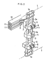
- Fig. 2 is an enlarged perspective view partially taken from the back of Fig. 1;
- Fig. 3 is an enlarged plan view of a heater part, partially illustrating it in a cutaway manner;
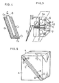
- Fig. 4 is a perspective view of a package containing a straw with 2 films; and
- Fig. 5 is a perspective view of a state in which said package is fitted up to a container.
- A paper container, so-called pack container as shown in Fig. 5, is used as a container for containing fruit juice or the like.
- While there are many cases where a straw is fitted to such a container A, when fruit juice or the like contained therein is on sale, said straw is packed with 2 strips of film for sanitary reasons as shown in Fig. 4. After gluing the packed straw to a side wall of the container A as shown in Fig. 5, the fruit juice or the like contained therein is placed on sale.
- For the purpose of such gluing, melt-welding and hot gluing technology by special bonding agent can be utilized. In performing this gluing work, an extremely efficient method lies in the process in which, when a package C is shown in Fig. 4 is conveyed so as to make an access to the container A which is forwarded through another course, such gluing work is arranged to be carried out.
- A pair of
long pins links endless chains - The holding device consists of two
holding pieces holding piece 3a is fixed to thepin 2a, anotherholding piece 3 is rotatably fitted up to thepin 2. A projectingpiece 3b is formed on theholding piece 3. When said projectingpiece 3b coincides with guide 4 provided within the chain (Fig. 1), theholding piece 3 swings in regard to theholding piece 3a, as if a mouth is opened, thereby making it easy to hold the package C therein and, on the contrary, when such coincidence does not occur, the above-mentioned twoholding pieces holding pieces groove 5, in which an expanded part C3 of the package C is preferably adapted to be grasped. - At the upper and lower sides of the above-mentioned
holding pieces pins heater bases heater bases heater 7 in a manner, that the partial part of theheater 7 extrudes from the outer side of theheater base 6. (Namely, the partial parts of theheaters heater base 6 in Fig. 3). - At the position corresponding to the
groove 5 notched between the above-mentionedholding pieces groove 8 is disposed between theheaters heater base 6, whereby the expanded part C3 of the package C, whose central part is put between theholding pieces groove 8. - The back of the
upper heater base 6 is equipped with pair of upper andlower contact segments 9, whose tips are respectively contacted with each of aconductor rails 11 andrail 10 provided withinchain 1. With such a composition the upper andlower heaters - With regard to other numerical symbols illustrated by the drawings, 12 is a long strip of article continuing the package C in a transversal direction of Fig. 4.
- 13 is a hold-down roller. 14 is a feed roller which performs an intermittent rotation in a counterclockwise direction of Fig. 1, when signal is given thereto, whereby the long strip of
article 12 can be fed out 1 pitch at a time (namely, the distance between a straw and a successive straw in the long strip of article 12). A plurality ofgrooves 14a are longitudinally (vertically) provided at regular intervals on the periphery of said feed roller 14. The expanded parts C3 of the long strip ofarticle 12 are one by one housed in each of saidgrooves 14a. - 15 is a cutting rotor which, located outside the feed roller 14, is provided near to the above-mentioned
chain 11. The periphery of thecutting rotor 15 is longitudinally (vertically) provided at regular intervals withnotched grooves 15a, of which front and rear peripheries are adapted to be acted on by a vacuum force. Thecutting rotor 15 and the feed roller 14 are synchronously rotated. - 16 is a cutter which rotates on its axis, while vertically revolving and plays the role of cutting the long strip of
article 12 held by vacuum on the periphery of thecutting rotor 15 into the packages C as shown in Fig. 4. The separated packages C, which are still held by vacuum on the periphery of thecutting rotor 15, are forwarded near to thechain 1 by the rotation thereof. - 17 is a conveyor for carrying the containers A which is installed in parallel to the
chain 1, travelling at the same speed as that ofchain 1. The containers A are carried by the conveyor in a manner than an upper corner's ridge part thereof, shown as in Fig. 5 is positioned right overhead. 18 is a guide which is provided outside theconveyor 17. - When each of the packages C, cut off from the long strip of
article 12 by the cutter 16 as shown in Fig. 4, which is still held by vacuum on the periphery of thecutting rotor 15, is forwarded near to thechain 1 by the rotation thereof, oneholding piece 3 composing the holding device fitted to thechain 1 travelling at the fixed speed straddles and the holding device makes an access to the periphery of cuttingrotor 15 similar to the condition of a mouth being opened. After that, as the projectingpart 3b of theholding piece 3 comes off the guide 4, the legs of the holding device close, thereby putting the package C held by vacuum on the periphery of thecutting rotor 15 between them. At that time, the expanded part C3 of the package C is grasped in thegroove 5 of the holding device and thegrooves down heater bases 6. - The package C put between the two pieces of the holding device is forwarded in an arrow direction as shown in Fig. 1 by the travelling of the chain and, subsequently, reaches a position to touch the side wall of the container A, which is carried by the
conveyor 17, so that said package C, still pressed against the side of theguide 18 by the holding device, is transferred together with the container A to the left direction on Fig. 1. - When the holding device is travelling along the side of the
rail 10, thecontact segments 9 are respectively by each of theconductor rails 11, thereby carrying electricity from outside to the up-and-downheaters rail 10, a contact bonding and melt-welding of the package to the side wall of the container are performed at the parts shown as D in Fig. 5 on both of the side edges C4 and C4 of said package C. - Thus, the package C is fitted up to the side wall of the container A in a diagonal direction.
- Since the
chain 1 and theconveyor 17 continue to be driven without cease, the projectingpiece 3b of oneholding piece 3 composing the holding device comes to coincide with the guide 4 in due course of time. At this moment theholding piece 3 straddles as if a mouth is opened. For this reason the package C is released from the holding device and the container A to which said package C has been fitted up moved directly to the left side of Fig. 1 by theconveyor 1. - Similarly to the above-mentioned case, the subsequent holding device conveys the following package, which is forwarded, while being still held by vacuum to the periphery of the
cutting rotor 15, to the welding process and said package C is melt-welded to the side wall of the container which is subsequently forwarded. - A repetition of this operation enables the conveyed packages as shown in Fig. 4 to be glued one by one to the side wall of the container A which is forwarded from a different course.
- According to the present invention, there is an effect of improving the working efficiency, because while an article to be glued, for example the package as shown in Fig. 4, and an article to which said package is glued are being transferred to each other, said package can be glued to the latter article.
- The above-mentioned embodiment illustrates the case where the article to be glued is the package containing a straw, whereas the article to which said package is glued is the paper container into which is poured the fruit juice or the like, but the present invention is not restricted to such a case. Needless to say, the embodiment illustrates the case where bonding is performed by melt-welding, but the present invention can be also brought into a practical work in which hot gluing is performed by using a special bonding agent.
Claims (2)
Applications Claiming Priority (2)
| Application Number | Priority Date | Filing Date | Title |
|---|---|---|---|
| JP21996/80 | 1980-02-22 | ||
| JP55021996A JPS5810294B2 (en) | 1980-02-22 | 1980-02-22 | Conveyance/adhesion equipment |
Publications (2)
| Publication Number | Publication Date |
|---|---|
| EP0035645A1 EP0035645A1 (en) | 1981-09-16 |
| EP0035645B1 true EP0035645B1 (en) | 1984-05-23 |
Family
ID=12070626
Family Applications (1)
| Application Number | Title | Priority Date | Filing Date |
|---|---|---|---|
| EP81100783A Expired EP0035645B1 (en) | 1980-02-22 | 1981-02-04 | Method of and apparatus for securing an article to a container |
Country Status (7)
| Country | Link |
|---|---|
| US (1) | US4384915A (en) |
| EP (1) | EP0035645B1 (en) |
| JP (1) | JPS5810294B2 (en) |
| AU (1) | AU543743B2 (en) |
| BR (1) | BR8101043A (en) |
| CA (1) | CA1163541A (en) |
| DE (1) | DE3163701D1 (en) |
Families Citing this family (37)
| Publication number | Priority date | Publication date | Assignee | Title |
|---|---|---|---|---|
| DE3204011A1 (en) * | 1982-02-05 | 1983-08-11 | Geyssel, Jürgen, 5000 Köln | DEVICE FOR ATTACHING OBJECTS TO PACKAGES, BOTTLES OR OTHER OBJECTS |
| JPS58216530A (en) * | 1982-05-27 | 1983-12-16 | 十條製紙株式会社 | Straw fixture |
| JPS58180103U (en) * | 1982-05-28 | 1983-12-01 | 大日本印刷株式会社 | Straw attachment device |
| MX157277A (en) * | 1982-12-24 | 1988-11-09 | Tetra Pak Int | IMPROVEMENTS IN MACHINE FOR THE PACKAGING OF GOODS AND METHOD OF PACKING |
| DE3311937A1 (en) * | 1983-03-31 | 1984-10-04 | Overbeck GmbH & Co, 2800 Bremen | DEVICE FOR ATTACHING DRINKING TUBES COVERED IN PROTECTIVE COVERINGS TO PRE-FABRICATED BEVERAGE PACKAGING CONTAINERS |
| SE454681B (en) * | 1983-06-23 | 1988-05-24 | Tetra Pak Ab | DEVICE FOR APPLICATION OF FORMAL ON PACKAGING CONTAINERS |
| DE3401214A1 (en) * | 1984-01-14 | 1985-07-25 | INDAG Gesellschaft für Industriebedarf mbH, 6900 Heidelberg | METHOD AND DEVICE FOR ATTACHING DRINKING STRAWS TO BEVERAGE CONTAINERS, ESPECIALLY TO BEVERAGE BAGS |
| US4605459A (en) * | 1984-02-03 | 1986-08-12 | New Jersey Machine Inc. | Literature applying machine and method |
| US4589947A (en) * | 1984-03-20 | 1986-05-20 | Kabushiki Kaisha Takara | Straw adhering apparatus for beverage vessels |
| JPS61101530U (en) * | 1984-12-11 | 1986-06-28 | ||
| JPH055131Y2 (en) * | 1985-04-23 | 1993-02-10 | ||
| DE3532839A1 (en) * | 1985-09-14 | 1987-03-26 | Overbeck Gmbh & Co | METHOD FOR ATTACHING DRINKING STRAWS TO PACKAGING CONTAINERS, AND APPARATUS FOR CARRYING OUT THE METHOD |
| US4718215A (en) * | 1985-11-27 | 1988-01-12 | Baxter Travenol Laboratories, Inc. | Apparatus and method for attaching fitments to flexible containers |
| SE463970B (en) * | 1987-03-24 | 1991-02-18 | Roby Teknik Ab | SUGROERSFOERPACKNING |
| SE463865B (en) * | 1987-09-04 | 1991-02-04 | Profor Ab | DEVICE AND WAY TO FIX AND FLEXIBLE SUGROS WITHIN THE SIDE OF A PACKAGING |
| DE3824013C2 (en) * | 1988-07-15 | 1997-02-13 | Profor Ab | Method of attaching a packed straw to a package and device for attaching the same |
| US5037366A (en) * | 1990-05-17 | 1991-08-06 | Gilliland Industrials Corporation | Device for attaching a straw to a carton container |
| DE4114191C1 (en) * | 1991-05-01 | 1992-04-23 | Ostma Maschinenbau Gmbh, 5352 Zuelpich, De | Application of long strip of material - involves conveyor belt and associated pressure and counter-pressure belts |
| SE509833C2 (en) | 1997-05-16 | 1999-03-15 | Tetra Laval Holdings & Finance | Device for application of straw |
| DE19745855C2 (en) * | 1997-10-16 | 2002-06-20 | Indag Gmbh | Drinking straw attachment device and method for attaching drinking straws to beverage film bags |
| NL1007683C2 (en) * | 1997-12-03 | 1999-06-07 | Antonius Adrianus Arnold Smits | Apparatus and method for applying objects to products. |
| US8353147B2 (en) * | 1998-07-17 | 2013-01-15 | Robert Beiser | Apparatus and method for manufacture of a top opening reclosable bag having a tape formed reclosable seal |
| US6726612B1 (en) * | 1998-07-17 | 2004-04-27 | Z-Patch, Inc. | Continuous supply of preformed reclosable fasteners |
| US6098369A (en) * | 1998-07-17 | 2000-08-08 | Bodolay; William A. | Apparatus for attaching a reclosable fastener to a flexible material |
| US20110235951A1 (en) * | 1998-07-17 | 2011-09-29 | Com-Pac International, Inc. | Reclosable bag with tear open feature |
| US6526725B1 (en) | 1999-06-23 | 2003-03-04 | Shrink Packaging Systems Corporation | Apparatus and method for attaching straws to containers |
| US6523328B1 (en) * | 1999-09-13 | 2003-02-25 | Gilbert L. De Cardenas | System and apparatus for an automated container filling production line |
| DE19952008A1 (en) * | 1999-10-28 | 2001-05-10 | Indag Gmbh | Device for attaching drinking straws |
| SE517051C2 (en) | 1999-12-10 | 2002-04-09 | Tetra Laval Holdings & Finance | Continuous device in a distribution equipment |
| ES2209799T3 (en) * | 2000-07-03 | 2004-07-01 | TETRA LAVAL HOLDINGS & FINANCE S.A. | PACKING MACHINE TO PRODUCE CONTINUOUSLY PACKS OBTAINED FROM A VERTIBLE FOOD PRODUCT AND WHICH IS PROVIDED WITH PROGRAMMABLE PHOTOELECTRIC CELLS. |
| RU2446082C1 (en) * | 2008-02-06 | 2012-03-27 | Тетра Лаваль Холдингз Энд Файнэнс С.А. | Device for application of straws on containers |
| WO2013109175A1 (en) * | 2012-01-20 | 2013-07-25 | Å&R Carton Lund Ab | Apparatus and method for placing a scoop in a container |
| EP3230170B1 (en) * | 2014-12-10 | 2019-06-12 | Tetra Laval Holdings & Finance SA | A method of operating an apparatus for applying drinking straws to packaging containers and an apparatus operated by the method |
| EP3233641B1 (en) * | 2014-12-15 | 2019-06-12 | Tetra Laval Holdings & Finance SA | A method of operating an apparatus for applying drinking straws to packaging containers and an apparatus operated by the method |
| DE102017109124A1 (en) * | 2017-04-27 | 2018-10-31 | Sig Technology Ag | Application device, application device and method for applying additional elements to packages |
| DE102017109118A1 (en) * | 2017-04-27 | 2018-10-31 | Sig Technology Ag | Application device and method for applying additional elements in an application orientation |
| CN112849586A (en) * | 2020-12-16 | 2021-05-28 | 宿州市同科机械有限公司 | Automatic pipe pasting machine |
Family Cites Families (6)
| Publication number | Priority date | Publication date | Assignee | Title |
|---|---|---|---|---|
| US2013475A (en) * | 1934-08-13 | 1935-09-03 | Tom Collins Corp | Package |
| US2435267A (en) * | 1946-05-15 | 1948-02-03 | Cons Lithographing Corp | Method of affixing labels, wraps, etc. |
| US3440116A (en) * | 1964-05-08 | 1969-04-22 | Smithkline Corp | Method and device for securing an article to a container |
| US3461647A (en) * | 1965-09-27 | 1969-08-19 | Paper & Corrugated Specialties | Heat sealing apparatus |
| SE424847B (en) * | 1978-01-30 | 1982-08-16 | Tetra Pak Int | MACHINE FOR APPLICATION OF SUGROR ON PACKAGING CONTAINER |
| US4233331A (en) * | 1978-07-31 | 1980-11-11 | American Can Company | Method of securing opener key to a container using oriented polypropylene film with solventless acrylic adhesive |
-
1980
- 1980-02-22 JP JP55021996A patent/JPS5810294B2/en not_active Expired
-
1981
- 1981-02-04 EP EP81100783A patent/EP0035645B1/en not_active Expired
- 1981-02-04 DE DE8181100783T patent/DE3163701D1/en not_active Expired
- 1981-02-16 CA CA000370934A patent/CA1163541A/en not_active Expired
- 1981-02-17 US US06/235,091 patent/US4384915A/en not_active Expired - Lifetime
- 1981-02-20 BR BR8101043A patent/BR8101043A/en not_active IP Right Cessation
- 1981-02-20 AU AU67513/81A patent/AU543743B2/en not_active Expired
Also Published As
| Publication number | Publication date |
|---|---|
| AU543743B2 (en) | 1985-05-02 |
| JPS56131139A (en) | 1981-10-14 |
| EP0035645A1 (en) | 1981-09-16 |
| AU6751381A (en) | 1981-08-27 |
| US4384915A (en) | 1983-05-24 |
| DE3163701D1 (en) | 1984-06-28 |
| CA1163541A (en) | 1984-03-13 |
| BR8101043A (en) | 1981-08-25 |
| JPS5810294B2 (en) | 1983-02-25 |
Similar Documents
| Publication | Publication Date | Title |
|---|---|---|
| EP0035645A1 (en) | Method of and apparatus for securing an article to a container | |
| US4041677A (en) | Packaging apparatus | |
| US4085560A (en) | Apparatus and method of forming covers for flexible commodity-containing packages | |
| JPS6013629A (en) | Device for pasting band-shaped body on vessel | |
| US4375146A (en) | Continuous rotary machine and method for forming, filling, and sealing package of laminated sheet material | |
| JPH04267716A (en) | Device and method for manufacturing packing carton | |
| FI853646A7 (en) | Apparatus and method for packaging a product in separate packages. | |
| US4819412A (en) | Process and apparatus for the manufacture of a package made of a thermoplastic synthetic sheet | |
| US4050216A (en) | Method of providing a package with a handle | |
| TR199801207A2 (en) | Packing unit for the continuous production of sealed packs. | |
| AU1997292A (en) | Method and apparatus for forming and hermetically sealing slices of food items | |
| US2626074A (en) | Supplying sheet material articles | |
| EP0034734B1 (en) | Method and apparatus for cutting and feeding packed articles from a continuous packaging strip | |
| US3998447A (en) | Method and apparatus for folding flaps of a sanitary pad | |
| US2969105A (en) | Apparatus for making pull-tab type closures and method | |
| US4722166A (en) | Packaging | |
| US4702060A (en) | Adjustable packaging device | |
| EP0887272A1 (en) | Reject device for a high-speed packaging machine | |
| GB2073130A (en) | Re-closeable Package | |
| JP2763995B2 (en) | Continuous supply method for individual packages | |
| ZA847506B (en) | Label wrapping machines | |
| KR100300269B1 (en) | Automatic Wrap Film Packing Machine | |
| US2201207A (en) | End label attachment | |
| EP0142904A2 (en) | A method and device for wrap packaging of articles | |
| KR850000236B1 (en) | Conveying and bonding apparatus |
Legal Events
| Date | Code | Title | Description |
|---|---|---|---|
| PUAI | Public reference made under article 153(3) epc to a published international application that has entered the european phase |
Free format text: ORIGINAL CODE: 0009012 |
|
| AK | Designated contracting states |
Designated state(s): CH DE FR GB IT NL SE |
|
| 17P | Request for examination filed |
Effective date: 19811030 |
|
| ITF | It: translation for a ep patent filed | ||
| GRAA | (expected) grant |
Free format text: ORIGINAL CODE: 0009210 |
|
| AK | Designated contracting states |
Designated state(s): CH DE FR GB IT LI NL SE |
|
| REF | Corresponds to: |
Ref document number: 3163701 Country of ref document: DE Date of ref document: 19840628 |
|
| ET | Fr: translation filed | ||
| PLBE | No opposition filed within time limit |
Free format text: ORIGINAL CODE: 0009261 |
|
| STAA | Information on the status of an ep patent application or granted ep patent |
Free format text: STATUS: NO OPPOSITION FILED WITHIN TIME LIMIT |
|
| 26N | No opposition filed | ||
| ITTA | It: last paid annual fee | ||
| EAL | Se: european patent in force in sweden |
Ref document number: 81100783.0 |
|
| PGFP | Annual fee paid to national office [announced via postgrant information from national office to epo] |
Ref country code: NL Payment date: 19980121 Year of fee payment: 18 |
|
| PGFP | Annual fee paid to national office [announced via postgrant information from national office to epo] |
Ref country code: CH Payment date: 19980126 Year of fee payment: 18 |
|
| PG25 | Lapsed in a contracting state [announced via postgrant information from national office to epo] |
Ref country code: LI Free format text: LAPSE BECAUSE OF NON-PAYMENT OF DUE FEES Effective date: 19990228 Ref country code: CH Free format text: LAPSE BECAUSE OF NON-PAYMENT OF DUE FEES Effective date: 19990228 |
|
| PG25 | Lapsed in a contracting state [announced via postgrant information from national office to epo] |
Ref country code: NL Free format text: LAPSE BECAUSE OF NON-PAYMENT OF DUE FEES Effective date: 19990901 |
|
| REG | Reference to a national code |
Ref country code: CH Ref legal event code: PL |
|
| PGFP | Annual fee paid to national office [announced via postgrant information from national office to epo] |
Ref country code: FR Payment date: 20000119 Year of fee payment: 20 |
|
| PGFP | Annual fee paid to national office [announced via postgrant information from national office to epo] |
Ref country code: SE Payment date: 20000120 Year of fee payment: 20 Ref country code: GB Payment date: 20000120 Year of fee payment: 20 Ref country code: DE Payment date: 20000120 Year of fee payment: 20 |
|
| PG25 | Lapsed in a contracting state [announced via postgrant information from national office to epo] |
Ref country code: GB Free format text: LAPSE BECAUSE OF EXPIRATION OF PROTECTION Effective date: 20010203 |
|
| PG25 | Lapsed in a contracting state [announced via postgrant information from national office to epo] |
Ref country code: SE Free format text: THE PATENT HAS BEEN ANNULLED BY A DECISION OF A NATIONAL AUTHORITY Effective date: 20010227 |
|
| REG | Reference to a national code |
Ref country code: GB Ref legal event code: PE20 Effective date: 20010203 |
|
| EUG | Se: european patent has lapsed |
Ref document number: 81100783.0 |