EP0035187B1 - Prolonged tack toners for the preparation of electric circuits - Google Patents
Prolonged tack toners for the preparation of electric circuits Download PDFInfo
- Publication number
- EP0035187B1 EP0035187B1 EP81101206A EP81101206A EP0035187B1 EP 0035187 B1 EP0035187 B1 EP 0035187B1 EP 81101206 A EP81101206 A EP 81101206A EP 81101206 A EP81101206 A EP 81101206A EP 0035187 B1 EP0035187 B1 EP 0035187B1
- Authority
- EP
- European Patent Office
- Prior art keywords
- prolonged tack
- weight
- toner
- metal particles
- image
- Prior art date
- Legal status (The legal status is an assumption and is not a legal conclusion. Google has not performed a legal analysis and makes no representation as to the accuracy of the status listed.)
- Expired
Links
- 230000002035 prolonged effect Effects 0.000 title claims description 47
- 238000002360 preparation method Methods 0.000 title description 5
- 239000011521 glass Substances 0.000 claims description 28
- 239000002923 metal particle Substances 0.000 claims description 19
- 239000004014 plasticizer Substances 0.000 claims description 15
- 239000002245 particle Substances 0.000 claims description 9
- 229920000642 polymer Polymers 0.000 claims description 9
- 239000000463 material Substances 0.000 claims description 7
- 229920000620 organic polymer Polymers 0.000 claims description 7
- CERQOIWHTDAKMF-UHFFFAOYSA-N Methacrylic acid Chemical compound CC(=C)C(O)=O CERQOIWHTDAKMF-UHFFFAOYSA-N 0.000 claims description 6
- 239000011236 particulate material Substances 0.000 claims description 6
- VVQNEPGJFQJSBK-UHFFFAOYSA-N Methyl methacrylate Chemical compound COC(=O)C(C)=C VVQNEPGJFQJSBK-UHFFFAOYSA-N 0.000 claims description 5
- XZZNDPSIHUTMOC-UHFFFAOYSA-N triphenyl phosphate Chemical compound C=1C=CC=CC=1OP(OC=1C=CC=CC=1)(=O)OC1=CC=CC=C1 XZZNDPSIHUTMOC-UHFFFAOYSA-N 0.000 claims description 5
- KDLHZDBZIXYQEI-UHFFFAOYSA-N Palladium Chemical compound [Pd] KDLHZDBZIXYQEI-UHFFFAOYSA-N 0.000 claims description 4
- BASFCYQUMIYNBI-UHFFFAOYSA-N platinum Chemical compound [Pt] BASFCYQUMIYNBI-UHFFFAOYSA-N 0.000 claims description 4
- 239000007787 solid Substances 0.000 claims description 4
- BQCADISMDOOEFD-UHFFFAOYSA-N Silver Chemical compound [Ag] BQCADISMDOOEFD-UHFFFAOYSA-N 0.000 claims description 3
- 229910052709 silver Inorganic materials 0.000 claims description 3
- 239000004332 silver Substances 0.000 claims description 3
- -1 toluenesulfonamide compound Chemical class 0.000 claims description 3
- RYGMFSIKBFXOCR-UHFFFAOYSA-N Copper Chemical compound [Cu] RYGMFSIKBFXOCR-UHFFFAOYSA-N 0.000 claims description 2
- 239000004793 Polystyrene Substances 0.000 claims description 2
- 229910052802 copper Inorganic materials 0.000 claims description 2
- 239000010949 copper Substances 0.000 claims description 2
- PCHJSUWPFVWCPO-UHFFFAOYSA-N gold Chemical compound [Au] PCHJSUWPFVWCPO-UHFFFAOYSA-N 0.000 claims description 2
- 229910052737 gold Inorganic materials 0.000 claims description 2
- 239000010931 gold Substances 0.000 claims description 2
- 229910052763 palladium Inorganic materials 0.000 claims description 2
- 229910052697 platinum Inorganic materials 0.000 claims description 2
- 229920002223 polystyrene Polymers 0.000 claims description 2
- 239000000758 substrate Substances 0.000 description 43
- 238000000034 method Methods 0.000 description 19
- 239000000203 mixture Substances 0.000 description 13
- 238000001816 cooling Methods 0.000 description 9
- 238000010438 heat treatment Methods 0.000 description 7
- 239000000725 suspension Substances 0.000 description 7
- 239000000155 melt Substances 0.000 description 6
- 229910052751 metal Inorganic materials 0.000 description 5
- 239000002184 metal Substances 0.000 description 5
- 238000002156 mixing Methods 0.000 description 5
- 239000005329 float glass Substances 0.000 description 4
- 239000000919 ceramic Substances 0.000 description 3
- 238000010304 firing Methods 0.000 description 3
- 238000005259 measurement Methods 0.000 description 3
- 230000005855 radiation Effects 0.000 description 3
- 238000005549 size reduction Methods 0.000 description 3
- CSCPPACGZOOCGX-UHFFFAOYSA-N Acetone Chemical compound CC(C)=O CSCPPACGZOOCGX-UHFFFAOYSA-N 0.000 description 2
- IJGRMHOSHXDMSA-UHFFFAOYSA-N Atomic nitrogen Chemical compound N#N IJGRMHOSHXDMSA-UHFFFAOYSA-N 0.000 description 2
- CURLTUGMZLYLDI-UHFFFAOYSA-N Carbon dioxide Chemical compound O=C=O CURLTUGMZLYLDI-UHFFFAOYSA-N 0.000 description 2
- XEEYBQQBJWHFJM-UHFFFAOYSA-N Iron Chemical compound [Fe] XEEYBQQBJWHFJM-UHFFFAOYSA-N 0.000 description 2
- 229910000831 Steel Inorganic materials 0.000 description 2
- 230000003213 activating effect Effects 0.000 description 2
- CXKCTMHTOKXKQT-UHFFFAOYSA-N cadmium oxide Inorganic materials [Cd]=O CXKCTMHTOKXKQT-UHFFFAOYSA-N 0.000 description 2
- 235000011089 carbon dioxide Nutrition 0.000 description 2
- 229910052573 porcelain Inorganic materials 0.000 description 2
- 239000002243 precursor Substances 0.000 description 2
- 239000011819 refractory material Substances 0.000 description 2
- 238000007650 screen-printing Methods 0.000 description 2
- 239000010959 steel Substances 0.000 description 2
- XLYOFNOQVPJJNP-UHFFFAOYSA-N water Substances O XLYOFNOQVPJJNP-UHFFFAOYSA-N 0.000 description 2
- AHSGHEXYEABOKT-UHFFFAOYSA-N 2-[2-(2-benzoyloxyethoxy)ethoxy]ethyl benzoate Chemical compound C=1C=CC=CC=1C(=O)OCCOCCOCCOC(=O)C1=CC=CC=C1 AHSGHEXYEABOKT-UHFFFAOYSA-N 0.000 description 1
- QPLDLSVMHZLSFG-UHFFFAOYSA-N Copper oxide Chemical compound [Cu]=O QPLDLSVMHZLSFG-UHFFFAOYSA-N 0.000 description 1
- 239000005751 Copper oxide Substances 0.000 description 1
- ATJFFYVFTNAWJD-UHFFFAOYSA-N Tin Chemical compound [Sn] ATJFFYVFTNAWJD-UHFFFAOYSA-N 0.000 description 1
- WGLPBDUCMAPZCE-UHFFFAOYSA-N Trioxochromium Chemical compound O=[Cr](=O)=O WGLPBDUCMAPZCE-UHFFFAOYSA-N 0.000 description 1
- BIBRSALWJZADJC-UHFFFAOYSA-N [O--].[O--].[O--].[Co++].[Zr+4] Chemical compound [O--].[O--].[O--].[Co++].[Zr+4] BIBRSALWJZADJC-UHFFFAOYSA-N 0.000 description 1
- 239000000654 additive Substances 0.000 description 1
- 230000000996 additive effect Effects 0.000 description 1
- PNEYBMLMFCGWSK-UHFFFAOYSA-N aluminium oxide Inorganic materials [O-2].[O-2].[O-2].[Al+3].[Al+3] PNEYBMLMFCGWSK-UHFFFAOYSA-N 0.000 description 1
- 239000011324 bead Substances 0.000 description 1
- CFEAAQFZALKQPA-UHFFFAOYSA-N cadmium(2+);oxygen(2-) Chemical compound [O-2].[Cd+2] CFEAAQFZALKQPA-UHFFFAOYSA-N 0.000 description 1
- 239000000969 carrier Substances 0.000 description 1
- 239000003795 chemical substances by application Substances 0.000 description 1
- 229910000423 chromium oxide Inorganic materials 0.000 description 1
- 229920001577 copolymer Polymers 0.000 description 1
- 229910000431 copper oxide Inorganic materials 0.000 description 1
- 230000003111 delayed effect Effects 0.000 description 1
- 230000001419 dependent effect Effects 0.000 description 1
- 238000000151 deposition Methods 0.000 description 1
- 238000007598 dipping method Methods 0.000 description 1
- 239000010408 film Substances 0.000 description 1
- 239000005357 flat glass Substances 0.000 description 1
- 238000007667 floating Methods 0.000 description 1
- 229910001938 gadolinium oxide Inorganic materials 0.000 description 1
- 229940075613 gadolinium oxide Drugs 0.000 description 1
- CMIHHWBVHJVIGI-UHFFFAOYSA-N gadolinium(iii) oxide Chemical compound [O-2].[O-2].[O-2].[Gd+3].[Gd+3] CMIHHWBVHJVIGI-UHFFFAOYSA-N 0.000 description 1
- 238000005816 glass manufacturing process Methods 0.000 description 1
- UQSXHKLRYXJYBZ-UHFFFAOYSA-N iron oxide Inorganic materials [Fe]=O UQSXHKLRYXJYBZ-UHFFFAOYSA-N 0.000 description 1
- 238000010030 laminating Methods 0.000 description 1
- 239000007788 liquid Substances 0.000 description 1
- 238000003801 milling Methods 0.000 description 1
- DKYVVNLWACXMDW-UHFFFAOYSA-N n-cyclohexyl-4-methylbenzenesulfonamide Chemical compound C1=CC(C)=CC=C1S(=O)(=O)NC1CCCCC1 DKYVVNLWACXMDW-UHFFFAOYSA-N 0.000 description 1
- 229910052757 nitrogen Inorganic materials 0.000 description 1
- TWNQGVIAIRXVLR-UHFFFAOYSA-N oxo(oxoalumanyloxy)alumane Chemical compound O=[Al]O[Al]=O TWNQGVIAIRXVLR-UHFFFAOYSA-N 0.000 description 1
- 238000010951 particle size reduction Methods 0.000 description 1
- 239000004033 plastic Substances 0.000 description 1
- 229920003023 plastic Polymers 0.000 description 1
- 229920000139 polyethylene terephthalate Polymers 0.000 description 1
- 239000005020 polyethylene terephthalate Substances 0.000 description 1
- 239000000843 powder Substances 0.000 description 1
- 238000007639 printing Methods 0.000 description 1
- 238000009877 rendering Methods 0.000 description 1
- 229920005989 resin Polymers 0.000 description 1
- 239000011347 resin Substances 0.000 description 1
- 238000000926 separation method Methods 0.000 description 1
- 239000002904 solvent Substances 0.000 description 1
- 238000003756 stirring Methods 0.000 description 1
- 229920005992 thermoplastic resin Polymers 0.000 description 1
Classifications
-
- G—PHYSICS
- G03—PHOTOGRAPHY; CINEMATOGRAPHY; ANALOGOUS TECHNIQUES USING WAVES OTHER THAN OPTICAL WAVES; ELECTROGRAPHY; HOLOGRAPHY
- G03G—ELECTROGRAPHY; ELECTROPHOTOGRAPHY; MAGNETOGRAPHY
- G03G9/00—Developers
- G03G9/08—Developers with toner particles
-
- G—PHYSICS
- G03—PHOTOGRAPHY; CINEMATOGRAPHY; ANALOGOUS TECHNIQUES USING WAVES OTHER THAN OPTICAL WAVES; ELECTROGRAPHY; HOLOGRAPHY
- G03F—PHOTOMECHANICAL PRODUCTION OF TEXTURED OR PATTERNED SURFACES, e.g. FOR PRINTING, FOR PROCESSING OF SEMICONDUCTOR DEVICES; MATERIALS THEREFOR; ORIGINALS THEREFOR; APPARATUS SPECIALLY ADAPTED THEREFOR
- G03F7/00—Photomechanical, e.g. photolithographic, production of textured or patterned surfaces, e.g. printing surfaces; Materials therefor, e.g. comprising photoresists; Apparatus specially adapted therefor
- G03F7/26—Processing photosensitive materials; Apparatus therefor
- G03F7/28—Processing photosensitive materials; Apparatus therefor for obtaining powder images
-
- G—PHYSICS
- G03—PHOTOGRAPHY; CINEMATOGRAPHY; ANALOGOUS TECHNIQUES USING WAVES OTHER THAN OPTICAL WAVES; ELECTROGRAPHY; HOLOGRAPHY
- G03G—ELECTROGRAPHY; ELECTROPHOTOGRAPHY; MAGNETOGRAPHY
- G03G9/00—Developers
- G03G9/08—Developers with toner particles
- G03G9/09—Colouring agents for toner particles
- G03G9/0926—Colouring agents for toner particles characterised by physical or chemical properties
-
- G—PHYSICS
- G03—PHOTOGRAPHY; CINEMATOGRAPHY; ANALOGOUS TECHNIQUES USING WAVES OTHER THAN OPTICAL WAVES; ELECTROGRAPHY; HOLOGRAPHY
- G03G—ELECTROGRAPHY; ELECTROPHOTOGRAPHY; MAGNETOGRAPHY
- G03G9/00—Developers
- G03G9/08—Developers with toner particles
- G03G9/097—Plasticisers; Charge controlling agents
- G03G9/09708—Inorganic compounds
-
- G—PHYSICS
- G03—PHOTOGRAPHY; CINEMATOGRAPHY; ANALOGOUS TECHNIQUES USING WAVES OTHER THAN OPTICAL WAVES; ELECTROGRAPHY; HOLOGRAPHY
- G03G—ELECTROGRAPHY; ELECTROPHOTOGRAPHY; MAGNETOGRAPHY
- G03G9/00—Developers
- G03G9/08—Developers with toner particles
- G03G9/097—Plasticisers; Charge controlling agents
- G03G9/09733—Organic compounds
-
- G—PHYSICS
- G03—PHOTOGRAPHY; CINEMATOGRAPHY; ANALOGOUS TECHNIQUES USING WAVES OTHER THAN OPTICAL WAVES; ELECTROGRAPHY; HOLOGRAPHY
- G03G—ELECTROGRAPHY; ELECTROPHOTOGRAPHY; MAGNETOGRAPHY
- G03G9/00—Developers
- G03G9/08—Developers with toner particles
- G03G9/097—Plasticisers; Charge controlling agents
- G03G9/09733—Organic compounds
- G03G9/09775—Organic compounds containing atoms other than carbon, hydrogen or oxygen
-
- H—ELECTRICITY
- H05—ELECTRIC TECHNIQUES NOT OTHERWISE PROVIDED FOR
- H05K—PRINTED CIRCUITS; CASINGS OR CONSTRUCTIONAL DETAILS OF ELECTRIC APPARATUS; MANUFACTURE OF ASSEMBLAGES OF ELECTRICAL COMPONENTS
- H05K3/00—Apparatus or processes for manufacturing printed circuits
- H05K3/10—Apparatus or processes for manufacturing printed circuits in which conductive material is applied to the insulating support in such a manner as to form the desired conductive pattern
- H05K3/102—Apparatus or processes for manufacturing printed circuits in which conductive material is applied to the insulating support in such a manner as to form the desired conductive pattern by bonding of conductive powder, i.e. metallic powder
-
- H—ELECTRICITY
- H05—ELECTRIC TECHNIQUES NOT OTHERWISE PROVIDED FOR
- H05K—PRINTED CIRCUITS; CASINGS OR CONSTRUCTIONAL DETAILS OF ELECTRIC APPARATUS; MANUFACTURE OF ASSEMBLAGES OF ELECTRICAL COMPONENTS
- H05K1/00—Printed circuits
- H05K1/02—Details
- H05K1/03—Use of materials for the substrate
- H05K1/0306—Inorganic insulating substrates, e.g. ceramic, glass
-
- H—ELECTRICITY
- H05—ELECTRIC TECHNIQUES NOT OTHERWISE PROVIDED FOR
- H05K—PRINTED CIRCUITS; CASINGS OR CONSTRUCTIONAL DETAILS OF ELECTRIC APPARATUS; MANUFACTURE OF ASSEMBLAGES OF ELECTRICAL COMPONENTS
- H05K2203/00—Indexing scheme relating to apparatus or processes for manufacturing printed circuits covered by H05K3/00
- H05K2203/05—Patterning and lithography; Masks; Details of resist
- H05K2203/0502—Patterning and lithography
- H05K2203/0525—Patterning by phototackifying or by photopatterning adhesive
-
- H—ELECTRICITY
- H05—ELECTRIC TECHNIQUES NOT OTHERWISE PROVIDED FOR
- H05K—PRINTED CIRCUITS; CASINGS OR CONSTRUCTIONAL DETAILS OF ELECTRIC APPARATUS; MANUFACTURE OF ASSEMBLAGES OF ELECTRICAL COMPONENTS
- H05K2203/00—Indexing scheme relating to apparatus or processes for manufacturing printed circuits covered by H05K3/00
- H05K2203/11—Treatments characterised by their effect, e.g. heating, cooling, roughening
- H05K2203/1131—Sintering, i.e. fusing of metal particles to achieve or improve electrical conductivity
-
- H—ELECTRICITY
- H05—ELECTRIC TECHNIQUES NOT OTHERWISE PROVIDED FOR
- H05K—PRINTED CIRCUITS; CASINGS OR CONSTRUCTIONAL DETAILS OF ELECTRIC APPARATUS; MANUFACTURE OF ASSEMBLAGES OF ELECTRICAL COMPONENTS
- H05K3/00—Apparatus or processes for manufacturing printed circuits
- H05K3/38—Improvement of the adhesion between the insulating substrate and the metal
Definitions
- This invention relates to prolonged tack toners. More particularly the invention relates to prolonged tack toners containing conductive metal particles and glass frit.
- compositions comprising carriers or vehicles, conductive metal particles and glass frit are known.
- the carrier or vehicle can be polymerizable or nonpolymerizable to actinic radiation.
- these compositions are placed on the inert substrate by printing techniques such as screen printing. After firing the image on the inert substrate a useful electrically conductive circuit is obtained. Screen printing has limited resolution capabilities.
- a prolonged tack toner consisting of an organic polymer, a solid plasticizer for the polymer, electrically conductive metal particles, glass frit, and optionally finely divided inorganic particulate nonglass forming materials, the plasticizer being present in an amount greater than its compatibility level in the polymer.
- Prolonged tack toners means toners that are nontacky at normal room temperatures but upon heating to an elevated temperature become and remain tacky for a period of time even though the temperature of the toner returns or is returned to a temperature below the temperature at which the toner becomes tacky, including room temperature. Such toners are sometimes referred to as delayed tack toners.
- the prolonged tack toners of this invention consist essentially of (1) an organic polymer such as a thermoplastic resin, (2) a plasticizer or heat activatable tackifying agent solid at room temperature present in an amount greater than its compatibility level in the polymer, (3) electrically conductive metal particles, (4) glass frit, and, optionally, (5) finely divided inorganic particulate nonglass forming materials which are refractory.
- organic polymer (1) and plasticizer (2) examples include: polystyrene and N-cyclohexyl-p-toluenesulfonamide, poly(methylmethacrylate(90)/methacrylic acid(10)) and triphenyl phosphate, styrene/maleic anhydride copolymer and triethylene glycol dibenzoate, etc.
- poly(methylmethacrylate/methacrylic acid) and triphenyl phosphate plasticizer the latter component is present in an amount greater than 48% by weight based on the weight of polymer and plasticizer.
- the electrically conductive metal particles (3) are taken from the group consisting of silver, gold, platinum, copper, palladium and combinations thereof.
- the particle size range is 0.3 to 10 jlm (majority 1 to 5 pm) with the particles being spherical, random or flake in shape.
- the metal particles are present in an amount of about 86 to 98% by weight based on the weight of metal particles (3), glass frit (4) and any inorganic particulate material (5) present.
- the glass frit has a softening point range of 325-600°C.
- Preferred glass frits include the lead boro-silicate-type glasses; an especially preferred composition is (mol%): PbO (53.1), B 2 0 3 (2.9), Si0 2 (29.0), Ti0 2 (3.0), Zr0 2 (3.0), ZnO (2.0), Ma 2 0 (3.0), and CdO (4.0).
- the glasses can be prepared by conventional glass-making techniques, by mixing the desired components (or precursors thereof, e.g., H 3 B0 3 for B 2 0 3 ) in the desired proportions and heating the mixture to form a melt. Heating is conducted to a peak temperature and for a time such that the melt becomes entirely liquid, yet gaseous evolution has caused.
- the peak temperature is in the range of 1100-1500°C, usually 1200-1400 0 C.
- the melt is then fritted by cooling the melt, e.g., by pouring onto a cold belt or into cold running water. Particle size reductions can be accomplished by milling.
- the glass frit is present in an amount of 1.3 to 10.3% by weight based on the weight of metal particles (3), glass frit (4) and any inorganic particulate material (5) present.
- Finely divided inorganic particulate nonglass forming materials which are refractory can optionally be present in the prolonged tack toner.
- Useful materials include: aluminum oxide, copper oxide, cadmium oxide, gadolinium oxide, zirconium oxide cobalt/iron/chromium oxide, etc.
- the oxides or their oxide precursors have a particle size range of 0.5 to 44.0 micrometers, with at least 80% by weight of the particles in the 0.1 to 5.0 micrometer range.
- the inorganic particulate refractory material can be present in amounts up to 45.0% by weight based on the weight of the glass frit (4) and the inorganic particulate refractory material (5) preferably about 25.0% by weight.
- the prolonged tack toners of this invention can be made by physical mixing, melt suspension technique and other methods known to those skilled in the art.
- a toner-receptive image is generated thereon.
- Float glass is plate glass made by floating the glass while cooling on a bed of molten tin to provide a smooth surface adequate for the preparation of metallic conductive circuits.
- the toner-receptive image may be formed on the inert substrate directly, e.g., by applying a tacky material onto the inert substrate in an imagewise manner or by applying a layer of tacky photosensitive composition to the inert substrate and imagewise exposing the layer whereby only the unexposed areas remain tacky and toner-receptive.
- the toner-receptive image may also be formed on the inert substrate by laminating as described in U.S. Patent 4,174,216 a negative peel apart photosensitive element to the substrate, imagewise exposing the photosensitive element, stripping the cover sheet and toning the toner-receptive tacky areas.
- a latent toner receptive image can be formed on a master substrate, e.g., polymeric film, plastic, metal or sheet such as paper, whereon it adheres, and, after applying prolonged tack toner, which is then activated, the toned image can be transferred to an inert substrate.
- a master substrate e.g., polymeric film, plastic, metal or sheet such as paper
- the toned image can be transferred to an inert substrate.
- "Latent toner receptive image on the substrate master” means any image capable of being developed through the application of toner particles, including, but not limited to, electrostatic images, electromagnetic images, or images comprising tacky areas and nontacky background areas.
- the tacky images can be formed directly, e.g., by exposure to actinic radiation, or by treatment with solutions, heat, or other means.
- the tacky images are formed in photosensitive layers which may be comprised of positive- working or negative-working compositions.
- a prolonged tack toner is applied to produce a nontacky toned image.
- this toner contains organic polymer and plasticizer solid at room temperature without the metal particles and glass frit.
- the toned image is heated to a temperature sufficient to activate the toner by rendering the toner tacky.
- the master substrate with its toned tacky image is then brought into intimate contact with an inert substrate, and while the toner is still activated, the master substrate and inert substrate are separated. A portion of the activated prolonged tack toner transfers imagewise from the master substrate to the inert substrate.
- the temperature of the tackified toned master substrate is reduced (or permitted to be reduced) below the activating temperature of the prolonged tack toner wherein the toner remains tacky and prolonged tack toner is again applied over the remaining prolonged tack toner on the master substrate and the steps of heating the toner, contacting the toner with the new inert substrate and separating the surfaces are repeated.
- Each repetition of the process requires a new inert substrate. It is also possible to build up the toned image on an inert substrate by repeating the process as described above.
- a process for image development of a latent image on a master substrate and transferring the toned image to another substrate is described in EP-A-81 101 205.3.
- the toned image areas are activated by heating, and the temperature is reduced below the activating temperature, wherein the activated prolonged tack toner remains tacky.
- a prolonged tack toner comprising organic polymer, plasticizer, conductive metal particles and glass frit, as described above, is then applied to the tackified toned image. Additional amounts of the particulate metal containing toner can be applied to the image as described. It has been found desirable to apply as a final toner, a prolonged tack toner containing greater amounts of metal particles.
- the organic polymer and plasticizer components of the prolonged tack toner are burned off by increasing the temperature of the inert substrate and toned image. Subsequently, the inert substrate and toned image are fired to a temperature sufficient to fuse the glass frit and sinter the metal particles.
- the burning and firing temperatures used are dependent on the materials present in the toned image. A temperature range found useful for burning is 320 to 450°C. A firing temperature range is 540 to 950°C.
- the inert substrates described above are not affected by the elevated temperatures or the manner in which the image is generated thereon. The process for preparation of an electrically conductive image on an inert substrate is described in EP-A-81 101 207.9.
- the prolonged tack toners are useful for the preparation of electrically conductive images or circuits on inert substrates, e.g., AC plasma display electrodes for computer video display output.
- the prolonged tack toners are prepared by physical mixing.
- the prolonged tack toners are prepared by a melt suspension process as follows: triphenyl phosphate is melted in a beaker and the poly(methylmethacrylate/methacrylic acid) is added with mixing until it dissolves. Metal powder and glass frit are stirred into the mixture to prepare a uniform suspension. The suspension is cooled by immersing in dry ice including pouring some dry ice over the suspension. After cooling, the hardened suspension is chipped out of the beaker and is ground to a particle size of 50 to 250 pm using a standard size reduction machine such as an Osterizer@.
- size reduction is accomplished by actuating the machine for short periods of time, e.g., 3 to 5 seconds and not more than 10 seconds. Following size reduction, the particles are wet ball milled for about 45 minutes in the presence of water using a vertical ball mill comprising a metal beaker, Dragonite@ glass beads and a stirring rod turning at about 200 rpm. The particles at this point are in the range of 5 to 10 j l m average size.
- the milled toner is filtered and dried, preferably in a low humidity environment. Prior to use the toner is ground to break up any agglomerates present.
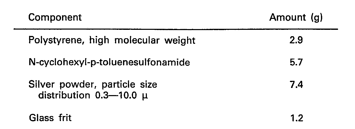
- a prolonged tack toner is prepared by mixing in a suitable mixer the following components in the amounts indicated:
- a tacky solution of the following composition is prepared:
- lines are painted on a clean, dry glass substrate at room temperature.
- the solvent is allowed to evaporate leaving a tacky clear image.
- the tacky image is toned with the above-described prolonged tack toner.
- the toned image is heated above the temperature sufficient to melt the prolonged tack toner, the temperature is permitted to return to room temperature, and the toned image is retoned with the same toner.
- the retoned image is burned at about 425°C for about one hour and then fired at a temperature of about 615°C for about one hour.
- the resistivity measurements on the electrically conductive lines are measured as 0.0025 ohm/square.
- Example 2 The procedure of Example 1 is repeated except that the prolonged tack toner is of the following composition:
- the resistivity measurements on the electrically conductive lines are measured as 0.0025 ohm/square.
- Example 3 prolonged tack toner is applied to a 0.0004 inch (0.01 mm) thick photohardenable layer supported by a polyethylene terephthalate support coated with a resin sublayer.
- the photohardenable layer is of the following composition:
- the exposed surface of the photohardened layer is toned by hand with a pad using a prolonged tack toner containing triphenyl phosphate 14.0 g and poly(methylmethacrylate (90)/methacrylic acid (10)) 6.0 g.
- the toned layer is heated to about 60°C, the temperature is reduced to below 60°C with the toner remaining tacky, and additional identical prolonged tack toner is applied.
- the retoned image is heated to 60°C to tackify the toner.
- a float glass substrate preheated to 75 to 85°C is brought into contact with the tacky image and upon separation the tacky toned image transfers to the glass substrate.
- the transferred image is toned eight times with the prolonged tack toner described in the Table by heating, cooling and toning.
- the toned image is heated to 320°C, held for one hour, is heated to 450°C, held for one hour and is then fired at 615°C for one hour. After cooling slowly the resistivity measurements on the electrically conductive lines are measured as 0.034 ohm/square.
- Example 4 a prolonged tack toner of the following composition is coated on an imaged photohardenable element as described in Example 3.
- the eight-times toned element is then heated, fired and cooled following the procedure described in Example 3.
- the measured resistivity is 0.112 to 0.130 ohm/square.
- Example 5 a prolonged tack toner described in the Table above is applied to the surface of an imaged photohardenable element as described in Example 3.
- the toned image is heated to 60°C for thirty seconds to melt the toner which is then transferred to a glass substrate preheated to 85°C by the procedure described in Example 3.
- the transferred image is retoned twice with the toner described in the above Table using the procedure described in Example 3.
- the toned surface is then retoned once using the following nonprolonged tack toner.
- the toned image is heated in an oven at about 320°C for one half hour and is heated at 420°C for another half hour.
- the toned image is then fired in an oven at about 615°C to fuse the glass frit and sinter the silver powder, followed by cooling.
- the electrically conductive image formed has a resistivity of 0.14 ohm/square.
- Example 6 a prolonged tack toner described in the Table above is applied twice to the surface of an imaged photohardenable element as described in Example 3. Following toning the image is transferred to the clean surface of a substrate of porcelain on steel backing which is preheated under infrared radiation to about 88°C. The transferred image is toned three times by the procedure described in Example 3 again using the prolonged tack toner described in the Table above. A final nonprolonged tack toner of the following composition is applied:
- Example 3 Using the procedure of Example 3, the cycle is repeated three more times to provide a total of twelve layers.
- the toned element is heated and fired as described in Example 3. After cooling, the resistivity is measured as 0.001 to 0.002 ohm/square.
- Example 7 a flat ceramic substrate comprising porous alumina is cleaned and prepared by dipping in a 1% solution of poly(methylmethacylate (90)/methacrylic acid (10)) in acetone. An image is formed on the surface of a photohardenable element as described in Example 3, the image being toned twice with the following toner:
- Example 6 Using the procedure described in Example 6, the image is transferred to the ceramic substrate and is toned once more with the above toner. The toned, transferred image is then toned as described in Example 6 three times with prolonged tack toner (a) of the above Table followed by one application of prolonged tack toner (b) of the above Table for a total of four separate cycles, i.e., the total toned layers is fifteen.
- the toned element is fired for one hour in a nitrogen belt type furnace set to reach a peak temperature of 900°C. After cooling, the resistivity is measured as 0.004 to 0.008 ohm/square.
Landscapes
- Physics & Mathematics (AREA)
- General Physics & Mathematics (AREA)
- Engineering & Computer Science (AREA)
- Chemical & Material Sciences (AREA)
- Inorganic Chemistry (AREA)
- Manufacturing & Machinery (AREA)
- Microelectronics & Electronic Packaging (AREA)
- Developing Agents For Electrophotography (AREA)
- Conductive Materials (AREA)
- Manufacturing Of Printed Wiring (AREA)
Description
- This invention relates to prolonged tack toners. More particularly the invention relates to prolonged tack toners containing conductive metal particles and glass frit.
- The preparation of electrically conductive images or circuits on inert substrates using compositions comprising carriers or vehicles, conductive metal particles and glass frit is known. The carrier or vehicle can be polymerizable or nonpolymerizable to actinic radiation. Generally these compositions are placed on the inert substrate by printing techniques such as screen printing. After firing the image on the inert substrate a useful electrically conductive circuit is obtained. Screen printing has limited resolution capabilities.
- It is desirable to prepare electrically conductive circuits on inert substrates by an additive method wherein a high resolution image of the circuit can be formed directly without need for developing the image. To form such a circuit a need existed for a new type of toner which is capable of depositing on a substrate sufficient glass and conductive metal to provide a high quality fused conductive circuit.
- In accordance with this invention there is provided a prolonged tack toner consisting of an organic polymer, a solid plasticizer for the polymer, electrically conductive metal particles, glass frit, and optionally finely divided inorganic particulate nonglass forming materials, the plasticizer being present in an amount greater than its compatibility level in the polymer.
- The term "prolonged tack toners" means toners that are nontacky at normal room temperatures but upon heating to an elevated temperature become and remain tacky for a period of time even though the temperature of the toner returns or is returned to a temperature below the temperature at which the toner becomes tacky, including room temperature. Such toners are sometimes referred to as delayed tack toners. The prolonged tack toners of this invention consist essentially of (1) an organic polymer such as a thermoplastic resin, (2) a plasticizer or heat activatable tackifying agent solid at room temperature present in an amount greater than its compatibility level in the polymer, (3) electrically conductive metal particles, (4) glass frit, and, optionally, (5) finely divided inorganic particulate nonglass forming materials which are refractory.
- Examples of combination of organic polymer (1) and plasticizer (2) include: polystyrene and N-cyclohexyl-p-toluenesulfonamide, poly(methylmethacrylate(90)/methacrylic acid(10)) and triphenyl phosphate, styrene/maleic anhydride copolymer and triethylene glycol dibenzoate, etc. In the combination of poly(methylmethacrylate/methacrylic acid) and triphenyl phosphate plasticizer the latter component is present in an amount greater than 48% by weight based on the weight of polymer and plasticizer.
- The electrically conductive metal particles (3) are taken from the group consisting of silver, gold, platinum, copper, palladium and combinations thereof. The particle size range is 0.3 to 10 jlm (majority 1 to 5 pm) with the particles being spherical, random or flake in shape. The metal particles are present in an amount of about 86 to 98% by weight based on the weight of metal particles (3), glass frit (4) and any inorganic particulate material (5) present.
- The glass frit has a softening point range of 325-600°C. Preferred glass frits include the lead boro-silicate-type glasses; an especially preferred composition is (mol%): PbO (53.1), B203 (2.9), Si02 (29.0), Ti02 (3.0), Zr02 (3.0), ZnO (2.0), Ma20 (3.0), and CdO (4.0). The glasses can be prepared by conventional glass-making techniques, by mixing the desired components (or precursors thereof, e.g., H3B03 for B203) in the desired proportions and heating the mixture to form a melt. Heating is conducted to a peak temperature and for a time such that the melt becomes entirely liquid, yet gaseous evolution has caused. The peak temperature is in the range of 1100-1500°C, usually 1200-14000C. The melt is then fritted by cooling the melt, e.g., by pouring onto a cold belt or into cold running water. Particle size reductions can be accomplished by milling. The glass frit is present in an amount of 1.3 to 10.3% by weight based on the weight of metal particles (3), glass frit (4) and any inorganic particulate material (5) present.
- Finely divided inorganic particulate nonglass forming materials which are refractory can optionally be present in the prolonged tack toner. Useful materials include: aluminum oxide, copper oxide, cadmium oxide, gadolinium oxide, zirconium oxide cobalt/iron/chromium oxide, etc. The oxides or their oxide precursors have a particle size range of 0.5 to 44.0 micrometers, with at least 80% by weight of the particles in the 0.1 to 5.0 micrometer range. The inorganic particulate refractory material can be present in amounts up to 45.0% by weight based on the weight of the glass frit (4) and the inorganic particulate refractory material (5) preferably about 25.0% by weight.
- The prolonged tack toners of this invention can be made by physical mixing, melt suspension technique and other methods known to those skilled in the art.
- In preparing an electrically conductive image or circuit on an inert substrate, e.g., glass plate or sheet, e.g., float glass; ceramic, porcelain on steel, a toner-receptive image is generated thereon. Float glass is plate glass made by floating the glass while cooling on a bed of molten tin to provide a smooth surface adequate for the preparation of metallic conductive circuits. The toner-receptive image may be formed on the inert substrate directly, e.g., by applying a tacky material onto the inert substrate in an imagewise manner or by applying a layer of tacky photosensitive composition to the inert substrate and imagewise exposing the layer whereby only the unexposed areas remain tacky and toner-receptive. The toner-receptive image may also be formed on the inert substrate by laminating as described in U.S. Patent 4,174,216 a negative peel apart photosensitive element to the substrate, imagewise exposing the photosensitive element, stripping the cover sheet and toning the toner-receptive tacky areas.
- Alternatively, a latent toner receptive image can be formed on a master substrate, e.g., polymeric film, plastic, metal or sheet such as paper, whereon it adheres, and, after applying prolonged tack toner, which is then activated, the toned image can be transferred to an inert substrate. "Latent toner receptive image on the substrate master", as used in this specification, means any image capable of being developed through the application of toner particles, including, but not limited to, electrostatic images, electromagnetic images, or images comprising tacky areas and nontacky background areas. The tacky images can be formed directly, e.g., by exposure to actinic radiation, or by treatment with solutions, heat, or other means. Preferably the tacky images are formed in photosensitive layers which may be comprised of positive- working or negative-working compositions.
- After the latent toner receptive image is formed on the master substrate a prolonged tack toner is applied to produce a nontacky toned image. Generally, this toner contains organic polymer and plasticizer solid at room temperature without the metal particles and glass frit. The toned image is heated to a temperature sufficient to activate the toner by rendering the toner tacky. The master substrate with its toned tacky image is then brought into intimate contact with an inert substrate, and while the toner is still activated, the master substrate and inert substrate are separated. A portion of the activated prolonged tack toner transfers imagewise from the master substrate to the inert substrate.
- In order to form a duplicate image on another inert substrate, the temperature of the tackified toned master substrate is reduced (or permitted to be reduced) below the activating temperature of the prolonged tack toner wherein the toner remains tacky and prolonged tack toner is again applied over the remaining prolonged tack toner on the master substrate and the steps of heating the toner, contacting the toner with the new inert substrate and separating the surfaces are repeated. Each repetition of the process requires a new inert substrate. It is also possible to build up the toned image on an inert substrate by repeating the process as described above. A process for image development of a latent image on a master substrate and transferring the toned image to another substrate is described in EP-A-81 101 205.3.
- After the prolonged tack toner image is obtained on the inert substrate, the toned image areas are activated by heating, and the temperature is reduced below the activating temperature, wherein the activated prolonged tack toner remains tacky. A prolonged tack toner comprising organic polymer, plasticizer, conductive metal particles and glass frit, as described above, is then applied to the tackified toned image. Additional amounts of the particulate metal containing toner can be applied to the image as described. It has been found desirable to apply as a final toner, a prolonged tack toner containing greater amounts of metal particles.
- The organic polymer and plasticizer components of the prolonged tack toner are burned off by increasing the temperature of the inert substrate and toned image. Subsequently, the inert substrate and toned image are fired to a temperature sufficient to fuse the glass frit and sinter the metal particles. The burning and firing temperatures used are dependent on the materials present in the toned image. A temperature range found useful for burning is 320 to 450°C. A firing temperature range is 540 to 950°C. The inert substrates described above are not affected by the elevated temperatures or the manner in which the image is generated thereon. The process for preparation of an electrically conductive image on an inert substrate is described in EP-A-81 101 207.9.
- The best mode is illustrated in Example 5.
- The prolonged tack toners are useful for the preparation of electrically conductive images or circuits on inert substrates, e.g., AC plasma display electrodes for computer video display output.
- The following examples illustrate the invention wherein the parts and percentages are by weight. In examples 1 and 2, the prolonged tack toners are prepared by physical mixing. In Examples 3 to 7, the prolonged tack toners are prepared by a melt suspension process as follows: triphenyl phosphate is melted in a beaker and the poly(methylmethacrylate/methacrylic acid) is added with mixing until it dissolves. Metal powder and glass frit are stirred into the mixture to prepare a uniform suspension. The suspension is cooled by immersing in dry ice including pouring some dry ice over the suspension. After cooling, the hardened suspension is chipped out of the beaker and is ground to a particle size of 50 to 250 pm using a standard size reduction machine such as an Osterizer@. Care is taken at this stage not to generate heat sufficient to melt the toner. In practice, size reduction is accomplished by actuating the machine for short periods of time, e.g., 3 to 5 seconds and not more than 10 seconds. Following size reduction, the particles are wet ball milled for about 45 minutes in the presence of water using a vertical ball mill comprising a metal beaker, Dragonite@ glass beads and a stirring rod turning at about 200 rpm. The particles at this point are in the range of 5 to 10 jlm average size. The milled toner is filtered and dried, preferably in a low humidity environment. Prior to use the toner is ground to break up any agglomerates present.
- A prolonged tack toner is prepared by mixing in a suitable mixer the following components in the amounts indicated:
- A tacky solution of the following composition is prepared:

- Using the tacky solution, lines are painted on a clean, dry glass substrate at room temperature. The solvent is allowed to evaporate leaving a tacky clear image. The tacky image is toned with the above-described prolonged tack toner. The toned image is heated above the temperature sufficient to melt the prolonged tack toner, the temperature is permitted to return to room temperature, and the toned image is retoned with the same toner. The retoned image is burned at about 425°C for about one hour and then fired at a temperature of about 615°C for about one hour. The resistivity measurements on the electrically conductive lines are measured as 0.0025 ohm/square.
- The procedure of Example 1 is repeated except that the prolonged tack toner is of the following composition:

- The resistivity measurements on the electrically conductive lines are measured as 0.0025 ohm/square.
- The following prolonged tack toners having the composition set forth in the Table are prepared by the melt suspension procedure described above.

- The Example 3 prolonged tack toner is applied to a 0.0004 inch (0.01 mm) thick photohardenable layer supported by a polyethylene terephthalate support coated with a resin sublayer. The photohardenable layer is of the following composition:

- After imagewise exposure for 40 seconds in a vacuum frame to a 2 KW standup Adalux® light source equipped with a "photopolymer bulb", the exposed surface of the photohardened layer is toned by hand with a pad using a prolonged tack toner containing triphenyl phosphate 14.0 g and poly(methylmethacrylate (90)/methacrylic acid (10)) 6.0 g. The toned layer is heated to about 60°C, the temperature is reduced to below 60°C with the toner remaining tacky, and additional identical prolonged tack toner is applied. The retoned image is heated to 60°C to tackify the toner. A float glass substrate preheated to 75 to 85°C is brought into contact with the tacky image and upon separation the tacky toned image transfers to the glass substrate. The transferred image is toned eight times with the prolonged tack toner described in the Table by heating, cooling and toning. The toned image is heated to 320°C, held for one hour, is heated to 450°C, held for one hour and is then fired at 615°C for one hour. After cooling slowly the resistivity measurements on the electrically conductive lines are measured as 0.034 ohm/square.
- In Example 4 a prolonged tack toner of the following composition is coated on an imaged photohardenable element as described in Example 3.

- The toned image is transferred to a float glass substrate at 75 to 85°C using pressure rolls. The transferred image is toned six times with the toner described in the above Table, followed by two times with the toner set forth below that does not exhibit prolonged tack properties using the same process of toning, heating to activate, cooling and retoning as described in Example 3.

- The eight-times toned element is then heated, fired and cooled following the procedure described in Example 3. The measured resistivity is 0.112 to 0.130 ohm/square.
- In Example 5, a prolonged tack toner described in the Table above is applied to the surface of an imaged photohardenable element as described in Example 3. The toned image is heated to 60°C for thirty seconds to melt the toner which is then transferred to a glass substrate preheated to 85°C by the procedure described in Example 3. The transferred image is retoned twice with the toner described in the above Table using the procedure described in Example 3. The toned surface is then retoned once using the following nonprolonged tack toner.

- The toned image is heated in an oven at about 320°C for one half hour and is heated at 420°C for another half hour. The toned image is then fired in an oven at about 615°C to fuse the glass frit and sinter the silver powder, followed by cooling. The electrically conductive image formed has a resistivity of 0.14 ohm/square.
- In Example 6, a prolonged tack toner described in the Table above is applied twice to the surface of an imaged photohardenable element as described in Example 3. Following toning the image is transferred to the clean surface of a substrate of porcelain on steel backing which is preheated under infrared radiation to about 88°C. The transferred image is toned three times by the procedure described in Example 3 again using the prolonged tack toner described in the Table above. A final nonprolonged tack toner of the following composition is applied:

- Using the procedure of Example 3, the cycle is repeated three more times to provide a total of twelve layers. The toned element is heated and fired as described in Example 3. After cooling, the resistivity is measured as 0.001 to 0.002 ohm/square.
- In Example 7, a flat ceramic substrate comprising porous alumina is cleaned and prepared by dipping in a 1% solution of poly(methylmethacylate (90)/methacrylic acid (10)) in acetone. An image is formed on the surface of a photohardenable element as described in Example 3, the image being toned twice with the following toner:
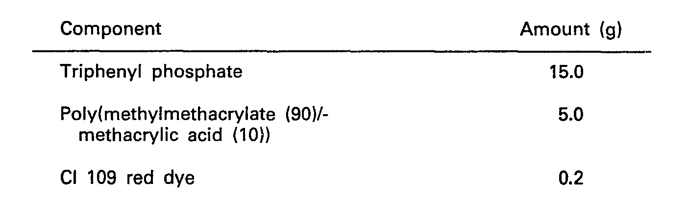
- Using the procedure described in Example 6, the image is transferred to the ceramic substrate and is toned once more with the above toner. The toned, transferred image is then toned as described in Example 6 three times with prolonged tack toner (a) of the above Table followed by one application of prolonged tack toner (b) of the above Table for a total of four separate cycles, i.e., the total toned layers is fifteen. The toned element is fired for one hour in a nitrogen belt type furnace set to reach a peak temperature of 900°C. After cooling, the resistivity is measured as 0.004 to 0.008 ohm/square.
Claims (7)
Applications Claiming Priority (2)
| Application Number | Priority Date | Filing Date | Title |
|---|---|---|---|
| US06/124,606 US4469625A (en) | 1980-02-25 | 1980-02-25 | Prolonged tack toners for the preparation of electric circuits |
| US124606 | 2008-04-18 |
Publications (3)
| Publication Number | Publication Date |
|---|---|
| EP0035187A2 EP0035187A2 (en) | 1981-09-09 |
| EP0035187A3 EP0035187A3 (en) | 1982-09-29 |
| EP0035187B1 true EP0035187B1 (en) | 1985-06-19 |
Family
ID=22415835
Family Applications (1)
| Application Number | Title | Priority Date | Filing Date |
|---|---|---|---|
| EP81101206A Expired EP0035187B1 (en) | 1980-02-25 | 1981-02-20 | Prolonged tack toners for the preparation of electric circuits |
Country Status (7)
| Country | Link |
|---|---|
| US (1) | US4469625A (en) |
| EP (1) | EP0035187B1 (en) |
| JP (1) | JPS56135846A (en) |
| CA (1) | CA1154993A (en) |
| DE (1) | DE3170976D1 (en) |
| DK (1) | DK81981A (en) |
| IE (1) | IE50735B1 (en) |
Cited By (1)
| Publication number | Priority date | Publication date | Assignee | Title |
|---|---|---|---|---|
| US6110632A (en) * | 1996-07-10 | 2000-08-29 | Cookson Matthey Ceramics Plc | Toner containing inorganic ceramic color |
Families Citing this family (17)
| Publication number | Priority date | Publication date | Assignee | Title |
|---|---|---|---|---|
| US4623389A (en) * | 1985-04-22 | 1986-11-18 | Ppg Industries, Inc. | Electroconductive silver composition |
| JPS62288820A (en) * | 1986-06-07 | 1987-12-15 | Iic Kagaku Kogyo Kk | Image forming method |
| DE3913115A1 (en) * | 1989-04-21 | 1990-10-25 | Du Pont Deutschland | METHOD FOR PRODUCING ELECTRICALLY CONDUCTIVE PATTERNS |
| DE3913116C1 (en) * | 1989-04-21 | 1990-11-08 | Du Pont De Nemours (Deutschland) Gmbh, 6380 Bad Homburg, De | |
| DE3913117A1 (en) * | 1989-04-21 | 1990-10-25 | Du Pont Deutschland | METHOD FOR PRODUCING ELECTRICALLY CONDUCTIVE PATTERNS |
| JP2962776B2 (en) * | 1989-08-31 | 1999-10-12 | 大日本印刷株式会社 | Composition for forming conductive pattern and method for forming conductive pattern |
| US5039588A (en) * | 1989-10-16 | 1991-08-13 | E. I. Du Pont De Nemours And Company | Non-electroscopic prolonged tack toners |
| US5240814A (en) * | 1991-02-27 | 1993-08-31 | E. I. Du Pont De Nemours And Company | Curable, heat activatable transfer toners |
| US5219702A (en) * | 1991-02-27 | 1993-06-15 | E. I. Du Pont De Nemours And Company | Process for detackifying transferred toned images |
| US5275918A (en) * | 1991-02-27 | 1994-01-04 | E. I. Du Pont De Nemours And Company | Ultraviolet curable heat activatable transfer toners |
| US5250387A (en) * | 1992-01-29 | 1993-10-05 | E. I. Du Pont De Nemours And Company | Transfer process using ultraviolet curable, non-prolonged tack toning materials |
| EP1783558B1 (en) * | 2004-07-09 | 2013-09-11 | Asahi Glass Company, Limited | Conductive toner and process for producing glass plate with conductive printed wire |
| US7892715B2 (en) | 2005-10-05 | 2011-02-22 | Asahi Glass Company, Limited | Color toner having inorganic pigment particles, glass frit, and heat decomposable binder for making a ceramic color print |
| CN101454255A (en) * | 2006-05-30 | 2009-06-10 | 旭硝子株式会社 | Production method of glass plate with conductive printed wire and glass plate with conductive printed wire |
| EP2232629A1 (en) * | 2007-12-22 | 2010-09-29 | Eastman Kodak Company | A method for producing an antenna structure for an rfid device, and a dry toner for use in producing such antenna structure |
| WO2013025209A1 (en) * | 2011-08-17 | 2013-02-21 | Eastman Kodak Company | Electrophotographic printing of electrical conductors |
| FR3090208B1 (en) | 2018-12-18 | 2021-01-15 | Commissariat Energie Atomique | ELECTROMECHANICAL MICROSYSTEM INCLUDING AN ACTIVE ELEMENT PROVIDED WITH A STRUCTURED CORE LAYER |
Family Cites Families (15)
| Publication number | Priority date | Publication date | Assignee | Title |
|---|---|---|---|---|
| US2608542A (en) * | 1950-09-26 | 1952-08-26 | Warren S D Co | Heat-energizable adhesives and coated products and process of making same |
| NL132290C (en) * | 1959-09-11 | |||
| US3293072A (en) * | 1961-06-29 | 1966-12-20 | Vitta Corp | Ceramic-metallizing tape |
| US3350341A (en) * | 1964-07-16 | 1967-10-31 | Du Pont | Silver compositions containing novel vitreous binders and a vehicle |
| US3537892A (en) * | 1966-11-29 | 1970-11-03 | Ibm | Metallizing composition conductor and method |
| US3762944A (en) * | 1969-10-02 | 1973-10-02 | Dennison Mfg Co | Electrothermographic duplicating sheet and process |
| US3830651A (en) * | 1970-05-25 | 1974-08-20 | Owens Illinois Inc | Fine line electronic micro-circuitry printing pastes |
| US3746568A (en) * | 1971-03-11 | 1973-07-17 | Owens Illinois Inc | Noble metal glass binder compositions and methods of using same |
| US3939085A (en) * | 1971-06-21 | 1976-02-17 | Savin Business Machines Corporation | Process for forming a liquid developer organisol |
| DE2254477C2 (en) * | 1971-11-08 | 1982-04-08 | Owens-Illinois, Inc., 43666 Toledo, Ohio | Process for applying and adhesive bonding of electrical conductor material to a substrate and printing compound for carrying out the process |
| JPS5913027B2 (en) * | 1975-11-26 | 1984-03-27 | 株式会社リコー | Fukushimai Fukushiyahouhou |
| CA1097495A (en) * | 1976-05-24 | 1981-03-17 | James H. Aumiller | Electrically conductive adhesive |
| US4220698A (en) * | 1978-12-20 | 1980-09-02 | Reprographic Materials, Inc. | Direct imaging pressure fixable magnetic toners |
| US4303698A (en) * | 1980-02-25 | 1981-12-01 | E. I. Du Pont De Nemours And Company | Use of prolonged tack toners for the preparation of electric circuits |
| US4654174A (en) * | 1982-05-28 | 1987-03-31 | The Dow Chemical Company | Preparation of aliphatic anhydrides and alkylidene dicarboxylates from divinyl ethers and carboxylic acids |
-
1980
- 1980-02-25 US US06/124,606 patent/US4469625A/en not_active Expired - Lifetime
-
1981
- 1981-02-19 CA CA000371287A patent/CA1154993A/en not_active Expired
- 1981-02-20 EP EP81101206A patent/EP0035187B1/en not_active Expired
- 1981-02-20 DE DE8181101206T patent/DE3170976D1/en not_active Expired
- 1981-02-24 IE IE370/81A patent/IE50735B1/en unknown
- 1981-02-24 DK DK81981A patent/DK81981A/en not_active Application Discontinuation
- 1981-02-25 JP JP2758981A patent/JPS56135846A/en active Granted
Cited By (1)
| Publication number | Priority date | Publication date | Assignee | Title |
|---|---|---|---|---|
| US6110632A (en) * | 1996-07-10 | 2000-08-29 | Cookson Matthey Ceramics Plc | Toner containing inorganic ceramic color |
Also Published As
| Publication number | Publication date |
|---|---|
| DK81981A (en) | 1981-08-26 |
| IE810370L (en) | 1981-08-25 |
| IE50735B1 (en) | 1986-06-25 |
| JPH039564B2 (en) | 1991-02-08 |
| EP0035187A2 (en) | 1981-09-09 |
| CA1154993A (en) | 1983-10-11 |
| US4469625A (en) | 1984-09-04 |
| EP0035187A3 (en) | 1982-09-29 |
| DE3170976D1 (en) | 1985-07-25 |
| JPS56135846A (en) | 1981-10-23 |
Similar Documents
| Publication | Publication Date | Title |
|---|---|---|
| US4469625A (en) | Prolonged tack toners for the preparation of electric circuits | |
| US4303698A (en) | Use of prolonged tack toners for the preparation of electric circuits | |
| TW214628B (en) | Photoenhanced diffusion patterning for organic polymer films | |
| EP0751434A2 (en) | Method of forming colored image by use of inorganic toner, inorganic toner for developing latent electrostatic image, and colored toner image bearing image transfer medium | |
| US5624782A (en) | Method of manufacturing thick-film resistor elements | |
| US2735784A (en) | Process of electrostatic printing | |
| WO2000029208A1 (en) | Electrically heatable, transparent windows and mirrors and method for production | |
| US4355055A (en) | Use of prolonged tack toners for the preparation of multilayer electric circuits | |
| EP1798597A2 (en) | Cationically polymerizable photoimageable thick film compositions, electrodes, and methods of forming thereof | |
| US4338391A (en) | Magnetic resist printing process, composition and apparatus | |
| US20110091694A1 (en) | Method for forming fine electrode patterns | |
| US3460476A (en) | Imaging process | |
| US3441505A (en) | Developing powder | |
| US3830648A (en) | Photoconductor-glass binder plate with insulating resin in pores | |
| JP4207241B2 (en) | Chargeable powder for circuit formation and multilayer wiring board using the same | |
| JPH02148881A (en) | Method of forming dielectric layer | |
| US5039588A (en) | Non-electroscopic prolonged tack toners | |
| EP0034816B1 (en) | Multiple transfer of tacky image areas using prolonged tack toners | |
| EP0501397A1 (en) | Curable, heatactivatable transfer toners | |
| US5219702A (en) | Process for detackifying transferred toned images | |
| CN1139821A (en) | Method of manufacturing thick-film resistor | |
| EP0140971B1 (en) | Permanent color photographic picture | |
| JP3897217B2 (en) | Transfer sheet, transfer sheet having toner image, and toner image printing method on heat-resistant solid surface using the same | |
| CA2015093A1 (en) | Process for making electrically conductive patterns | |
| JPH03101292A (en) | Method of making electrically conductive pattern |
Legal Events
| Date | Code | Title | Description |
|---|---|---|---|
| PUAI | Public reference made under article 153(3) epc to a published international application that has entered the european phase |
Free format text: ORIGINAL CODE: 0009012 |
|
| AK | Designated contracting states |
Designated state(s): BE DE FR GB IT LU NL |
|
| PUAL | Search report despatched |
Free format text: ORIGINAL CODE: 0009013 |
|
| AK | Designated contracting states |
Designated state(s): BE DE FR GB IT LU NL |
|
| 17P | Request for examination filed |
Effective date: 19820917 |
|
| ITF | It: translation for a ep patent filed | ||
| GRAA | (expected) grant |
Free format text: ORIGINAL CODE: 0009210 |
|
| AK | Designated contracting states |
Designated state(s): BE DE FR GB IT LU NL |
|
| REF | Corresponds to: |
Ref document number: 3170976 Country of ref document: DE Date of ref document: 19850725 |
|
| ET | Fr: translation filed | ||
| PG25 | Lapsed in a contracting state [announced via postgrant information from national office to epo] |
Ref country code: LU Free format text: LAPSE BECAUSE OF NON-PAYMENT OF DUE FEES Effective date: 19860228 |
|
| PLBE | No opposition filed within time limit |
Free format text: ORIGINAL CODE: 0009261 |
|
| STAA | Information on the status of an ep patent application or granted ep patent |
Free format text: STATUS: NO OPPOSITION FILED WITHIN TIME LIMIT |
|
| 26N | No opposition filed | ||
| PGFP | Annual fee paid to national office [announced via postgrant information from national office to epo] |
Ref country code: BE Payment date: 19901221 Year of fee payment: 11 |
|
| PGFP | Annual fee paid to national office [announced via postgrant information from national office to epo] |
Ref country code: LU Payment date: 19901224 Year of fee payment: 11 |
|
| ITTA | It: last paid annual fee | ||
| EPTA | Lu: last paid annual fee | ||
| PG25 | Lapsed in a contracting state [announced via postgrant information from national office to epo] |
Ref country code: BE Effective date: 19920228 |
|
| BERE | Be: lapsed |
Owner name: E.I. DU PONT DE NEMOURS AND CY Effective date: 19920228 |
|
| PGFP | Annual fee paid to national office [announced via postgrant information from national office to epo] |
Ref country code: FR Payment date: 19921210 Year of fee payment: 13 |
|
| PGFP | Annual fee paid to national office [announced via postgrant information from national office to epo] |
Ref country code: GB Payment date: 19921223 Year of fee payment: 13 |
|
| PGFP | Annual fee paid to national office [announced via postgrant information from national office to epo] |
Ref country code: NL Payment date: 19930228 Year of fee payment: 13 |
|
| PGFP | Annual fee paid to national office [announced via postgrant information from national office to epo] |
Ref country code: DE Payment date: 19931218 Year of fee payment: 14 |
|
| PG25 | Lapsed in a contracting state [announced via postgrant information from national office to epo] |
Ref country code: GB Effective date: 19940220 |
|
| PG25 | Lapsed in a contracting state [announced via postgrant information from national office to epo] |
Ref country code: NL Effective date: 19940901 |
|
| NLV4 | Nl: lapsed or anulled due to non-payment of the annual fee | ||
| GBPC | Gb: european patent ceased through non-payment of renewal fee |
Effective date: 19940220 |
|
| PG25 | Lapsed in a contracting state [announced via postgrant information from national office to epo] |
Ref country code: FR Effective date: 19941031 |
|
| REG | Reference to a national code |
Ref country code: FR Ref legal event code: ST |
|
| PG25 | Lapsed in a contracting state [announced via postgrant information from national office to epo] |
Ref country code: DE Effective date: 19951101 |