EP0034955A1 - Ignition coil for internal-combustion engines - Google Patents
Ignition coil for internal-combustion engines Download PDFInfo
- Publication number
- EP0034955A1 EP0034955A1 EP81400073A EP81400073A EP0034955A1 EP 0034955 A1 EP0034955 A1 EP 0034955A1 EP 81400073 A EP81400073 A EP 81400073A EP 81400073 A EP81400073 A EP 81400073A EP 0034955 A1 EP0034955 A1 EP 0034955A1
- Authority
- EP
- European Patent Office
- Prior art keywords
- branch
- permanent magnet
- ignition coil
- branches
- circuit
- Prior art date
- Legal status (The legal status is an assumption and is not a legal conclusion. Google has not performed a legal analysis and makes no representation as to the accuracy of the status listed.)
- Granted
Links
Images

Classifications
-
- H—ELECTRICITY
- H01—ELECTRIC ELEMENTS
- H01F—MAGNETS; INDUCTANCES; TRANSFORMERS; SELECTION OF MATERIALS FOR THEIR MAGNETIC PROPERTIES
- H01F3/00—Cores, Yokes, or armatures
- H01F3/10—Composite arrangements of magnetic circuits
-
- H—ELECTRICITY
- H01—ELECTRIC ELEMENTS
- H01F—MAGNETS; INDUCTANCES; TRANSFORMERS; SELECTION OF MATERIALS FOR THEIR MAGNETIC PROPERTIES
- H01F29/00—Variable transformers or inductances not covered by group H01F21/00
- H01F29/14—Variable transformers or inductances not covered by group H01F21/00 with variable magnetic bias
- H01F29/146—Constructional details
-
- H—ELECTRICITY
- H01—ELECTRIC ELEMENTS
- H01F—MAGNETS; INDUCTANCES; TRANSFORMERS; SELECTION OF MATERIALS FOR THEIR MAGNETIC PROPERTIES
- H01F38/00—Adaptations of transformers or inductances for specific applications or functions
- H01F38/12—Ignition, e.g. for IC engines
Definitions
- the present invention relates to an ignition coil for an internal combustion engine, in particular for a motor vehicle, coil comprising a closed magnetic circuit made up of a plurality of sheets, magnetic circuit in which is arranged in one of the permanent branches, a winding primary and a secondary winding surrounding another of the branches.
- a closed magnetic circuit made up of a plurality of sheets, magnetic circuit in which is arranged in one of the permanent branches, a winding primary and a secondary winding surrounding another of the branches.
- An embodiment of a coil with a closed magnetic circuit is known, embodiment, in which a permanent magnet is arranged perpendicular to the flux flowing in the circuit, the permanent magnet being magnetized in the direction of its thickness so that the the magnetic flux it generates is opposite to the flux produced by the primary winding when it is supplied.
- This permanent magnet is located in the branch opposite to the branch surrounded by the primary and secondary windings.
- One of the drawbacks of this circuit consisting of two U-shaped parts arranged facing each other, is that the dimensions of the permanent magnet, apart from its thickness, are a function of the section of the magnetic circuit.
- This quality which is involved in the reluctance of the circuit is dependent on the differences in thickness of the permanent magnet disposed opposite the branch surrounding the windings, which differences in thickness are inherent in any mass production.
- an ignition coil comprising a magnetic circuit, consisting of a plurality of sheets, and a permanent magnet disposed in one of the branches of said circuit, characterized in that that said circuit comprises, at least, a magnetic seal disposed along a plane forming an acute angle ⁇ with the plane of the faces of the permanent magnet adjacent to said circuit.
- the branch on which the primary winding and the secondary winding are arranged is of thickness less than the thickness of the other branches of the magnetic circuit.
- At least one magnetic seal is placed at one end of the branch surrounded by the primary and secondary windings.
- a fraction of the sheets, constituting the half-branches covers on both sides of the windings, the ends of the branch on which the windings are arranged.
- a magnetic circuit of this kind is known, in particular, from French patent application No. 72,02568 of 26.1.1972.
- a second embodiment of the ignition coil according to the invention is characterized in that one of the half-branches, constituting the branch in which the magnet is arranged, is provided at one of its ends, d 'A spoiler whose depth creates an air gap E, of predetermined value, between the two half-branches, which air gap E is located in the extension of the permanent magnet at one of its faces.
- Said circuif is also characterized in that another air gap E ', of predetermined value, is created between the edge of the sheets which constitute the small base of the rectangular trapezium of the portion of one of the half-branches adjacent to the permanent magnet and the song of the sheets of the other half-branch.
- a primary winding 4 and a secondary winding 5 surround the branch 6 which branch 6 is in this embodiment, consisting of a fraction of the sheets constituting the half-branch 3a, forming with the half-branch 3 ⁇ the branch 3.
- the thickness E ′ of branch 6 (see FIG. 2) is, in this embodiment less than twice the thickness E of branch 3.
- a magnetic seal 7 (see Figure 1) is provided at one end of the branch 6, which seal 7 is arranged in a plane forming an acute angle ⁇ with the plane of the adjacent faces 2a and 2b of the permanent magnet 2 to the half branches 3a and 3b.
- the half-branches 3a and 3b are made up of sheets of unequal lengths, so that a fraction of these sheets covers, on either side of the primary 4 and secondary 5 windings, the ends of the branch 6.
- this magnetic circuit eliminates the drawbacks cited in the prior art, by the fact that a large surface permanent magnet is provided in a magnetic circuit whose weight and size have been reduced to a minimum, compatible with the performance of the ignition coil.
- the large thickness E of the half-branches in which the permanent magnet is placed allows a significant reduction in the perimeter of the magnetic circuit and, correspondingly, a reduced size of the ignition coil.
- the magnetic seal located at one end of the branch surrounded by the primary and secondary windings, and forming an acute angle ⁇ with the plane of the faces adjacent to the permanent magnet absorbs the thickness differences of the permanent magnet due to manufacturing tolerances and also the cutting tolerances of the sheets constituting the magnetic circuit.
- This first embodiment has the drawback, however, that the flow reversal created in the branch surrounded by the primary and secondary windings by the current flowing in the primary winding requires the use of a magnet having a very coercive field. high so as to avoid demagnetization when the flux is reversed.
- the second embodiment of the magnetic circuit according to the invention aims to remedy this drawback.
- an air gap E of predetermined value is created between the half-branch 3a and the half-branch 3b by a spoiler 3c forming a projection at one of the ends of the half-branch 3b.
- the air gap E is located in the extension of the magnet 2 at its face 2b,
- Another air gap E ' is created between the edge of the sheets, of the half-branch 3b, constituting the small base 3d, of the portion, of said half-branch, having a view from above of the appearance d 'a rectangular trapezoid and the third song of the sheets of the half-branch 3a.
- the ignition coil may, depending on the performance required, such as for example a strong choke, have a magnetic circuit comprising either the air gap E or the air gap E ', or else comprise both the air gaps E and E'.
- the particular configuration of the magnetic circuit, according to this second embodiment ensures that despite the use for reasons of economy and supply, permanent magnets of large surface area and low coercive field, the weight and size of the ignition coil have been reduced to the maximum compatible with the required performance.
Abstract
Description
La présente invention concerne une bobine d'allumage pour moteur à combustion interne, notamment de véhicule automobile, bobine comportant un circuit magnétique fermé constitué d'une pluralité de tôles, circuit magnétique dans lequel est disposé dans l'une des branches permanent, un enroulement primaire et un enroulement secondaire entourant une autre des branches. De telles bobines travaillant sur une grande partie du cycle d'hystérésis du circuit magnétique apportent une amélioration notable des caractéristiques par rapport aux bobines classiques a circuit ouvert qui n'utilisent qu'une portion du cycle. On connait un mode de réalisation d'une bobine à circuit magnétique fermé, mode de réalisation,dans lequel un aimant permanent est disposé perpendiculairement au flux circulant dans le circuit, l'aimant permanent étant aimanté dans le sens de son épaisseur de façon que le flux magnétique qu'il engendre soit opposé au flux produit par l'enroulement primaire lorsqu'il est alimenté. Cet aimant permanent est situé dans la branche opposée à la branche entourée par les enroulements primaire et secondaire. L'un des inconvénients de ce circuit, constitué de deux pièces en forme de U disposées en regard, est que les dimensions de l'aimant permanent, hormis son épaisseur, sont fonction de la section du circuit magnétique. Ceci implique que tout accroissement du volume de l'aimant, dans le but de disposer d'un champ magnétique,de l'aimant, plus important conduit à un accroissement de la section du circuit donc à un accroissement de poids et de coût. Un autre inconvénient de ce circuit est que les performances de la bobine sont conditionnées en partie, par la qualité du joint magnétique situé au centre de la branche entourée des enroulements primaire et secondaire et parallèlement au plan de joint aimant permanent-circuit magnétique.The present invention relates to an ignition coil for an internal combustion engine, in particular for a motor vehicle, coil comprising a closed magnetic circuit made up of a plurality of sheets, magnetic circuit in which is arranged in one of the permanent branches, a winding primary and a secondary winding surrounding another of the branches. Such coils working on a large part of the hysteresis cycle of the magnetic circuit provide a significant improvement in characteristics compared to conventional open circuit coils which use only a portion of the cycle. An embodiment of a coil with a closed magnetic circuit is known, embodiment, in which a permanent magnet is arranged perpendicular to the flux flowing in the circuit, the permanent magnet being magnetized in the direction of its thickness so that the the magnetic flux it generates is opposite to the flux produced by the primary winding when it is supplied. This permanent magnet is located in the branch opposite to the branch surrounded by the primary and secondary windings. One of the drawbacks of this circuit, consisting of two U-shaped parts arranged facing each other, is that the dimensions of the permanent magnet, apart from its thickness, are a function of the section of the magnetic circuit. This implies that any increase in the volume of the magnet, with the aim of having a magnetic field, of the magnet, which is greater, leads to an increase in the section of the circuit, therefore to an increase in weight and cost. Another drawback of this circuit is that the performance of the coil is conditioned in part by the quality of the magnetic seal located in the center of the branch surrounded by the primary and secondary windings and parallel to the plane of the permanent magnet-magnetic circuit joint.
Cette qualité qui intervient dans la réluctance du circuit est dépendante des différences d'épaisseur de l'aimant permanent disposé à l'opposé de la branche entourant les enroulements, lesquelles différences d'épaisseur sont inhérentes à toute fabrication de grande série.This quality which is involved in the reluctance of the circuit is dependent on the differences in thickness of the permanent magnet disposed opposite the branch surrounding the windings, which differences in thickness are inherent in any mass production.
Dans ce mode de réalisation pour pallier cet inconvénient, des éléments ferro-magnétiques chevauchant ledit joint sont appliqués contre les pièces en U, mais ceci conduit à un accroissement du poids du cuivre constituant les enroulements, en raison du fait que l'on accroit ainsi la section de la branche sur laquelle sont disposés les enroulements. La présente invention a pour but de remédier à ces inconvénients et concerne à cet effet une bobine d'allumage comportant un circuit magnétique, constitué d'une pluralité de tôles, et un aimant permanent disposé dans l'une des branchesdudit circuit, caractérisée en ce que ledit circuit comporte, au moins, un joint magnétique disposé selon un plan formant un angle aigu α avec le plan des faces de l'aimant permanent adjacentes audit circuit. Selon l'invention la branche sur laquelle sont disposés l'enroulement primaire et l'enroulement secondaire est d'épaisseur inférieure à l'épaisseur des autres branches du circuit magnétique. Au moins un joint magnétique est disposé à l'une des extrémités de la branche entourée des enroulements primaire et secondaire. Une fraction des tôles, constituant les demi-branches recouvre de part et d'autre des enroulements, les extrémités de la branche sur laquelle sont disposés les enroulements. Ce circuit magnétique qui correspond à un premier mode de réalisation de l'invention présente toutefois l'inconvénient que l'inversion de flux créée, dans la branche entourée des enroulements primaire et secondaire, par le courant circulant dans l'enroulement primaire nécessite l'utilisation d'un aimant ayant un champ-coercitif très élevé de manière à éviter la désaimantation lors de l'inversion du flux.In this embodiment to overcome this drawback, ferromagnetic elements overlapping said seal are applied against the U-shaped parts, but this leads to an increase in the weight of the copper constituting the windings, due to the fact that the section of the branch on which the windings are arranged is thus increased. The present invention aims to remedy these drawbacks and for this purpose relates to an ignition coil comprising a magnetic circuit, consisting of a plurality of sheets, and a permanent magnet disposed in one of the branches of said circuit, characterized in that that said circuit comprises, at least, a magnetic seal disposed along a plane forming an acute angle α with the plane of the faces of the permanent magnet adjacent to said circuit. According to the invention, the branch on which the primary winding and the secondary winding are arranged is of thickness less than the thickness of the other branches of the magnetic circuit. At least one magnetic seal is placed at one end of the branch surrounded by the primary and secondary windings. A fraction of the sheets, constituting the half-branches covers on both sides of the windings, the ends of the branch on which the windings are arranged. This magnetic circuit which corresponds to a first embodiment of the invention has the drawback, however, that the flow reversal created in the branch surrounded by the primary and secondary windings by the current flowing in the primary winding requires the use of a magnet having a very high coercive field so as to avoid demagnetization during the reversal of the flux.
Ce genre d'aimant est coûteux et peu disponible à ce jour, ce qui n'est pas compatible avec une fabrication de grande série. Ceci conduit à l'utilisation d'aimants de grande diffusion dont le champ coercitif est faible, par rapport aux aimants cités ci-dessus, et ne permet pas en conséquence, l'inversion de flux au niveau de l'aimant sans désaimantation importante et éventuellement totale dudit aimant. Il devient donc nécessaire de prévoir, dans le circuit magnétique, une portion faiblement reluctante, laquelle portion est disposée en dérivation par rapport aux parties recevant le flux de l'aimant de manière que l'inversion de flux se produise au niveau de la branche, du circuit, entourée des enroulements primaire et secondaire et non au niveau de l'aimant.This kind of magnet is expensive and not very available to date, which is not compatible with mass production. This leads to the use of magnets of large diffusion whose coercive field is weak, compared to the magnets mentioned above, and does not consequently allow, the reversal of flux at the level of the magnet without significant demagnetization and possibly total of said magnet. It therefore becomes necessary to provide, in the magnetic circuit, a weakly reluctant portion, which portion is arranged as a bypass with respect to the parts receiving the flux from the magnet so that the reversal of flux occurs at the branch level, of the circuit, surrounded by the primary and secondary windings and not at the level of the magnet.
Un circuit magnétique de ce genre est connu, notamment, par la demande de brevet français n°72 02568 du 26.1.1972.A magnetic circuit of this kind is known, in particular, from French patent application No. 72,02568 of 26.1.1972.
Mais sa conception présente l'inconvénient d'avoir un encombrement, et conséquemment un poids, trop important en raison du fait que la portion de déviation du flux produit par l'enroulement primaire constitue en réalité un circuit indépendant.However, its design has the drawback of having a space requirement, and consequently a weight, which is too large due to the fact that the portion of deflection of the flux produced by the primary winding actually constitutes an independent circuit.
Un deuxième mode de réalisation de la bobine d'allumage selon l'invention est caractérisé en ce que l'une des demi-branches, constituant la branche dans laquelle est disposé l'aimant, est munie à l'une de ses extrémités, d'un becquet dont la profondeur crée un entrefer E, de valeur prédéterminée, entre les deux demi-branches, lequel entrefer E est situé dans le prolongement de l'aimant permanent au niveau de l'une de ses faces.A second embodiment of the ignition coil according to the invention is characterized in that one of the half-branches, constituting the branch in which the magnet is arranged, is provided at one of its ends, d 'A spoiler whose depth creates an air gap E, of predetermined value, between the two half-branches, which air gap E is located in the extension of the permanent magnet at one of its faces.
Ledit circuif est egalement caractérisé en ce qu'un autre entrefer E', de valeur prédéterminée, est créé entre le chant des tôles qui constituent la petite base du trapéze rectangle de la portion d'une des demi-branches adjacentes à l'aimant permanent et le chant des tôles de l'autre demi-branche.Said circuif is also characterized in that another air gap E ', of predetermined value, is created between the edge of the sheets which constitute the small base of the rectangular trapezium of the portion of one of the half-branches adjacent to the permanent magnet and the song of the sheets of the other half-branch.
La description qui va suivre en regard des dessins annexés, donnés à titre d'exemple non limitatif, fera mieux comprendre comment l'invention peut être réalisée.The description which follows with reference to the appended drawings, given by way of nonlimiting example, will make it easier to understand how the invention can be implemented.
- La figure 1 est une vue de dessus en coupe partielle d'une bobine d'allumage selon un premier mode de réalisation de l'invention.Figure 1 is a top view in partial section of an ignition coil according to a first embodiment of the invention.
- La figure 2 est une vue de côté de cette bobine.Figure 2 is a side view of this coil.
-
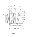
La figure 3 est une vue de dessus en coupe partielle d'une bobine d'allumage selon un deuxième mode de réalisation de l'invention. Selon un premier mode de réalisation, la bobine d'allumage selon l'invention (voir figure 1) comporte un circuit magnétique fermé 1, constitué d'une pluralité de tôles. Un aimant permanent 2, aimanté dans le sens de son épaisseur est disposé dans une branche 3 dudit circuit 1.Figure 3 is a top view in partial section of an ignition coil according to a second embodiment of the invention. According to a first embodiment, the ignition coil according to the invention (see FIG. 1) comprises a closed magnetic circuit 1, made up of a plurality of sheets. A
permanent magnet 2, magnetized in the direction of its thickness, is placed in abranch 3 of said circuit 1.
Un enroulement primaire 4 et un enroulement secondaire 5 entourent la branche 6 laquelle branche 6 est dans cet exemple de réalisation, constituéed'une fraction des tôles constituant la demi- branche 3a, formant avec la demi-branche 3þ la branche 3. L'épaisseur E' de la branche 6 (voir figure 2) est, dans cet exemple de réalisation inférieure de deux fois environ à l'épaisseur E de la branche 3.A
Un joint magnétique 7 (voir figure 1) est prévu à l'une des extrémités de la branche 6, lequel joint 7 est disposé selon un plan formant un angle aigu α avec le plan des faces 2a et 2b de l'aimant permanent 2 adjacentes aux demi-branches 3a et 3b.A magnetic seal 7 (see Figure 1) is provided at one end of the
Conformément à l'invention les demi-branches 3a et 3b sont constituées de tôles d'inégales longueurs de, manière qu'une fraction de ces tôles recouvre, de part et d'autre des enroulements primaire 4 et secondaire 5, les extrémités de la branche 6.According to the invention, the half-
De par sa configuration particulière, telle que l'on vient de la décrire, ce circuit magnétique permet d'éliminer les inconvénients cités de l'art antérieur, par le fait qu'il est prévu un aimant permanent de grande surface dans un circuit magnétique dont le poids et l'encombrement ont été réduits au maximum, compatibles avec les performances de la bobine d'allumage.Due to its particular configuration, as just described, this magnetic circuit eliminates the drawbacks cited in the prior art, by the fact that a large surface permanent magnet is provided in a magnetic circuit whose weight and size have been reduced to a minimum, compatible with the performance of the ignition coil.
D'autre part la forte épaisseur E des demi-branches dans lesquelles est disposé l'aimant permanent autorise une réduction importante du périmètre du circuit magnétique et corrélativement un encombrement réduit de la bobine d'allumage.On the other hand, the large thickness E of the half-branches in which the permanent magnet is placed allows a significant reduction in the perimeter of the magnetic circuit and, correspondingly, a reduced size of the ignition coil.
De môme il n'y a plus dépendance entre les dimensions de l'aimant et les dimensions de la branche entourée par les enroulements primaire et secondaire.Similarly, there is no longer any dependence between the dimensions of the magnet and the dimensions of the branch surrounded by the primary and secondary windings.
Enfin le joint magnétique situé à l'une des extrémités de la branche entourée par les enroulements primaire et secondaire, et formant un angle aigus α avec le plan des faces addjacentes à l'aimant permanent absorbe les différences d'épaisseur de l'aimant permanent dues aux tolérances de fabrication et également les tolérances de découpage des tôles constituant le circuit magnétique.Finally the magnetic seal located at one end of the branch surrounded by the primary and secondary windings, and forming an acute angle α with the plane of the faces adjacent to the permanent magnet absorbs the thickness differences of the permanent magnet due to manufacturing tolerances and also the cutting tolerances of the sheets constituting the magnetic circuit.
Ce premier mode de réalisation présente toutefois l'inconvénient que l'inversion de flux créée, dans la branche entourée des enroulements primaire et secondaire, par le courant circulant dans l'enroulement primaire nécessite l'utilisation d'un aimant ayant un champ coercitif très élevé de manière à éviter la désaimantation lors de l'inversion du flux.This first embodiment has the drawback, however, that the flow reversal created in the branch surrounded by the primary and secondary windings by the current flowing in the primary winding requires the use of a magnet having a very coercive field. high so as to avoid demagnetization when the flux is reversed.
Ce genre d'aimant est coûteux et peu disponible à ce jour, ce qui n'est pas compatible avec une fabrication de grande série. Ceci conduit à l'utilisation d'aimants de grande diffusion dont le champ coercitif est faible, par rapport aux aimants cités ci-dessus, et ne permet pas en conséquence, l'inversion de flux au niveau de l'aimant sans désaimantation importante et éventuellement totale dudit aimant.This type of magnet is expensive and not very available to date, which is not compatible with mass production. This leads to the use of magnets of large diffusion whose coercive field is weak, compared to the magnets mentioned above, and does not consequently allow, the reversal of flux at the level of the magnet without significant demagnetization and possibly total of said magnet.
Le deuxième mode de réalisation du circuit magnétique selon l'invention, a pour but de remédier à cet inconvénient.The second embodiment of the magnetic circuit according to the invention aims to remedy this drawback.
A cet effet un entrefer E, de valeur prédéterminée est créé entre la demi-branche 3a et la demi-branche 3b par un becquet 3c formant une saillie à l'une des extrémités de la demi-branche 3b. L'entrefer E est situé dans le pxolongement de l'aimant 2 au niveau de sa face 2b,For this purpose an air gap E, of predetermined value is created between the half-
Un autre entrefer E', de valeur prédéterminée, est créé entre le chant des tôles, de la demi-branche 3b, constituant la petite base 3d, de la portion, de ladite demi-branche, ayant en vue de dessus l'allure d'un trapèze rectangle et le chant 3e des tôles de la demi-branche 3a.Another air gap E ', of predetermined value, is created between the edge of the sheets, of the half-
La bobine d'allumage peut suivant les performances exigées, telle par exemple qu'une forte self, avoir un circuit magnétique comportant soit l'entrefer E ou l'entrefer E', ou bien comporter à la fois les entrefers E et E'.The ignition coil may, depending on the performance required, such as for example a strong choke, have a magnetic circuit comprising either the air gap E or the air gap E ', or else comprise both the air gaps E and E'.
La configuration particulière du circuit magnétique, selon ce deuxième mode de réalisation assure que malgré l'emploi pour des raisons d'économie et d'approvisionnement, d'aimants permanents de grande surface et de champ coercitif faible, le poids et l'encombrement de la bobine d'allumage ont été réduits au maximum compatible avec les performances exigées.The particular configuration of the magnetic circuit, according to this second embodiment ensures that despite the use for reasons of economy and supply, permanent magnets of large surface area and low coercive field, the weight and size of the ignition coil have been reduced to the maximum compatible with the required performance.
Claims (8)
Applications Claiming Priority (4)
| Application Number | Priority Date | Filing Date | Title |
|---|---|---|---|
| FR8003653 | 1980-02-20 | ||
| FR8003653A FR2476218A1 (en) | 1980-02-20 | 1980-02-20 | IC engine ignition coil winding - is on magnetic circuit branch with junction inclined at angle to permanent magnet |
| FR8009742 | 1980-04-30 | ||
| FR8009742A FR2481753A2 (en) | 1980-04-30 | 1980-04-30 | IC engine ignition coil winding - is on magnetic circuit branch with junction inclined at angle to permanent magnet |
Publications (2)
| Publication Number | Publication Date |
|---|---|
| EP0034955A1 true EP0034955A1 (en) | 1981-09-02 |
| EP0034955B1 EP0034955B1 (en) | 1984-10-24 |
Family
ID=26221613
Family Applications (1)
| Application Number | Title | Priority Date | Filing Date |
|---|---|---|---|
| EP81400073A Expired EP0034955B1 (en) | 1980-02-20 | 1981-01-21 | Ignition coil for internal-combustion engines |
Country Status (3)
| Country | Link |
|---|---|
| EP (1) | EP0034955B1 (en) |
| DE (1) | DE3166748D1 (en) |
| ES (1) | ES8200744A1 (en) |
Cited By (9)
| Publication number | Priority date | Publication date | Assignee | Title |
|---|---|---|---|---|
| EP0335142A1 (en) * | 1988-03-29 | 1989-10-04 | VOGT electronic Aktiengesellschaft | Transformer for switching network |
| FR2778490A1 (en) * | 1998-05-11 | 1999-11-12 | Sagem | Ignition coil for use with IC engine spark plug |
| EP1174595A1 (en) * | 2000-07-18 | 2002-01-23 | Peugeot Citroen Automobiles SA | Valve actuator for internal combustion engine |
| EP1174596A1 (en) * | 2000-07-20 | 2002-01-23 | Peugeot Citroen Automobiles SA | Electromagnetic valve actuator in an internal combustion engine |
| FR2819623A1 (en) * | 2001-01-17 | 2002-07-19 | Sagem | Internal combustion engine ignition coil having end section with permanent magnet with permanent axis perpendicular magnet with permanent axis centre and having flux return section. |
| DE10159112A1 (en) * | 2001-12-01 | 2003-06-18 | Hella Kg Hueck & Co | Ignition transformer for motor vehicle gas discharge lamp, has permanent magnet located in air-gap of annular core |
| FR2839580A1 (en) * | 2002-05-10 | 2003-11-14 | Johnson Contr Automotive Elect | Car engine ignition coil, has closed magnetic circuit with magnetic gap filled permanent magnet and outer coil with permanent magnet limiting magnetic trajectory/magnetic field effect |
| EP2001028A1 (en) * | 2007-06-08 | 2008-12-10 | ABB Oy | Protection of permanent magnets in a DC-inductor |
| WO2011159406A1 (en) * | 2010-06-15 | 2011-12-22 | Federal-Mogul Ignition Company | Ignition coil with energy storage and transformation |
Citations (1)
| Publication number | Priority date | Publication date | Assignee | Title |
|---|---|---|---|---|
| FR2168919A3 (en) * | 1972-01-26 | 1973-09-07 | Ducellier & Cie |
Family Cites Families (5)
| Publication number | Priority date | Publication date | Assignee | Title |
|---|---|---|---|---|
| BE505464A (en) * | 1951-04-23 | |||
| NL79888C (en) * | 1951-04-23 | |||
| FR66586E (en) * | 1954-06-16 | 1957-04-16 | App Marchal Soc D Expl Const D | Transformer called ignition <<coil>> |
| DE1464202A1 (en) * | 1962-02-23 | 1969-05-22 | Licentia Gmbh | Permanently biased inductive element |
| DE2226289A1 (en) * | 1971-05-11 | 1973-01-04 | Tdk Electronics Co Ltd | PRE-MAGNETIZED MAGNETIC CORE |
-
1981
- 1981-01-21 EP EP81400073A patent/EP0034955B1/en not_active Expired
- 1981-01-21 DE DE8181400073T patent/DE3166748D1/en not_active Expired
- 1981-02-18 ES ES499553A patent/ES8200744A1/en not_active Expired
Patent Citations (1)
| Publication number | Priority date | Publication date | Assignee | Title |
|---|---|---|---|---|
| FR2168919A3 (en) * | 1972-01-26 | 1973-09-07 | Ducellier & Cie |
Cited By (15)
| Publication number | Priority date | Publication date | Assignee | Title |
|---|---|---|---|---|
| EP0335142A1 (en) * | 1988-03-29 | 1989-10-04 | VOGT electronic Aktiengesellschaft | Transformer for switching network |
| FR2778490A1 (en) * | 1998-05-11 | 1999-11-12 | Sagem | Ignition coil for use with IC engine spark plug |
| EP1174595A1 (en) * | 2000-07-18 | 2002-01-23 | Peugeot Citroen Automobiles SA | Valve actuator for internal combustion engine |
| FR2812024A1 (en) * | 2000-07-18 | 2002-01-25 | Peugeot Citroen Automobiles Sa | VALVE ACTUATOR FOR INTERNAL COMBUSTION ENGINES |
| EP1174596A1 (en) * | 2000-07-20 | 2002-01-23 | Peugeot Citroen Automobiles SA | Electromagnetic valve actuator in an internal combustion engine |
| FR2812025A1 (en) * | 2000-07-20 | 2002-01-25 | Peugeot Citroen Automobiles Sa | ELECTROMAGNETIC VALVE ACTUATOR OF INTERNAL COMBUSTION ENGINE |
| FR2819623A1 (en) * | 2001-01-17 | 2002-07-19 | Sagem | Internal combustion engine ignition coil having end section with permanent magnet with permanent axis perpendicular magnet with permanent axis centre and having flux return section. |
| DE10159112A1 (en) * | 2001-12-01 | 2003-06-18 | Hella Kg Hueck & Co | Ignition transformer for motor vehicle gas discharge lamp, has permanent magnet located in air-gap of annular core |
| FR2839580A1 (en) * | 2002-05-10 | 2003-11-14 | Johnson Contr Automotive Elect | Car engine ignition coil, has closed magnetic circuit with magnetic gap filled permanent magnet and outer coil with permanent magnet limiting magnetic trajectory/magnetic field effect |
| EP2001028A1 (en) * | 2007-06-08 | 2008-12-10 | ABB Oy | Protection of permanent magnets in a DC-inductor |
| US8035470B2 (en) | 2007-06-08 | 2011-10-11 | Abb Oy | Protection of permanent magnets in a DC-inductor |
| CN101364472B (en) * | 2007-06-08 | 2011-12-14 | Abb有限公司 | Protection of permanent magnents in a dc-inductor |
| WO2011159406A1 (en) * | 2010-06-15 | 2011-12-22 | Federal-Mogul Ignition Company | Ignition coil with energy storage and transformation |
| US8289117B2 (en) | 2010-06-15 | 2012-10-16 | Federal-Mogul Corporation | Ignition coil with energy storage and transformation |
| CN102939635A (en) * | 2010-06-15 | 2013-02-20 | 费德罗-莫格尔点火公司 | Ignition coil with energy storage and transformation |
Also Published As
| Publication number | Publication date |
|---|---|
| DE3166748D1 (en) | 1984-11-29 |
| EP0034955B1 (en) | 1984-10-24 |
| ES499553A0 (en) | 1981-12-01 |
| ES8200744A1 (en) | 1981-12-01 |
Similar Documents
| Publication | Publication Date | Title |
|---|---|---|
| EP1359657A1 (en) | Electric machine rotor specially adapted to high speeds | |
| EP0034955B1 (en) | Ignition coil for internal-combustion engines | |
| WO1996038904A1 (en) | Electromagnetic actuator magnetically locked into two or more stable positions | |
| EP0118454B1 (en) | Ignition coil for internal combustion engines | |
| EP1001510A1 (en) | Electromagnetic rotary actuator with at least one magnet embedded in soft magnetic material | |
| FR2913142A1 (en) | Hybrid electromagnetic actuator for relay type electrical switch, has routers arranged in manner such that routers are positioned in part between coils and magnet assemblies in position so as to divert part of magnetic field from assemblies | |
| FR2791485A1 (en) | ROTATING MACHINE COMPRISING IMPROVED EXCITATION MEANS | |
| FR2574880A1 (en) | System forming an axial magnetic thrust bearing for a rotating machine | |
| FR2636480A1 (en) | Synchronous motor with permanent magnets | |
| EP0378596B1 (en) | Two-phase or multiphase synchronous electric motor with disk-shaped rotor | |
| CH643680A5 (en) | ELECTRO-MAGNET FOR BRAKE. | |
| EP3229348B1 (en) | Rotor for an electrical machine | |
| FR2476218A1 (en) | IC engine ignition coil winding - is on magnetic circuit branch with junction inclined at angle to permanent magnet | |
| EP0043744B1 (en) | Ignition coil for internal combustion engine | |
| FR2481753A2 (en) | IC engine ignition coil winding - is on magnetic circuit branch with junction inclined at angle to permanent magnet | |
| EP3939151B1 (en) | Electromagnetic device | |
| EP0072266B1 (en) | Method of obtaining a coil with a closed magnetic circuit and a permanent magnet for the ignition of combustion engines | |
| FR2695267A1 (en) | Stator for electric motor used as starter motor for internal combustion engine - has interior inductor poles in body of stacks of panels and magnetic shunt for each inductor with two permanent magnets | |
| FR2806851A1 (en) | Electrical machine stator made up of different magnetic permeability plates | |
| FR2818001A1 (en) | Car engine ignition coil having constant ferromagnetic section with primary/secondary winding and ferromagnetic material return path with constant distance gap two central core faces | |
| FR2617343A1 (en) | Field pole with permanent magnet, and stator of rotating electric machine provided with such poles | |
| FR2706069A1 (en) | Ignition coil for internal combustion engine. | |
| FR2953978A1 (en) | METHOD FOR DIMENSIONING A MAGNETIC CIRCUIT OF AN ELECTROMAGNETIC ACTUATOR FOR CONTROLLING A SHUTTER FOR A THERMAL MOTOR INJECTOR AND ELECTROMAGNETIC DEVICE | |
| EP0779698B1 (en) | Multipolar dynamoelectric vibration generator | |
| FR2471069A1 (en) | AC generator with stator and jaw clutch armature - has jaws with rectangular or trapezoidal shape and specific dimensions |
Legal Events
| Date | Code | Title | Description |
|---|---|---|---|
| PUAI | Public reference made under article 153(3) epc to a published international application that has entered the european phase |
Free format text: ORIGINAL CODE: 0009012 |
|
| AK | Designated contracting states |
Designated state(s): DE GB IT SE |
|
| 17P | Request for examination filed |
Effective date: 19810925 |
|
| ITF | It: translation for a ep patent filed |
Owner name: SOCIETA' ITALIANA BREVETTI S.P.A. |
|
| GRAA | (expected) grant |
Free format text: ORIGINAL CODE: 0009210 |
|
| AK | Designated contracting states |
Designated state(s): DE GB IT SE |
|
| PG25 | Lapsed in a contracting state [announced via postgrant information from national office to epo] |
Ref country code: SE Effective date: 19841024 |
|
| REF | Corresponds to: |
Ref document number: 3166748 Country of ref document: DE Date of ref document: 19841129 |
|
| PLBE | No opposition filed within time limit |
Free format text: ORIGINAL CODE: 0009261 |
|
| STAA | Information on the status of an ep patent application or granted ep patent |
Free format text: STATUS: NO OPPOSITION FILED WITHIN TIME LIMIT |
|
| 26N | No opposition filed | ||
| ITTA | It: last paid annual fee | ||
| PGFP | Annual fee paid to national office [announced via postgrant information from national office to epo] |
Ref country code: DE Payment date: 19991228 Year of fee payment: 20 |
|
| PGFP | Annual fee paid to national office [announced via postgrant information from national office to epo] |
Ref country code: GB Payment date: 20000114 Year of fee payment: 20 |
|
| PG25 | Lapsed in a contracting state [announced via postgrant information from national office to epo] |
Ref country code: GB Free format text: LAPSE BECAUSE OF EXPIRATION OF PROTECTION Effective date: 20010120 |
|
| REG | Reference to a national code |
Ref country code: GB Ref legal event code: PE20 Effective date: 20010120 |