EP0034061A2 - Method and apparatus for removal of heat from an olefin polymerization reactor - Google Patents
Method and apparatus for removal of heat from an olefin polymerization reactor Download PDFInfo
- Publication number
- EP0034061A2 EP0034061A2 EP81300515A EP81300515A EP0034061A2 EP 0034061 A2 EP0034061 A2 EP 0034061A2 EP 81300515 A EP81300515 A EP 81300515A EP 81300515 A EP81300515 A EP 81300515A EP 0034061 A2 EP0034061 A2 EP 0034061A2
- Authority
- EP
- European Patent Office
- Prior art keywords
- polymerization reactor
- reflux condenser
- gas mixture
- washing
- heat
- Prior art date
- Legal status (The legal status is an assumption and is not a legal conclusion. Google has not performed a legal analysis and makes no representation as to the accuracy of the status listed.)
- Granted
Links
Images


Classifications
-
- B—PERFORMING OPERATIONS; TRANSPORTING
- B01—PHYSICAL OR CHEMICAL PROCESSES OR APPARATUS IN GENERAL
- B01J—CHEMICAL OR PHYSICAL PROCESSES, e.g. CATALYSIS OR COLLOID CHEMISTRY; THEIR RELEVANT APPARATUS
- B01J19/00—Chemical, physical or physico-chemical processes in general; Their relevant apparatus
- B01J19/24—Stationary reactors without moving elements inside
- B01J19/2455—Stationary reactors without moving elements inside provoking a loop type movement of the reactants
- B01J19/2465—Stationary reactors without moving elements inside provoking a loop type movement of the reactants externally, i.e. the mixture leaving the vessel and subsequently re-entering it
-
- B—PERFORMING OPERATIONS; TRANSPORTING
- B01—PHYSICAL OR CHEMICAL PROCESSES OR APPARATUS IN GENERAL
- B01J—CHEMICAL OR PHYSICAL PROCESSES, e.g. CATALYSIS OR COLLOID CHEMISTRY; THEIR RELEVANT APPARATUS
- B01J19/00—Chemical, physical or physico-chemical processes in general; Their relevant apparatus
- B01J19/0006—Controlling or regulating processes
- B01J19/0013—Controlling the temperature of the process
-
- C—CHEMISTRY; METALLURGY
- C08—ORGANIC MACROMOLECULAR COMPOUNDS; THEIR PREPARATION OR CHEMICAL WORKING-UP; COMPOSITIONS BASED THEREON
- C08F—MACROMOLECULAR COMPOUNDS OBTAINED BY REACTIONS ONLY INVOLVING CARBON-TO-CARBON UNSATURATED BONDS
- C08F10/00—Homopolymers and copolymers of unsaturated aliphatic hydrocarbons having only one carbon-to-carbon double bond
-
- B—PERFORMING OPERATIONS; TRANSPORTING
- B01—PHYSICAL OR CHEMICAL PROCESSES OR APPARATUS IN GENERAL
- B01J—CHEMICAL OR PHYSICAL PROCESSES, e.g. CATALYSIS OR COLLOID CHEMISTRY; THEIR RELEVANT APPARATUS
- B01J2219/00—Chemical, physical or physico-chemical processes in general; Their relevant apparatus
- B01J2219/00049—Controlling or regulating processes
- B01J2219/00051—Controlling the temperature
- B01J2219/00074—Controlling the temperature by indirect heating or cooling employing heat exchange fluids
- B01J2219/00087—Controlling the temperature by indirect heating or cooling employing heat exchange fluids with heat exchange elements outside the reactor
- B01J2219/00101—Reflux columns
-
- B—PERFORMING OPERATIONS; TRANSPORTING
- B01—PHYSICAL OR CHEMICAL PROCESSES OR APPARATUS IN GENERAL
- B01J—CHEMICAL OR PHYSICAL PROCESSES, e.g. CATALYSIS OR COLLOID CHEMISTRY; THEIR RELEVANT APPARATUS
- B01J2219/00—Chemical, physical or physico-chemical processes in general; Their relevant apparatus
- B01J2219/00049—Controlling or regulating processes
- B01J2219/00051—Controlling the temperature
- B01J2219/00074—Controlling the temperature by indirect heating or cooling employing heat exchange fluids
- B01J2219/00087—Controlling the temperature by indirect heating or cooling employing heat exchange fluids with heat exchange elements outside the reactor
- B01J2219/00103—Controlling the temperature by indirect heating or cooling employing heat exchange fluids with heat exchange elements outside the reactor in a heat exchanger separate from the reactor
Definitions
- This invention relates to an improved method and apparatus for the removal of heat from a polymerization reactor having a reflux condenser which is used for the catalytic polymerization of olefins in a low boiling point hydrocarbon solvent.
- the method using the reflux condenser suffers from the disadvantage that when the reflux condenser is continuously used, active catalyst particles and polymer particles, both of which particles are entrained in a gas to be condensed, are deposited on the heat transger surface of the reflux condenser to form scales, or heavier deposits, which result in a reduction of the heat removal ability. Furthermore, these deposits give rise to various problems, that is to say, when they are locally stripped off, they clog a flow path through which the condensed liquid returns to the polymerization reactor, enter the polymerization reactor to adversely affect the quality of polyolefin products, and clog a conduit through which the liquid phase portion in the polymerization reactor is withdrawn. In order to overcome such problems, it is necessary to wash the heat transfer surface of the reflux condenser at 2 or 3 month intervals.
- An object of this invention is to provide a method and apparatus for heat removal from a polymerization reactor with a reflux condenser, which method permits to substantially or completely prevent the formation of polymer scales on the heat transfer surface of the reflux condenser.
- This invention therefore, relates to a method and apparatus for the heat removal from a polymerization reactor with a reflux condenser, in which an unsaturated hydrocarbon monomer having 2 to 8 carbon atoms is polymerized in an inert hydrocarbon or the liquefied monomer having 3 to 8 carbon atoms as a solvent in the presence of an olefin polymerization catalyst, by introducing a gas mixture withdrawn from the polymerization reactor into the reflux condenser where the gas mixture is condensed and separated into a condensed liquid and an uncondensed gas and returning the condensed liquid to the polymerization reactor (by gravity flow or with a pump) and the uncondensed gas into the liquid phase in the polymerization reactor by the use of a compressor, wherein the gas mixture from the polymerization reactor is brought in countercurrent contact with the condensed liquid and/or the solvent to be supplied to the polymerization reactor before the gas mixture reaches the heat transfer surface of the reflux condenser to remove active catalyst particles and polymer particles (
- a washing apparatus used in this invention is a usual gas-liquid contactor.
- Preferred examples are trays such as a sieve tray, a turbogrid tray or a ripple tray, scrubbers such as a pibo disc scrubber or a cyclone scrubber and spray towers.
- the reflux condenser and the washing apparatus may be installed separately or combined together to provide a system in which the washing apparatus is contained in the lower portion of the reflux condenser.
- numeral 1 indicates a polymerization reactor, 2 a washing apparatus, 3 a reflux condenser, 4 piping through which the gas mixture is introduced into the washing apparatus, 5 piping through which the gas mixture withdrawn from the washing apparatus is introduced into the reflux condenser, 6 piping through which the uncondensed gas mixture flows, 7 piping through which the condensed liquid is withdrawn from the reflux condenser, 8 piping through which the liquid is withdrawn from the washing apparatus, 9 piping through which the washing liquid is introduced into the washing apparatus, 10 piping through which the cooling water is supplied, 11 a control valve for cooling water, 12 a heat transfer tube of the condenser, 13 a washing apparatus (tray), 14 a washing apparatus (down comer), 15 a compressor for circulating the uncondensed gas mixture and 16 a temperature regulator.
- Figures 1A to 1F each illustrates an embodiment in which the condensed liquid is used as the washing liquid; that is, Figure 1A shows an embodiment in which a vertical type reflux condenser is combined with an independent washing apparatus; Figure 1B an embodiment in which a horizontal type reflux condenser is combined with an independent washing apparatus; Figure 1C an embodiment in which a horizontal type reflux condenser contains therein a washing apparatus; Figure 1D an embodiment in which a vertical type reflux condenser contains a washing apparatus; Figure 1E an embodiment in which a vertical type reflux condenser is combined with a washing apparatus directly mounted on a polymerization reactor; and Figure 1F an embodiment in which a vertical type condenser containing therein a washing apparatus is directly mounted on a polymerization reactor.
- Figures 2A to 2C each illustrates an embodiment in which the solvent to be supplied to the polymerization reactor is used as the washing liquid; that is, Figure 2A shows an embodiment in which a vertical type reflux condenser is combined with an independent washing apparatus; Figure 2B an embodiment in which a horizontal type reflux condenser is combined with an independent washing apparatus; and Figure 2C an embodiment in which a vertical type reflux condenser is combined with a washing apparatus directly mounted on a polymerization reactor.
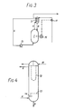
- Figure 3 is a flow diagram of a whole heat removal system from a polymerization reactor
- Figure 4 shows a sectional view of a vertical multitubular type reflux condenser containing therein the washing apparatus indicated by 3 in Figure 3 (corresponding to Figure 1D).
- an unsaturated hydrocarbon monomer having 2 to 8 carbon atoms, an inert hydrocarbon or the liquefied monomer having 3 to 8 carbon atoms as a solvent, an olefin polymerization catalyst, and, usually, hydrogen as a molecular weight regulator are present.
- Suitable unsaturated hydrocarbon monomers are ethylene, propylene, n-butene-1, n-pentene-1, n-hexene-1, 4-methyl pentene-1 and n-octene-1, used alone or as a mixture.
- this monomer may be also used as the solvent.
- the olefin polymerization catalyst may be a catalyst comprising a transition metal compound such as a halogenated titanium compound (e.g., titanium tetrachloride, titanium tetrabromide, titanium trichloride or titanium tribromide), a halogenated vanadium compound (e.g., vanadyl chloride or vanadium tetrachloride) or chromium oxide, and an organometallic compound of Group Ia, IIa or IIIa of the Periodic Table such as an organoaluminum compound (e.g., diethylaluminum chloride or triethyl- aluminum) or an organomagnesium compound (e.g., diethyl magnesium).
- a transition metal compound such as a halogenated titanium compound (e.g., titanium tetrachloride, titanium tetrabromide, titanium trichloride or titanium tribromide), a halogenated vanadium compound (e.
- the gas phase portion in the polymerization reactor contains the monomer and hydrogen in addition to the gaseous solvent.
- a gas mixture is withdrawn from the gas phase portion and introduced as a gas to be condensed through a piping 4 into a washing apparatus-containing reflux condenser 3. At this time, active catalyst particles are entrained in the gas mixture.
- the gas mixture comes in contact with the surface of the heat transfer tube 12 where it is condensed in an amount corresponding to the quantity of heat to be removed in the polymerization reactor.
- the condensed liquid falls on the washing apparatus 13 where it countercurrently contacts with the gas mixture from the polymerization reaction as described above, and it then returns through piping 8 to the polymerization reactor 1 while containing therein the active catalyst particles and polymer particles.
- An uncondensed gas mixture containing the monomer and hydrogen that do not condense on the surface of the heat transfer tube 12 is withdrawn through piping 6 and circulated by a compressor 15 into the liquid phase portion of the polymerization reactor 1.
- the heat quantity to be removed is controlled by regulating the condensation amount in the reflux condenser.
- the amount of the liquid being condensed can be controlled by the amount of cooling water which is supplied through piping 10 into the interior of the heat transfer tube 12 of the condenser.
- the amount of the cooling water is regulated with a control valve 11.
- the heat quantity being removed nearly corresponds to the polymerization heat generated by the polymerization in the polymerization reactor 1.
- the heat removal is carried out by controlling the flow amount of the cooling water so that the temperature of the polymerization reactor 1 is maintained at a constant level.
- Polymerization was carried out according to the flow diagram shown in Figure 3.
- the removal of polymerization heat was carried out using an apparatus shown in Figure 4.
- the operation was continued for 8 months under the above conditions. Under these conditions, a slurry of polymer produced was discharged from the reactor at an average rate of 2,350 kg/hr.
- the slurry comprised a solid polymer (produced at an average rate of 1,250 kg/hr), and liquid propylene containing atactic polymer and dissolved catalyst (1,100 kg/hr on average).
- the quantity of heat removal in the reflux condenser was 400,000 Kcal/hr.
Abstract
Description
- This invention relates to an improved method and apparatus for the removal of heat from a polymerization reactor having a reflux condenser which is used for the catalytic polymerization of olefins in a low boiling point hydrocarbon solvent.
- Recently, with an increase in the amount of polyolefins being produced, there has been a tendency for polymerization reactors of large volume to be employed or for the amount of polyolefins being produced per polymerization reactor to be increased. For heat removal from the polymerization reactor, therefore, various methods as well as the usual heat removal method using a jacket have been developed, including a method in which an internal cooler (e.g., a plate cooler or a coil cooler) is mounted in the polymerization reactor, and a method in which a reflux condenser is used for the heat removal by circulating a liquid phase portion in the polymerization reactor into an external cooler. Such a method using the reflux condenser is described in British Patent 991,397 and U.S. Patents 3,785,430 and 4,061,848.
- The method using the reflux condenser, however, suffers from the disadvantage that when the reflux condenser is continuously used, active catalyst particles and polymer particles, both of which particles are entrained in a gas to be condensed, are deposited on the heat transger surface of the reflux condenser to form scales, or heavier deposits, which result in a reduction of the heat removal ability. Furthermore, these deposits give rise to various problems, that is to say, when they are locally stripped off, they clog a flow path through which the condensed liquid returns to the polymerization reactor, enter the polymerization reactor to adversely affect the quality of polyolefin products, and clog a conduit through which the liquid phase portion in the polymerization reactor is withdrawn. In order to overcome such problems, it is necessary to wash the heat transfer surface of the reflux condenser at 2 or 3 month intervals.
- In order to wash the heat transfer surface, it is necessary to separate the reflux condenser from the polymerization reactor by stopping the polymerization or by extremely reducing the amount of polyolefins being produced. In either case, this leads to a marked reduction in productivity.
- An object of this invention is to provide a method and apparatus for heat removal from a polymerization reactor with a reflux condenser, which method permits to substantially or completely prevent the formation of polymer scales on the heat transfer surface of the reflux condenser.
- It has now been found that the above object is attained by providing a washing system for washing a gas mixture withdrawn from the polymerization reactor before it reaches the heat transfer surface of the reflux condenser.
- This invention, therefore, relates to a method and apparatus for the heat removal from a polymerization reactor with a reflux condenser, in which an unsaturated hydrocarbon monomer having 2 to 8 carbon atoms is polymerized in an inert hydrocarbon or the liquefied monomer having 3 to 8 carbon atoms as a solvent in the presence of an olefin polymerization catalyst, by introducing a gas mixture withdrawn from the polymerization reactor into the reflux condenser where the gas mixture is condensed and separated into a condensed liquid and an uncondensed gas and returning the condensed liquid to the polymerization reactor (by gravity flow or with a pump) and the uncondensed gas into the liquid phase in the polymerization reactor by the use of a compressor, wherein the gas mixture from the polymerization reactor is brought in countercurrent contact with the condensed liquid and/or the solvent to be supplied to the polymerization reactor before the gas mixture reaches the heat transfer surface of the reflux condenser to remove active catalyst particles and polymer particles (both of which particles are entrained in the gas to be condensed).
- As a reflux condenser used in practicing this invention, usual multitubular heat exchangers of either the vertical type or horizontal type can be used.
- A washing apparatus used in this invention is a usual gas-liquid contactor. Preferred examples are trays such as a sieve tray, a turbogrid tray or a ripple tray, scrubbers such as a pibo disc scrubber or a cyclone scrubber and spray towers.
- The reflux condenser and the washing apparatus may be installed separately or combined together to provide a system in which the washing apparatus is contained in the lower portion of the reflux condenser. These embodiments will be hereinafter explained by reference to the accompanying drawings, wherein:-
- Figures 1A to 1F each illustrates a washing system in which a condensed liquid is used as a washing liquid;
- Figures 2A to 2C each illustrates a combination of a washing system in which a solvent to be supplied to a polymerization reactor is used as a washing liquid and a reflux condenser;
- Figure 3 is a flow diagram of a combination of a polymerization reactor and an apparatus for the heat removal from the polymerization reactor; and
- Figure 4 is a sectional view of a reflux condenser containing therein a washing system.
- In Figures 1 to 4,
numeral 1 indicates a polymerization reactor, 2 a washing apparatus, 3 a reflux condenser, 4 piping through which the gas mixture is introduced into the washing apparatus, 5 piping through which the gas mixture withdrawn from the washing apparatus is introduced into the reflux condenser, 6 piping through which the uncondensed gas mixture flows, 7 piping through which the condensed liquid is withdrawn from the reflux condenser, 8 piping through which the liquid is withdrawn from the washing apparatus, 9 piping through which the washing liquid is introduced into the washing apparatus, 10 piping through which the cooling water is supplied, 11 a control valve for cooling water, 12 a heat transfer tube of the condenser, 13 a washing apparatus (tray), 14 a washing apparatus (down comer), 15 a compressor for circulating the uncondensed gas mixture and 16 a temperature regulator. - Figures 1A to 1F each illustrates an embodiment in which the condensed liquid is used as the washing liquid; that is, Figure 1A shows an embodiment in which a vertical type reflux condenser is combined with an independent washing apparatus; Figure 1B an embodiment in which a horizontal type reflux condenser is combined with an independent washing apparatus; Figure 1C an embodiment in which a horizontal type reflux condenser contains therein a washing apparatus; Figure 1D an embodiment in which a vertical type reflux condenser contains a washing apparatus; Figure 1E an embodiment in which a vertical type reflux condenser is combined with a washing apparatus directly mounted on a polymerization reactor; and Figure 1F an embodiment in which a vertical type condenser containing therein a washing apparatus is directly mounted on a polymerization reactor.
- Figures 2A to 2C each illustrates an embodiment in which the solvent to be supplied to the polymerization reactor is used as the washing liquid; that is, Figure 2A shows an embodiment in which a vertical type reflux condenser is combined with an independent washing apparatus; Figure 2B an embodiment in which a horizontal type reflux condenser is combined with an independent washing apparatus; and Figure 2C an embodiment in which a vertical type reflux condenser is combined with a washing apparatus directly mounted on a polymerization reactor.
- This invention will be hereinafter described in greater detail by reference to Figures 3 and 4.
- Figure 3 is a flow diagram of a whole heat removal system from a polymerization reactor, and Figure 4 shows a sectional view of a vertical multitubular type reflux condenser containing therein the washing apparatus indicated by 3 in Figure 3 (corresponding to Figure 1D).
- In the inside of a
polymerization reactor 1, an unsaturated hydrocarbon monomer having 2 to 8 carbon atoms, an inert hydrocarbon or the liquefied monomer having 3 to 8 carbon atoms as a solvent, an olefin polymerization catalyst, and, usually, hydrogen as a molecular weight regulator are present. Suitable unsaturated hydrocarbon monomers are ethylene, propylene, n-butene-1, n-pentene-1, n-hexene-1, 4-methyl pentene-1 and n-octene-1, used alone or as a mixture. If a separate solvent is used, this may be an inert hydrocarbon having 3 to 8 carbon atoms such as propane, n-butane, isobutane, isobutylene, n-hexane, n-heptane or xylene. Furthermore, when the unsaturated hydrocarbon monomer other than ethylene to be polymerized is liquid in the polymerization reactor, this monomer can be also used as the solvent. - The olefin polymerization catalyst may be a catalyst comprising a transition metal compound such as a halogenated titanium compound (e.g., titanium tetrachloride, titanium tetrabromide, titanium trichloride or titanium tribromide), a halogenated vanadium compound (e.g., vanadyl chloride or vanadium tetrachloride) or chromium oxide, and an organometallic compound of Group Ia, IIa or IIIa of the Periodic Table such as an organoaluminum compound (e.g., diethylaluminum chloride or triethyl- aluminum) or an organomagnesium compound (e.g., diethyl magnesium).
- It is not always necessary for the hydrogen, used as a molecular weight regulator, to be present. As the polymerization proceeds, polymerization heat is generated to thereby cause evaporation of the solvent and/or the monomer. The gas phase portion in the polymerization reactor contains the monomer and hydrogen in addition to the gaseous solvent. A gas mixture is withdrawn from the gas phase portion and introduced as a gas to be condensed through a
piping 4 into a washing apparatus-containingreflux condenser 3. At this time, active catalyst particles are entrained in the gas mixture. - When the gas mixture enters the washing apparatus-containing
reflux condenser 3, it first comes in countercurrent contact with the condensed liquid which has been condensed on the surface of aheat transfer tube 12 of the condenser, on a washing apparatus (tray) 13. The countercurrent contact washes off the active catalyst particles and polymer particles entrained in the gas mixture. - Then, the gas mixture comes in contact with the surface of the
heat transfer tube 12 where it is condensed in an amount corresponding to the quantity of heat to be removed in the polymerization reactor. The condensed liquid falls on thewashing apparatus 13 where it countercurrently contacts with the gas mixture from the polymerization reaction as described above, and it then returns throughpiping 8 to thepolymerization reactor 1 while containing therein the active catalyst particles and polymer particles. - An uncondensed gas mixture containing the monomer and hydrogen that do not condense on the surface of the
heat transfer tube 12 is withdrawn throughpiping 6 and circulated by acompressor 15 into the liquid phase portion of thepolymerization reactor 1. - As is well known to one skilled in the art, the heat quantity to be removed is controlled by regulating the condensation amount in the reflux condenser. The amount of the liquid being condensed can be controlled by the amount of cooling water which is supplied through
piping 10 into the interior of theheat transfer tube 12 of the condenser. The amount of the cooling water is regulated with acontrol valve 11. The heat quantity being removed nearly corresponds to the polymerization heat generated by the polymerization in thepolymerization reactor 1. Thus, the heat removal is carried out by controlling the flow amount of the cooling water so that the temperature of thepolymerization reactor 1 is maintained at a constant level. - Although the above explanation has been given for a vertical type of multitubular reflux condenser containing therein a washing apparatus, this invention is not limited thereto; constructions as illustrated in Figures 1 and 2 can easily be employed in this invention.
- This invention is described in greater detail by reference to the following Example and Comparative Example.
- Polymerization was carried out according to the flow diagram shown in Figure 3. The removal of polymerization heat was carried out using an apparatus shown in Figure 4.
- Polymerization Reactor: 30 m3 polymerization reactor with a stirrer
- Reflux Condenser: vertical type of U-shaped multitubular reflux condenser (heat transfer area: 40 m3)
- Washing Apparatus: one-stage turbogrid tray with a down comer which is contained in the lower portion of the reflux condenser
- Monomer and Solvent: propylene
- Polymerization Catalyst: titanium trichloride and diethylaluminum chloride (feed amount: 156 g/hr and 1,000 g/hr, respectively)
- Molecular Weight Regulator: hydrogen
- Temperature of Polymerization Reactor: 70°C
- Pressure of Polymerization Reactor: 31 kg/cm2 (Gauge)
- The operation was continued for 8 months under the above conditions. Under these conditions, a slurry of polymer produced was discharged from the reactor at an average rate of 2,350 kg/hr. The slurry comprised a solid polymer (produced at an average rate of 1,250 kg/hr), and liquid propylene containing atactic polymer and dissolved catalyst (1,100 kg/hr on average). The quantity of heat removal in the reflux condenser was 400,000 Kcal/hr.
- At the end of the time, the reflux condenser was dismantled and inspected. This inspection revealed that almost no deposition of particles of polymer or catalyst on the surface of the heat transfer tube took place. It was observed that the polymer was deposited in a thickness of 6 mm on the walls of the inlet piping through which the gas mixture was introduced into the polymerization reactor.
- The procedure of the Example was repeated with the exception that the washing apparatus (
tray 13 and down comer 14) was not provided. - The operation was continued for 33 days. At the end of this time, the reflux condenser was dismantled and inspected; polymer containing catalyst particles were deposited onto the whole surface of the heat transfer tube in a thickness of 0.1 mm to 10 mm.
Claims (7)
Applications Claiming Priority (2)
| Application Number | Priority Date | Filing Date | Title |
|---|---|---|---|
| JP14536/80 | 1980-02-07 | ||
| JP1453680A JPS56110701A (en) | 1980-02-07 | 1980-02-07 | Method and apparatus for removal of heat from polymerizer |
Publications (3)
| Publication Number | Publication Date |
|---|---|
| EP0034061A2 true EP0034061A2 (en) | 1981-08-19 |
| EP0034061A3 EP0034061A3 (en) | 1982-06-02 |
| EP0034061B1 EP0034061B1 (en) | 1984-10-31 |
Family
ID=11863866
Family Applications (1)
| Application Number | Title | Priority Date | Filing Date |
|---|---|---|---|
| EP81300515A Expired EP0034061B1 (en) | 1980-02-07 | 1981-02-06 | Method and apparatus for removal of heat from an olefin polymerization reactor |
Country Status (7)
| Country | Link |
|---|---|
| US (1) | US4408024A (en) |
| EP (1) | EP0034061B1 (en) |
| JP (1) | JPS56110701A (en) |
| CA (1) | CA1163780A (en) |
| DE (1) | DE3166884D1 (en) |
| HU (1) | HU183315B (en) |
| SG (1) | SG49184G (en) |
Cited By (5)
| Publication number | Priority date | Publication date | Assignee | Title |
|---|---|---|---|---|
| FR2749015A1 (en) * | 1996-05-24 | 1997-11-28 | Bp Chemicals Snc | Process for producing olefin] polymer with a low polydispersity index |
| WO1997045462A1 (en) * | 1996-05-24 | 1997-12-04 | Bp Chemicals Limited | Process for polymerizing olefins |
| WO2005051540A1 (en) * | 2003-11-25 | 2005-06-09 | Consejo Superior De Investigaciones Científicas | Organic/inorganic acid hybrid catalysts, preparation method thereof and use of same |
| CN105377417A (en) * | 2013-07-03 | 2016-03-02 | 切弗朗菲利浦化学公司 | Cooling between multiple polyolefin polymerization reactors |
| US10501566B2 (en) | 2015-09-28 | 2019-12-10 | Mitsubishi Chemical Corporation | Production method of alpha-olefin low polymer and production apparatus |
Families Citing this family (14)
| Publication number | Priority date | Publication date | Assignee | Title |
|---|---|---|---|---|
| US4543399A (en) * | 1982-03-24 | 1985-09-24 | Union Carbide Corporation | Fluidized bed reaction systems |
| US4588790A (en) * | 1982-03-24 | 1986-05-13 | Union Carbide Corporation | Method for fluidized bed polymerization |
| US4555384A (en) * | 1982-09-24 | 1985-11-26 | Cosden Technology, Inc. | Apparatus for producing styrenic/alkenylnitrile copolymers |
| US4551309A (en) * | 1982-09-24 | 1985-11-05 | Cosden Technology, Inc. | Apparatus for producing styrenic/alkenylnitrile copolymers |
| US4548788A (en) * | 1982-09-24 | 1985-10-22 | Cosden Technology, Inc. | Apparatus for producing styrenic/alkenylnitrile copolymers |
| JPS6053513A (en) * | 1983-09-01 | 1985-03-27 | Kuraray Co Ltd | Process for continuous production of ethylene-vinyl acetate copolymer |
| US4742131A (en) * | 1985-12-27 | 1988-05-03 | Mitsui Toatsu Chemicals, Incorporated | Method of controlling polymerization temperature |
| JPH0717705B2 (en) * | 1986-05-10 | 1995-03-01 | 三井東圧化学株式会社 | Method for producing polymer |
| US5393498A (en) * | 1989-02-16 | 1995-02-28 | Lieberam; Kai | Condenser cooling and temperature control system |
| US5527511A (en) * | 1991-02-11 | 1996-06-18 | Fina Technology, Inc. | Apparatus and processes for reducing undesirable volatiles in recycle streams of monovinyl aromatic polymerization systems |
| US5200476A (en) * | 1991-02-08 | 1993-04-06 | Fina Technology, Inc. | Reduction of undesirable volatiles in recycle streams using partial condensation in the reactor vaporization line |
| US5531967A (en) * | 1991-02-11 | 1996-07-02 | Fina Technology, Inc. | Apparatus for reducing polymerization inhibitor in recycle streams |
| DE69411874D1 (en) * | 1993-12-28 | 1998-08-27 | Shinetsu Chemical Co | Polymerization device for the prevention of polymer crust deposition and method for polymer production with this. |
| US6322755B1 (en) † | 1996-08-08 | 2001-11-27 | Shell Oil Company | Reactor for carrying out an exothermic reaction |
Citations (3)
| Publication number | Priority date | Publication date | Assignee | Title |
|---|---|---|---|---|
| GB1053572A (en) * | 1963-05-14 | |||
| GB991397A (en) * | 1963-03-28 | 1965-05-05 | Grace W R & Co | Improvements relating to the production of polyolefines |
| FR2322875A1 (en) * | 1973-01-03 | 1977-04-01 | Basf Ag | METHOD OF EVACUATION OF THE REACTION HEAT DURING THE COPOLYMERIZATION OF ETHYLENE IN AQUEOUS DISPERSION |
Family Cites Families (10)
| Publication number | Priority date | Publication date | Assignee | Title |
|---|---|---|---|---|
| US3349070A (en) * | 1963-04-22 | 1967-10-24 | Shell Oil Co | Bulk polymerization process |
| GB1058359A (en) * | 1965-12-22 | 1967-02-08 | Leuna Werke Veb | Process for the removal of contaminants from circulating gases in the high pressure polymerisation of ethylene |
| BE754808A (en) * | 1969-08-14 | 1971-02-15 | Exxon Research Engineering Co | RECOVERY OF MONOMERS IN A POLYMERIZATION PROCESS |
| US3635931A (en) * | 1969-12-22 | 1972-01-18 | Phillips Petroleum Co | Polyisoprene from amylenes via n-amylene isomerization oxidative dehydrogenation extractive distillation and polymerization of low-concentration isoprene |
| DE2038363B2 (en) * | 1970-08-01 | 1974-10-03 | Chemische Werke Huels Ag, 4370 Marl | Method and device for cooling polymerization batches |
| JPS5030105A (en) * | 1973-07-18 | 1975-03-26 | ||
| DE2458024B2 (en) * | 1974-12-07 | 1979-10-04 | Hoechst Ag, 6000 Frankfurt | Process for the aqueous suspension polymerization of vinyl chloride |
| DE2504659B2 (en) * | 1975-02-05 | 1980-01-17 | Chemische Werke Huels Ag, 4370 Marl | Process for the controlled dissipation of the heat of reaction in polymerization reactions in dispersion or solution |
| JPS5230539A (en) * | 1975-09-02 | 1977-03-08 | Koji Ihara | Pachinko (pinball game) island using square iron pipe as pole |
| US4058652A (en) * | 1976-02-10 | 1977-11-15 | Exxon Research & Engineering Co. | Autorefrigeration process and apparatus |
-
1980
- 1980-02-07 JP JP1453680A patent/JPS56110701A/en active Granted
-
1981
- 1981-02-04 CA CA000370125A patent/CA1163780A/en not_active Expired
- 1981-02-06 EP EP81300515A patent/EP0034061B1/en not_active Expired
- 1981-02-06 HU HU81295A patent/HU183315B/en not_active IP Right Cessation
- 1981-02-06 DE DE8181300515T patent/DE3166884D1/en not_active Expired
- 1981-02-09 US US06/232,486 patent/US4408024A/en not_active Expired - Lifetime
-
1984
- 1984-07-10 SG SG49184A patent/SG49184G/en unknown
Patent Citations (3)
| Publication number | Priority date | Publication date | Assignee | Title |
|---|---|---|---|---|
| GB991397A (en) * | 1963-03-28 | 1965-05-05 | Grace W R & Co | Improvements relating to the production of polyolefines |
| GB1053572A (en) * | 1963-05-14 | |||
| FR2322875A1 (en) * | 1973-01-03 | 1977-04-01 | Basf Ag | METHOD OF EVACUATION OF THE REACTION HEAT DURING THE COPOLYMERIZATION OF ETHYLENE IN AQUEOUS DISPERSION |
Cited By (6)
| Publication number | Priority date | Publication date | Assignee | Title |
|---|---|---|---|---|
| FR2749015A1 (en) * | 1996-05-24 | 1997-11-28 | Bp Chemicals Snc | Process for producing olefin] polymer with a low polydispersity index |
| WO1997045462A1 (en) * | 1996-05-24 | 1997-12-04 | Bp Chemicals Limited | Process for polymerizing olefins |
| US6187881B1 (en) | 1996-05-24 | 2001-02-13 | Bp Chemicals Limited | Process for polymerizing olefins |
| WO2005051540A1 (en) * | 2003-11-25 | 2005-06-09 | Consejo Superior De Investigaciones Científicas | Organic/inorganic acid hybrid catalysts, preparation method thereof and use of same |
| CN105377417A (en) * | 2013-07-03 | 2016-03-02 | 切弗朗菲利浦化学公司 | Cooling between multiple polyolefin polymerization reactors |
| US10501566B2 (en) | 2015-09-28 | 2019-12-10 | Mitsubishi Chemical Corporation | Production method of alpha-olefin low polymer and production apparatus |
Also Published As
| Publication number | Publication date |
|---|---|
| CA1163780A (en) | 1984-03-20 |
| EP0034061A3 (en) | 1982-06-02 |
| DE3166884D1 (en) | 1984-12-06 |
| JPS647084B2 (en) | 1989-02-07 |
| HU183315B (en) | 1984-04-28 |
| US4408024A (en) | 1983-10-04 |
| EP0034061B1 (en) | 1984-10-31 |
| JPS56110701A (en) | 1981-09-02 |
| SG49184G (en) | 1985-03-29 |
Similar Documents
| Publication | Publication Date | Title |
|---|---|---|
| EP0034061B1 (en) | Method and apparatus for removal of heat from an olefin polymerization reactor | |
| CN101910212B (en) | Process for monomer recovery from a polymerization process | |
| US4187278A (en) | Polymerization process | |
| CN101035817B (en) | Polymerisation process | |
| JP5474780B2 (en) | Method for separating hydrocarbon-containing feed streams | |
| US6469110B1 (en) | Process for preparing polypropylene alloys | |
| RU2051923C1 (en) | Method for production of polyolefins and device for its realization | |
| RU2198184C2 (en) | Polymerization process | |
| CN101346174A (en) | Gas-phase process and apparatus for the polymerization of olefins | |
| EA001029B1 (en) | A PROCESS AND APPARATUS FOR POLYMERIZATION OF OLEFIN MONOMERS (57) 1. A process for polymerization of olefin monomer and optionally other monomer in the presence of olefin polymerizing catalyst, diluent and optional co-catalyst and donors, said process comprising the steps: | |
| EA011774B1 (en) | Slurry phase polymerisation process and loop reactor therefor | |
| EP1613668B1 (en) | Gas-phase olefin polymerization process | |
| US4337069A (en) | Gas phase olefin polymerization recycle gas scrubbing tower | |
| US3193360A (en) | Apparatus for propylene polymerization | |
| US4222986A (en) | Autorefrigeration polymerization apparatus | |
| KR20000068966A (en) | Process for making propylene homo or copolymers | |
| US3776979A (en) | Olefin block copolymer fluidized-bed polymerization process | |
| US4058652A (en) | Autorefrigeration process and apparatus | |
| GB2069369A (en) | Method and apparatus for removal of heat from an olefin polymerization reactor | |
| US4214063A (en) | Autorefrigerated polymerization process | |
| EP0038387B1 (en) | Polymerization process | |
| US4420609A (en) | Catalyst deactivation in propylene polymers using ammonium salts | |
| JP4460187B2 (en) | Olefin polymerization method and polymerization apparatus | |
| SU786907A3 (en) | Method of producing polyolefins | |
| JPS62263205A (en) | Production of polyolefin |
Legal Events
| Date | Code | Title | Description |
|---|---|---|---|
| PUAI | Public reference made under article 153(3) epc to a published international application that has entered the european phase |
Free format text: ORIGINAL CODE: 0009012 |
|
| AK | Designated contracting states |
Designated state(s): BE DE FR IT NL |
|
| PUAL | Search report despatched |
Free format text: ORIGINAL CODE: 0009013 |
|
| AK | Designated contracting states |
Designated state(s): BE DE FR IT NL |
|
| 17P | Request for examination filed |
Effective date: 19821104 |
|
| ITF | It: translation for a ep patent filed |
Owner name: SOCIETA' ITALIANA BREVETTI S.P.A. |
|
| GRAA | (expected) grant |
Free format text: ORIGINAL CODE: 0009210 |
|
| AK | Designated contracting states |
Designated state(s): BE DE FR IT NL |
|
| REF | Corresponds to: |
Ref document number: 3166884 Country of ref document: DE Date of ref document: 19841206 |
|
| ET | Fr: translation filed | ||
| PLBE | No opposition filed within time limit |
Free format text: ORIGINAL CODE: 0009261 |
|
| STAA | Information on the status of an ep patent application or granted ep patent |
Free format text: STATUS: NO OPPOSITION FILED WITHIN TIME LIMIT |
|
| 26N | No opposition filed | ||
| ITTA | It: last paid annual fee | ||
| PGFP | Annual fee paid to national office [announced via postgrant information from national office to epo] |
Ref country code: DE Payment date: 19970214 Year of fee payment: 17 |
|
| PGFP | Annual fee paid to national office [announced via postgrant information from national office to epo] |
Ref country code: NL Payment date: 19970227 Year of fee payment: 17 |
|
| PGFP | Annual fee paid to national office [announced via postgrant information from national office to epo] |
Ref country code: BE Payment date: 19970410 Year of fee payment: 17 |
|
| PG25 | Lapsed in a contracting state [announced via postgrant information from national office to epo] |
Ref country code: BE Free format text: LAPSE BECAUSE OF NON-PAYMENT OF DUE FEES Effective date: 19980228 |
|
| BERE | Be: lapsed |
Owner name: SUMITOMO CHEMICAL CY LTD Effective date: 19980228 |
|
| PG25 | Lapsed in a contracting state [announced via postgrant information from national office to epo] |
Ref country code: NL Free format text: LAPSE BECAUSE OF NON-PAYMENT OF DUE FEES Effective date: 19980901 |
|
| NLV4 | Nl: lapsed or anulled due to non-payment of the annual fee |
Effective date: 19980901 |
|
| PG25 | Lapsed in a contracting state [announced via postgrant information from national office to epo] |
Ref country code: DE Free format text: LAPSE BECAUSE OF NON-PAYMENT OF DUE FEES Effective date: 19981103 |
|
| PGFP | Annual fee paid to national office [announced via postgrant information from national office to epo] |
Ref country code: FR Payment date: 19990209 Year of fee payment: 19 |
|
| PG25 | Lapsed in a contracting state [announced via postgrant information from national office to epo] |
Ref country code: FR Free format text: LAPSE BECAUSE OF NON-PAYMENT OF DUE FEES Effective date: 20001031 |
|
| REG | Reference to a national code |
Ref country code: FR Ref legal event code: ST |