EP0033436A1 - Dual-channel data processing system for ensuring the safety of railways - Google Patents
Dual-channel data processing system for ensuring the safety of railways Download PDFInfo
- Publication number
- EP0033436A1 EP0033436A1 EP81100056A EP81100056A EP0033436A1 EP 0033436 A1 EP0033436 A1 EP 0033436A1 EP 81100056 A EP81100056 A EP 81100056A EP 81100056 A EP81100056 A EP 81100056A EP 0033436 A1 EP0033436 A1 EP 0033436A1
- Authority
- EP
- European Patent Office
- Prior art keywords
- output
- data processing
- microcomputers
- amplifier
- signals
- Prior art date
- Legal status (The legal status is an assumption and is not a legal conclusion. Google has not performed a legal analysis and makes no representation as to the accuracy of the status listed.)
- Granted
Links
Images
Classifications
-
- G—PHYSICS
- G06—COMPUTING; CALCULATING OR COUNTING
- G06F—ELECTRIC DIGITAL DATA PROCESSING
- G06F11/00—Error detection; Error correction; Monitoring
- G06F11/07—Responding to the occurrence of a fault, e.g. fault tolerance
- G06F11/16—Error detection or correction of the data by redundancy in hardware
- G06F11/1629—Error detection by comparing the output of redundant processing systems
- G06F11/1633—Error detection by comparing the output of redundant processing systems using mutual exchange of the output between the redundant processing components
-
- B—PERFORMING OPERATIONS; TRANSPORTING
- B61—RAILWAYS
- B61L—GUIDING RAILWAY TRAFFIC; ENSURING THE SAFETY OF RAILWAY TRAFFIC
- B61L7/00—Remote control of local operating means for points, signals, or trackmounted scotch-blocks
- B61L7/06—Remote control of local operating means for points, signals, or trackmounted scotch-blocks using electrical transmission
- B61L7/08—Circuitry
-
- G—PHYSICS
- G06—COMPUTING; CALCULATING OR COUNTING
- G06F—ELECTRIC DIGITAL DATA PROCESSING
- G06F11/00—Error detection; Error correction; Monitoring
- G06F11/07—Responding to the occurrence of a fault, e.g. fault tolerance
- G06F11/0796—Safety measures, i.e. ensuring safe condition in the event of error, e.g. for controlling element
Definitions
- the invention relates to a two-channel data processing arrangement for railway safety purposes with two microcomputers processing the same data, to each of which a comparator is assigned for information to be compared from both microcomputers, which output a switching indicator when information is matched via an output.
- the invention is therefore based on the object of improving a two-channel data processing arrangement of the type mentioned at the outset for use in the field of railway safety engineering in such a way that, using non-secure comparators and avoiding special components, it is ensured that if a signal discrepancy is found between the two data processing systems With Certainly no signals endangering the process are output.
- an AND gate is connected to the output of each of the two comparators, from each of which a second input receives an informationless pulse, that each of the AND gates is followed by a separate pulse amplifier, one of which is the one energy required for its operation from a power supply source and the other from the transformer-coupled and rectified output signals of the first-mentioned pulse amplifier, and that between the outputs of one of the two microcomputers and the devices receiving the signals, active output circuits with transformer-based signal extraction are provided, the power supply of which is transformer-based the output circuit of the second pulse amplifier takes place.
- each of the two AND gates can be connected to the clock current supply of the associated microcomputer with regard to the power supply with an informationless pulse.
- the particular advantage of the two-channel data processing arrangement according to the invention lies in the particularly simple connection of the two channels via the power supply of pulse amplifiers, so that even due to component failures in these modules, a proper state cannot be simulated in an undesirable manner.
- An advantageous development of the invention provides that the output of one and the other AND gate each have an input of the associated Microcomputer is connected. Such a feedback of the pulses present at the outputs of the two AND gates to the assigned processing unit when the entire switching mechanism is in the correct state makes it possible to carry out a channel-specific check from time to time.
- the respective test duration must be shorter than the shortest reaction time of actuators of the railway system controlled by the data processing system.
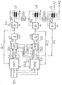
- the block diagram shows in the left part two microcomputers MR1 and MR2 of a two-channel data processing arrangement, which receives all the information which is important for controlling a railway safety system via input lines EN, which are practically representative of a large number of input lines. Also representative of a large number of lines, a data output line DG is connected to the microcomputer MR2, the information of which is available at two terminals K1 and K2 serving as data outputs for an actuator of the railway safety system.
- Different outputs of the microcomputer MR1 are designated 1L1, 1L2 to 1Ln and in the microcomputer MR2 2L1, 2L2 to 2Ln.
- These outputs can carry a wide variety of signals, such as data and / or control information or addresses. All of this information is suitable to be compared in pairs, so that a discrepancy in the functioning of the two microcomputers MR1 and MR2 can be determined as early as possible.
- the two microcomputers MR1 and MR2 are two comparators VR1 and VR2 assigned. Both are connected to the outputs 1L1 to 1Ln and 2L1 to 2Ln of the microcomputers MR1 and MR2.
- an AND gate UD1 or UD2 is connected to the comparator VR1 or VR2, which is connected via a second input E1 or E2 and a control line IG1 or IG2 to the microcomputer MR1 or MR2 present in the relevant processing channel.
- the second pulse amplifier IR2 is not fed from this voltage source; rather, the energy is supplied from the output circuit of the properly working pulse amplifier IR1 to the Purpose must of course be controlled with square wave signals.
- a transformer U1 is provided in the output circuit of the pulse amplifier IR1 with a primary winding U11 and a secondary winding U12.
- a rectifier circuit GG1 is connected to the latter, which in turn feeds the pulse amplifier IR2 and the primary winding U21 of a transformer U2 located in the output circuit of the latter amplifier IR2.
- the secondary winding U22 of this transformer finally feeds a pulse amplifier IR3 connected to the data output line DG via a further rectifier circuit GG2 and the primary winding U31 of a further transformer U3, to whose secondary winding U32 the terminals K1 and K2 forming the data output are connected.
- a pulse amplifier IR3 connected to the data output line DG via a further rectifier circuit GG2 and the primary winding U31 of a further transformer U3, to whose secondary winding U32 the terminals K1 and K2 forming the data output are connected.
- a pulse amplifiers should also be used, which are preferably supplied with energy via the rectifier circuit GG2.
- a line RL1 or RL2 which is connected to the associated microcomputer MR1 or MR2, is connected both to the output of the AND gate UD1 and to the AND gate UD2.
- microcomputers MR1 and MR2 receive unequal signals via the lines RL1 and RL2 outside the test intervals, they can be in a defined state, e.g. Processing standstill, the blocking of the informationless pulses over the lines JG1 or
Abstract
Bei einer nach Sicherheitsprinzipien aufgebauten Datenverarbeitungsanlage in der Form eines 2v2-Systems ist für jeden Verarbeitungskanal ein Mikrocomputer (MR1, MR2) vorgesehen. Beide verarbeiten dieselben Informationen. Die für den Prozeß auszugebenden Steuersignale und Befehle werden durch beide Mikrocomputer (MR1, MR2) ermittelt und paarweise zwei Vergleichern (VR1,VR2) zugeführt, die jeweils ein UND-Glied (UD1, UD2) steuern, welches zusätzlich Taktimpulse aus dem einen bzw. anderen Mikrocomputer (MRI, MR2) erhält. Jedes der UND-Glieder (UD1,UD2) steuert einen Verstärker (IR1,IR2). Die Stromversorgung des einen Verstärkers (IR1) erfolgt aus einer Batterie. Der andere Verstärker (IR2) erhält zur Stromversorgung transformatorisch ausgekoppelte Signale des erstgenannten Verstärkers (IR1). Die für den Prozeß erforderlichen Steuersignale und Befehle kommen schließlich von mindestens einem weiteren Verstärker (IR3), dessen Stromversorgung durch transformatorisch ausgekoppelte Signale des zweiten Verstärkers (IR2) erfolgt. Deise Datenverarbeitungsanlage erfordert in vorteilhafter Weise keine sicheren Vergleicher. Bei einer Signaldiskrepanz zwischen den beiden Mikrocomputern (MR1,MR2) werden an den Prozeß keine diesen etwa gefährdende Signale ausgegeben.In a data processing system constructed in accordance with security principles in the form of a 2v2 system, a microcomputer (MR1, MR2) is provided for each processing channel. Both process the same information. The control signals and commands to be output for the process are determined by both microcomputers (MR1, MR2) and are supplied in pairs to two comparators (VR1, VR2), each of which controls an AND gate (UD1, UD2), which additionally generates clock pulses from one or other microcomputers (MRI, MR2). Each of the AND gates (UD1, UD2) controls an amplifier (IR1, IR2). One amplifier (IR1) is powered by a battery. The other amplifier (IR2) receives transformer-coupled signals from the former amplifier (IR1) for power supply. The control signals and commands required for the process finally come from at least one further amplifier (IR3), the power supply of which is provided by signals from the second amplifier (IR2) which are coupled out by transformers. The data processing system advantageously does not require reliable comparators. If there is a signal discrepancy between the two microcomputers (MR1, MR2), no signals which might endanger the process are output to the process.
Description
Die Erfindung bezieht sich auf eine zweikanalige Datenverarbeitungsanordnung für Eisenbahnsicherungszwecke mit zwei dieselben Daten verarbeitenden Mikrocomputern, denen für zu vergleichende Informationen beider Microcomputer je ein Vergleicher zugeordnet ist, die bei übereinstimmenden Informationen über jeweils einen Ausgang ein Schaltkennzeichen ausgeben.The invention relates to a two-channel data processing arrangement for railway safety purposes with two microcomputers processing the same data, to each of which a comparator is assigned for information to be compared from both microcomputers, which output a switching indicator when information is matched via an output.
Die im Eisenbahnsicherungswesen eingesetzten Schaltwerke müssen vielfach Sicherheitsverantwortung übernehmen. Dies betrifft Stellwerksanlagen, Streckengeräte für die Zugbeeinflussung oder auch Einrichtungen auf den Schienenfahrzeugen selbst. Aus diesem Grunde müssen Datenverarbeitungsanlagen, die in zunehmendem Maße auch durch Mikrocomputer realisiert werden, nach anerkannten Sicherheitsprinzipien arbeiten, bei denen bei evtl. auftretenden technischen Fehlern der Prozeß, also die zu steuernde Eisenbahn, in einen für den Menschen ungefährlichen Zustand überführt wird. Dies kann beispsielsweise dadurch geschehen, daß unter Anwendung der seit vielen Jahren auf dem Eisenbahnsicherungsgebiet anerkannten Sicherheitsphilosophie allen als gefährlich anerkannten Signalen hoher Signalpegel oder eine Wechselspannung zugeordnet wird, die bei einer Störung der betreffenden Datenverarbeitungsanlage auf allen Ausgabekanälen abgeschaltet wird. Hierzu sind jedoch Einrichtungen erforderlich, die eine fehlerhafte Datenverarbeitung so rechtzeitig erkennen, daß die durch eine fehlerhafte Datenverarbeitungsanlage ermittelten Steuerbefehle nicht zum steuernden Prozeß gelangen.The rear derailleurs used in railway safety systems often have to assume safety responsibility. This applies to interlocking systems, line devices for train control or even facilities on the rail vehicles themselves. For this reason, data processing systems, which are increasingly implemented by microcomputers, must work according to recognized safety principles, in which the process, i.e. the railway to be controlled is brought into a state which is harmless to humans. This can be done, for example, by using the safety philosophy that has been recognized in the railway security field for many years to assign all signals recognized as dangerous to high signal levels or an AC voltage which is switched off on all output channels in the event of a fault in the data processing system concerned. For this purpose, however, devices are required which recognize faulty data processing in time so that the faulty data processing system determined control commands do not get to the controlling process.
Bei einer bekannten Datenverarbeitungsanlage der eingangs genannten Art (DE-OS 2 319 753) wird zur Erhöhung der Verfügbarkeit der Gesamtanlage nach dem Auftreten eines Fehlers in einer ersten zweier Datenverarbeitungsanlagen auf die andere Datenverarbeitungsanlage umgeschaltet, die im Parallelbetrieb ständig mitarbeitet und von der angenommen wird, daß sie nicht zu demselben Zeitpunkt ebenfalls defekt wurde. Bei diesen bekannten 2v2-Systemen kann nur unter Anwendung eines besonderen Aufwandes festgestellt werden, welche von den beiden Datenverarbeitungsanlagen im Störungsfall ein falsches Ergebnis lieferte.In a known data processing system of the type mentioned at the outset (DE-OS 2 319 753), in order to increase the availability of the overall system after a fault occurs in a first two data processing systems, a switch is made to the other data processing system, which is constantly cooperating in parallel operation and which is accepted. that it wasn't broken at the same time. In these known 2v2 systems, it can only be determined with a special effort which of the two data processing systems gave a wrong result in the event of a fault.
Im Hinblick auf die erforderliche Sicherheit kann nun keine Beschränkung dahingehend erfolgen, daß nur bestimmte Anlagenteile eines verdoppelten Datenverarbeitungssystems abgeschaltet werden, weil hierfür kein genügend sicherer Fehlererkennungsmechanismus enthalten ist. Es hätte daher auch keinen Zweck, mit nur einem sicher als intakt erkannten Rechner weiterzuarbeiten, weil dieser aus Mangel eines sicheren Fehlererkennungsmechanismus in Alleinarbeit Gefährdungen für den Menschen und das Material verursachen kann.With regard to the required security, there can be no restriction to the effect that only certain system parts of a doubled data processing system are switched off because there is no sufficiently reliable error detection mechanism for this. There would therefore be no point in continuing to work with only one computer that is reliably recognized as intact, because, due to the lack of a secure error detection mechanism, working alone can endanger people and the material.
Der Erfindung liegt daher die Aufgabe zugrunde, eine zweikanalige Datenverarbeitungsanordnung der eingangs genannten Art für die Verwendung auf dem Gebiete des Eisenbahnsicherungswesens dahingehend zu verbessern, daß unter Verwendung von nicht sicheren Vergleichern und Vermeidung spezieller Bausteine gewährleistet wird, daß bei einer festgestellten Signaldiskrepanz zwischen den beiden Datenverarbeitungsanlagen mit Sicherheit keine den Prozeß gefährdenden Signale ausgegeben werden.The invention is therefore based on the object of improving a two-channel data processing arrangement of the type mentioned at the outset for use in the field of railway safety engineering in such a way that, using non-secure comparators and avoiding special components, it is ensured that if a signal discrepancy is found between the two data processing systems With Certainly no signals endangering the process are output.
Erfindungsgemäß wird die Aufgabe dadurch gelöst, daß an den Ausgang jedes der beiden Vergleicher ein UND-Glied angeschlossen ist, von dem jeweils ein zweiter Eingang einen informationslosen Puls erhält, daß jedem der UND-Glieder ein gesonderter Impulsverstärker nachgeschaltet ist, von denen der eine die für seinen Betrieb erforderliche Energie aus einer Stromversorgungsquelle und der andere aus den transformatorisch ausgekoppelten und gleichgerichteten Ausgangssignalen des erstgenannten Impulsverstärkers erhält, und daß zwischen den Ausgängen eines der beiden Mikrocomputer und den die Signale aufnehmenden Einrichtungen aktive Ausgabeschaltungen mit transformatorischer Signalauskopplung vorgesehen sind, deren Stromversorgung transformatorisch über den Ausgangskreis des zweiten Impulsverstärkers erfolgt.According to the invention the object is achieved in that an AND gate is connected to the output of each of the two comparators, from each of which a second input receives an informationless pulse, that each of the AND gates is followed by a separate pulse amplifier, one of which is the one energy required for its operation from a power supply source and the other from the transformer-coupled and rectified output signals of the first-mentioned pulse amplifier, and that between the outputs of one of the two microcomputers and the devices receiving the signals, active output circuits with transformer-based signal extraction are provided, the power supply of which is transformer-based the output circuit of the second pulse amplifier takes place.
In vorteilhafter Weise kann jedes der beiden UND-Glieder hinsichtlich der Stromversorgung mit einem informationslosen Puls mit der Taktstromversorgung des zugeordneten Mikrocomputers verbunden sein. Der besondere Vorteil der erfindungsgemäßen zweikanaligen Datenverarbeitungsanordnung liegt in der besonders einfachen Verknüpfung der beiden Kanäle über die Stromversorgung von Impulsverstärkern, so daß auch infolge von Bauteilausfällen in diesen Baugruppen in unerwünschter Weise kein ordnungsgerechter Zustand vorgetäuscht werden kann.Advantageously, each of the two AND gates can be connected to the clock current supply of the associated microcomputer with regard to the power supply with an informationless pulse. The particular advantage of the two-channel data processing arrangement according to the invention lies in the particularly simple connection of the two channels via the power supply of pulse amplifiers, so that even due to component failures in these modules, a proper state cannot be simulated in an undesirable manner.
Eine vorteilhafte Weiterbildung der Erfindung sieht vor, daß der Ausgang des einen und des anderen UND-Gliedes jeweils mit einem Eingang des zugeordneten Mikrocomputers verbunden ist. Durch eine derartige Rückführung der an den Ausgängen der beiden UND-Glieder bei ordnungsgerechtem Zustand des gesamten Schaltwerkes vorhandenen Impulse an die zugeordnete Verarbeitungseinheit ist es mögliche von Zeit zu Zeit eine kanalspezifische Überprüfung vorzunehmen. Die jeweilige Prüfdauer muß dabei kleiner sein als die kleinste Reaktionszeit von Stellgliedern der durch die Datenverarbeitungsanlage gesteuerten Eisenbahnanlage.An advantageous development of the invention provides that the output of one and the other AND gate each have an input of the associated Microcomputer is connected. Such a feedback of the pulses present at the outputs of the two AND gates to the assigned processing unit when the entire switching mechanism is in the correct state makes it possible to carry out a channel-specific check from time to time. The respective test duration must be shorter than the shortest reaction time of actuators of the railway system controlled by the data processing system.
Ein Ausführungsbeispiel der Erfindung ist in der Zeichnung dargestellt und wird nachstehend näher erläutert. Das Blockschaltbild zeigt im linken Teil zwei Mikrocomputer MR1 und MR2 einer zweikanaligen Datenverarbeitungsanordnung, die über Eingangsleitungen EN, die praktisch stellvertretend sind für eine Vielzahl von Eingangsleitungen, alle diejenigen Informationen erhält, die zur Steuerung einer Eisenbahnsicherungsanlage von Wichtigkeit sind. Ebenfalls stellvertretend für eine Vielzahl von Leitungen ist an den Mikrocomputer MR2 eine Datenausgangsleitung DG angeschlossen, deren Informationen an zwei als Datenausgang dienenden Klemmen K1 und K2 für ein Stellglied der Eisenbahnsicherungsanlage zur Verfügung stehen. Verschiedene Ausgänge des Mikrocomputers MR1 sind mit 1L1, 1L2 bis 1Ln und beim Mikrocomputer MR2 mit 2L1, 2L2 bis 2Ln bezeichnet. Diese Ausgänge können die vielfältigsten Signale führen, z.B. Daten und/oder Steuerinformationen oder auch Adressen. Alle diese Informationen sind geeignet, jeweils paarweise verglichen zu werden, damit möglichst frühzeitig eine Diskrepanz in der Arbeitsweise der beiden Mikrocomputer MR1 und MR2 festgestellt werden kann. Zum Zwecke der Fehlererkennung sind den beiden Mikrocomputern MR1 und MR2 zwei Vergleicher VR1 und VR2 zugeordnet. Beide sind mit den Ausgängen 1L1 bis 1Ln und 2L1 bis 2Ln der Mikrocomputer MR1 und MR2 verbunden. Wesentlich ist nun für das vorliegende 2v2-System, daß mit Hilfe der Vergleicher VR1, VR2, die nicht unbedingt aus fehlersicheren Bausteinen aufgebaut sein müssen, Schaltkennzeichen abgeleitet werden, die es im Fehlerfall gestatten, daß mit Sicherheit an den Klemmen K1 und K2 kein Signal für das zu steuernde Stellelement (nicht dargestellt) ausgegeben wird. So ist an den Vergleicher VR1 bzw. VR2 ein UND-Glied UD1 bzw. UD2 angeschlossen, welches über einen zweiten Eingang E1 bzw. E2 und eine Steuerleitung IG1 bzw. IG2 mit dem in dem betreffenden Verarbeitungskanal vorhandenen Mikrocomputer MR1 bzw. MR2 verbunden ist. Über die Steuerleitung IG1 bzw. IG2 gelangen auf das zugeordnete UND-Glied UD1 bzw. UD2 informationslose Impulse aus der Taktstromversorgung des zugeordneten Mikrocomputers MR1 bzw. MR2; es wäre aber auch eine gemeinsame gesonderte Impulsquelle denkbar. Durch diese Schaltungsmaßnahme wird erreicht, daß am Ausgang des UND-Gliedes UD1 bzw. UD2 immer dann rechteckförmige Signale anstehen, wenn der Vergleicher VR1 bzw. VR2 einen ordnungsgerechten Zustand festgestellt hat, also von beiden Mikrocomputern MR1 und MR2 gleichartige Signale vorliegen. Die von den UND-Gliedern UD1 und UD2 dann ausgegebenen Rechtecksignale gelangen jeweils auf einen ersten bzw. zweiten Impulsverstärker IR1, IR2. Der Impulsverstärker IR1 ist hinsichtlich der Energieversorgung an eine vorhandene Spannungsquelle angeschlossen; dies ist durch ein in Klammern gesetztes Pluszeichen angedeutet. Der zweite Impulsverstärker IR2 wird nicht aus dieser Spannungsquelle gespeist; vielmehr erfolgt die Energiezufuhr aus dem Ausgangskreis des ordnungsgerecht arbeitenden Impulsverstärkers IR1, der zu dem Zweck selbstverständlich mit Rechtecksignalen angesteuert werden muß. Zum Zwecke der Energieversorgung ist im Ausgangskreis des Impulsverstärkers IR1 ein Transformator U1 vorgesehen mit einer Primärwicklung U11 und einer Sekundärwicklung U12. An die letztgenannte ist eine Gleichrichterschaltung GG1 angeschlossen, die wiederum den Impulsverstärker IR2 sowie die Primärwicklung U21 eines im Ausgangskreis des letztgenannten Verstärkers IR2 liegenden Transformators U2 speist. Die Sekundärwicklung U22 dieses Transformators speist schließlich über eine weitere Gleichrichterschaltung GG2 einen an die Datenausgangsleitung DG angeschlossenen Impulsverstärker IR3 sowie die Primärwicklung U31 eines weiteren Transformators U3, an dessen Sekundärwicklung U32 die den Datenausgang bildenden Klemmen K1 und K2 angeschlossen sind. Selbstverständlich sind im praktischen Betrieb wesentlich mehr Ausgangsleitungen entsprechend der Datenausgangsleitung DG vorgesehen. In dem Fall ist auch eine Vielzahl von Impulsverstärkern einzusetzen, die vorzugsweise über die Gleichrichterschaltung GG2 mit Energie versorgt werden.An embodiment of the invention is shown in the drawing and is explained in more detail below. The block diagram shows in the left part two microcomputers MR1 and MR2 of a two-channel data processing arrangement, which receives all the information which is important for controlling a railway safety system via input lines EN, which are practically representative of a large number of input lines. Also representative of a large number of lines, a data output line DG is connected to the microcomputer MR2, the information of which is available at two terminals K1 and K2 serving as data outputs for an actuator of the railway safety system. Different outputs of the microcomputer MR1 are designated 1L1, 1L2 to 1Ln and in the microcomputer MR2 2L1, 2L2 to 2Ln. These outputs can carry a wide variety of signals, such as data and / or control information or addresses. All of this information is suitable to be compared in pairs, so that a discrepancy in the functioning of the two microcomputers MR1 and MR2 can be determined as early as possible. For the purpose of error detection, the two microcomputers MR1 and MR2 are two comparators VR1 and VR2 assigned. Both are connected to the outputs 1L1 to 1Ln and 2L1 to 2Ln of the microcomputers MR1 and MR2. It is now essential for the present 2v2 system that with the help of the comparators VR1, VR2, which do not necessarily have to be constructed from fail-safe components, switching indicators are derived which, in the event of a fault, permit that there is definitely no signal at terminals K1 and K2 is output for the control element to be controlled (not shown). Thus, an AND gate UD1 or UD2 is connected to the comparator VR1 or VR2, which is connected via a second input E1 or E2 and a control line IG1 or IG2 to the microcomputer MR1 or MR2 present in the relevant processing channel. Via the control line IG1 or IG2, information-free pulses from the clock current supply of the assigned microcomputer MR1 or MR2 arrive at the assigned AND gate UD1 or UD2; but a common separate pulse source would also be conceivable. This circuit measure ensures that rectangular signals are always present at the output of the AND gate UD1 or UD2 when the comparator VR1 or VR2 has determined a correct state, that is to say signals of the same type are present from both microcomputers MR1 and MR2. The square-wave signals then output by the AND gates UD1 and UD2 each arrive at a first or second pulse amplifier IR1, IR2. The pulse amplifier IR1 is connected to an existing voltage source with regard to the energy supply; this is indicated by a plus sign in brackets. The second pulse amplifier IR2 is not fed from this voltage source; rather, the energy is supplied from the output circuit of the properly working pulse amplifier IR1 to the Purpose must of course be controlled with square wave signals. For the purpose of energy supply, a transformer U1 is provided in the output circuit of the pulse amplifier IR1 with a primary winding U11 and a secondary winding U12. A rectifier circuit GG1 is connected to the latter, which in turn feeds the pulse amplifier IR2 and the primary winding U21 of a transformer U2 located in the output circuit of the latter amplifier IR2. The secondary winding U22 of this transformer finally feeds a pulse amplifier IR3 connected to the data output line DG via a further rectifier circuit GG2 and the primary winding U31 of a further transformer U3, to whose secondary winding U32 the terminals K1 and K2 forming the data output are connected. Of course, in practical operation, significantly more output lines are provided corresponding to the data output line DG. In this case, a large number of pulse amplifiers should also be used, which are preferably supplied with energy via the rectifier circuit GG2.
Charakteristisch ist für die oben beschriebene zweikanalige Datenverarbeitungsanordnung, daß nicht nur dann die Ausgabe von Signalen unterbleibt, wenn einer der Mikrocomputer MR1 bzw. MR2 fehlerhaft arbeitet, sondern auch dann, wenn infolge eines Fehlers beim Vergleicher VR1 bzw. VR2 das diesem nachgeschaltete UND-Glied UD1 bzw. UD2 abgeschaltet wird. Denn auch bei einem Fehler bei den letztgenannten UND-Gliedern oder in einem diesen nachgeschalteten Impulsverstärkern IR1 und IR2 unterbleibt die im Fehlerfall nicht gewünschte Datenausgabe.It is characteristic of the two-channel data processing arrangement described above that not only does the output of signals not occur when one of the microcomputers MR1 or MR2 is malfunctioning, but also when the AND element connected downstream as a result of an error in the comparator VR1 or VR2 UD1 or UD2 is switched off. Because even in the event of an error in the latter AND elements or in a pulse amplifier IR1 and IR2 connected downstream, the data output which is not desired in the event of an error is omitted.
Sowohl an den Ausgang des UND-Gliedes UD1 als auch beim UND-Glied UD2 ist eine Leitung RL1 bzw. RL2 angeschlossen, die mit dem zugehörigen Mikrocomputer MR1 bzw. MR2 verbunden ist. Mit Hilfe einer derartigen Rückführung ist es möglich, von Zeit zu Zeit die Funktionsfähigkeit des Vergleichers VR1 bzw. VR2 und des jeweiligen UND-Gliedes UD1 bzw. UD2 durch absichtlich ungleich ausgegebene Daten kanalspezifisch zu überprüfen, so daß sichergestellt ist, daß der betreffende Vergleicher bei im Fehlerfall anstehenden antivalentem Signalpaar auch wirklich kein Ausgangssignal mehr abgibt, so daß der nachgeschaltete Impulsverstärker IR1 bzw. IR2 abgeschaltet wird. Die Prüfdauer muß bei diesem Test kleiner sein als die kleinste Reaktionszeit des an die Klemmen Klund K2 angeschlossenen Stellgliedes.A line RL1 or RL2, which is connected to the associated microcomputer MR1 or MR2, is connected both to the output of the AND gate UD1 and to the AND gate UD2. With the help of such a feedback, it is possible from time to time to check the operability of the comparator VR1 or VR2 and the respective AND gate UD1 or UD2 by deliberately unequally output data, so that it is ensured that the comparator in question in the event of an error, the pending pair of equivalent signals really no longer emits an output signal, so that the downstream pulse amplifier IR1 or IR2 is switched off. The test duration for this test must be less than the shortest reaction time of the actuator connected to terminals Klund K2.
Aufgrund der erläuterten Prüfung ist es in vorteilhafter Weise möglich, die zweikanalige Datenverarbeitungsanordnung unabhängig vom betrieblichen Geschehen, also unabhängig vom Datenfluß, auf ordnungsgerechtes Arbeiten fortlaufend in regelmäßigen Zeitabständen zu prüfen und somit frühzeitig einen ersten Fehler in einem der Schaltungsteile VR1, VR2, UD1 bzw. UD2 zu entdecken. Dann kann über eine die beiden Mikrocomputer MR1 und MR2 verbindende Datenaustauschleitung DLG ein derartiger Datenaustausch erfolgen, daß es zur Abschaltung des gesamten Systems kommt. Dies ist beispielsweise dadurch möglich, daß die beiden Vergleicher VR1 und VR2 hinsichtlich ihrer Eingangssignale in einen festgelegten Ungleichzustand versetzt werden, der auch dann erhalten bleibt, wenn beide Mikrocomputer MR1 und MR2 abgeschaltet werden.On the basis of the test explained, it is advantageously possible to continuously check the two-channel data processing arrangement for proper work independently of the operational situation, that is to say independently of the data flow, at regular time intervals and thus early to detect a first error in one of the circuit parts VR1, VR2, UD1 or Discover UD2. Data can then be exchanged via a data exchange line DLG connecting the two microcomputers MR1 and MR2 such that the entire system is switched off. This is possible, for example, in that the two comparators VR1 and VR2 are set to a defined inequality in terms of their input signals, which state is maintained even when both microcomputers MR1 and MR2 are switched off.
Empfangen die Mikrocomputer MR1 und MR2 über die Leitungen RL1 bzw. RL2 außerhalb der Prüfintervalle Ungleichsignale, so können sie in einem definierten Zustand, z.B. Verarbeitungsstillstand, übergehen, der das Blockieren der informationslosen Pulse über die Leitungen JG1 bzw.If the microcomputers MR1 and MR2 receive unequal signals via the lines RL1 and RL2 outside the test intervals, they can be in a defined state, e.g. Processing standstill, the blocking of the informationless pulses over the lines JG1 or
JG2 mit einschließt. Solange wenigstens einer der informationslosen Pulse über eine der Leitungen JG1 bzw. JG2 ausbleibt oder wenigstens einer der Vergleicher VR1 bzw. VR2 dauerhaft "ungleich" meldet und das jeweils nachgeschaltete UND-Glied UD1 bzw. UD2 sperrt, bleibt der Eingang des zugehörigen Impulsverstärkers JR1 bzw. JR2 dauerhaft blockiert, wodurch die Gleichrichterschaltung GG1, nicht mehr mit Energie versorgt wird. Mit Sicherheit triff dies besonders für die Gleichrichterschaltung GG2 zu.Includes JG2. As long as at least one of the informationless pulses via one of the lines JG1 or JG2 is absent or at least one of the comparators VR1 or VR2 permanently reports "unequal" and the respective downstream AND gate UD1 or UD2 blocks, the input of the associated pulse amplifier JR1 or JR2 is permanently blocked, as a result of which the rectifier circuit GG1 is no longer supplied with energy. This is certainly the case for the GG2 rectifier circuit.
Claims (3)
Priority Applications (1)
| Application Number | Priority Date | Filing Date | Title |
|---|---|---|---|
| AT81100056T ATE3127T1 (en) | 1980-01-30 | 1981-01-07 | TWO-CHANNEL DATA PROCESSING ARRANGEMENT FOR RAILWAY SAFETY PURPOSES. |
Applications Claiming Priority (2)
| Application Number | Priority Date | Filing Date | Title |
|---|---|---|---|
| DE3003291A DE3003291C2 (en) | 1980-01-30 | 1980-01-30 | Two-channel data processing arrangement for railway safety purposes |
| DE3003291 | 1980-01-30 |
Publications (2)
| Publication Number | Publication Date |
|---|---|
| EP0033436A1 true EP0033436A1 (en) | 1981-08-12 |
| EP0033436B1 EP0033436B1 (en) | 1983-04-20 |
Family
ID=6093273
Family Applications (1)
| Application Number | Title | Priority Date | Filing Date |
|---|---|---|---|
| EP81100056A Expired EP0033436B1 (en) | 1980-01-30 | 1981-01-07 | Dual-channel data processing system for ensuring the safety of railways |
Country Status (12)
| Country | Link |
|---|---|
| US (1) | US4400792A (en) |
| EP (1) | EP0033436B1 (en) |
| JP (1) | JPS56121151A (en) |
| AR (1) | AR227170A1 (en) |
| AT (1) | ATE3127T1 (en) |
| CA (1) | CA1162311A (en) |
| DE (1) | DE3003291C2 (en) |
| DK (1) | DK148560C (en) |
| FI (1) | FI70650C (en) |
| IN (1) | IN152462B (en) |
| YU (1) | YU42999B (en) |
| ZA (1) | ZA81603B (en) |
Cited By (4)
| Publication number | Priority date | Publication date | Assignee | Title |
|---|---|---|---|---|
| EP0156388A2 (en) * | 1984-03-30 | 1985-10-02 | Licentia Patent-Verwaltungs-GmbH | Technically signal-secure data processing arrangement |
| EP0428934A2 (en) * | 1989-11-20 | 1991-05-29 | Siemens Aktiengesellschaft | Method of operating a multi-channel fail-safe computer system and device for implementing the method |
| EP0473834A1 (en) * | 1990-09-07 | 1992-03-11 | Siemens Aktiengesellschaft | Electronic interlocking control system, set up according to the local processor control principle |
| FR2751445A1 (en) * | 1996-07-19 | 1998-01-23 | Mitsubishi Electric Corp | LOCKING DEVICE WITH DUAL COMPUTER SYSTEM |
Families Citing this family (49)
| Publication number | Priority date | Publication date | Assignee | Title |
|---|---|---|---|---|
| DE3137450C2 (en) * | 1981-09-21 | 1984-03-22 | Siemens AG, 1000 Berlin und 8000 München | Safety output circuit for a data processing system |
| EP0112837A1 (en) * | 1982-02-11 | 1984-07-11 | Zf-Herion-Systemtechnik Gmbh | Electronic control with safety mechanisms |
| DE3303791C2 (en) * | 1982-02-11 | 1992-04-16 | ZF-Herion-Systemtechnik GmbH, 7990 Friedrichshafen | Electronic control with safety devices |
| FR2540685A1 (en) * | 1983-02-03 | 1984-08-10 | Jeumont Schneider | INTERFACE FOR CONNECTING A COMPUTER SYSTEM TO AN ACTUATOR DEVICE |
| GB8401806D0 (en) * | 1984-01-24 | 1984-02-29 | Int Computers Ltd | Data storage apparatus |
| JPS6182201A (en) * | 1984-09-29 | 1986-04-25 | Nec Home Electronics Ltd | Fail-safe controlling circuit |
| US4665522A (en) * | 1985-01-28 | 1987-05-12 | The Charles Stark Draper Laboratory, Inc. | Multi-channel redundant processing systems |
| AU568977B2 (en) * | 1985-05-10 | 1988-01-14 | Tandem Computers Inc. | Dual processor error detection system |
| DE3522418A1 (en) * | 1985-06-22 | 1987-01-02 | Standard Elektrik Lorenz Ag | DEVICE FOR REPORTING THE OCCUPANCY CONDITION OF TRACK SECTIONS IN THE AREA OF AN ACTUATOR |
| JPS62130429A (en) * | 1985-12-02 | 1987-06-12 | Nec Home Electronics Ltd | Recognizing device for read data |
| IT1213344B (en) * | 1986-09-17 | 1989-12-20 | Honoywell Information Systems | FAULT TOLERANCE CALCULATOR ARCHITECTURE. |
| DE3700986C2 (en) * | 1987-01-15 | 1995-04-20 | Bosch Gmbh Robert | Device for monitoring a computer system with two processors in a motor vehicle |
| DE3708055A1 (en) * | 1987-03-12 | 1988-09-22 | Siemens Ag | SAFETY SWITCHGEAR WITH MULTIPLE MICROCOMPUERS PROCESSING THE SAME DATA |
| JPH061402B2 (en) * | 1987-03-20 | 1994-01-05 | 住友電気工業株式会社 | Multiple system control circuit |
| SE457391B (en) * | 1987-04-16 | 1988-12-19 | Ericsson Telefon Ab L M | PROGRAM MEMORY MANAGED REAL TIME SYSTEM INCLUDING THREE MAINLY IDENTICAL PROCESSORS |
| US4907228A (en) * | 1987-09-04 | 1990-03-06 | Digital Equipment Corporation | Dual-rail processor with error checking at single rail interfaces |
| US4916704A (en) * | 1987-09-04 | 1990-04-10 | Digital Equipment Corporation | Interface of non-fault tolerant components to fault tolerant system |
| DE3854026D1 (en) * | 1987-09-04 | 1995-07-27 | Digital Equipment Corp | Fault-tolerant computer system with error limitation. |
| EP0306211A3 (en) * | 1987-09-04 | 1990-09-26 | Digital Equipment Corporation | Synchronized twin computer system |
| US5185877A (en) * | 1987-09-04 | 1993-02-09 | Digital Equipment Corporation | Protocol for transfer of DMA data |
| GB8729901D0 (en) * | 1987-12-22 | 1988-02-03 | Lucas Ind Plc | Dual computer cross-checking system |
| US4903191A (en) * | 1987-12-23 | 1990-02-20 | E. I. Du Pont De Nemours And Company | Centrifuge control system having dual processors |
| DE3801123A1 (en) * | 1988-01-16 | 1989-07-27 | Philips Patentverwaltung | MEDIATION SYSTEM |
| JPH07117905B2 (en) * | 1989-02-09 | 1995-12-18 | 日本電気株式会社 | Microprocessor |
| GB2228114B (en) * | 1989-02-13 | 1993-02-10 | Westinghouse Brake & Signal | A system comprising a processor |
| US5068851A (en) * | 1989-08-01 | 1991-11-26 | Digital Equipment Corporation | Apparatus and method for documenting faults in computing modules |
| DE69027491T2 (en) * | 1989-08-01 | 1997-02-06 | Digital Equipment Corp | Software error handling procedures |
| US5163138A (en) * | 1989-08-01 | 1992-11-10 | Digital Equipment Corporation | Protocol for read write transfers via switching logic by transmitting and retransmitting an address |
| US5153881A (en) * | 1989-08-01 | 1992-10-06 | Digital Equipment Corporation | Method of handling errors in software |
| US5251227A (en) * | 1989-08-01 | 1993-10-05 | Digital Equipment Corporation | Targeted resets in a data processor including a trace memory to store transactions |
| US5068780A (en) * | 1989-08-01 | 1991-11-26 | Digital Equipment Corporation | Method and apparatus for controlling initiation of bootstrap loading of an operating system in a computer system having first and second discrete computing zones |
| US5048022A (en) * | 1989-08-01 | 1991-09-10 | Digital Equipment Corporation | Memory device with transfer of ECC signals on time division multiplexed bidirectional lines |
| US5065312A (en) * | 1989-08-01 | 1991-11-12 | Digital Equipment Corporation | Method of converting unique data to system data |
| JPH03293906A (en) * | 1990-04-10 | 1991-12-25 | Mitsubishi Electric Corp | Train-operation control-command transmitter |
| DE4032033A1 (en) * | 1990-10-09 | 1992-04-16 | Siemens Ag | Electric control and monitoring for underground plant - triggering safety-relevant signals for transmission over independent paths and processing by redundant systems |
| EP0575942A3 (en) * | 1992-06-23 | 1995-10-25 | Hitachi Ltd | Display apparatus and method |
| JP3343143B2 (en) * | 1992-12-02 | 2002-11-11 | 日本電気株式会社 | Failure diagnosis method |
| FR2704329B1 (en) * | 1993-04-21 | 1995-07-13 | Csee Transport | Security system with microprocessor, applicable in particular to the field of rail transport. |
| US5485379A (en) * | 1994-07-25 | 1996-01-16 | Kelsey Hayes Company | Method and system for detecting the proper functioning of an ABS control unit utilizing substantially identical programmed microprocessors |
| JP3412349B2 (en) * | 1994-12-28 | 2003-06-03 | 株式会社日立製作所 | Control device |
| US7302587B2 (en) * | 2001-06-08 | 2007-11-27 | Matra Transport International | Secure computer system |
| ITTO20040179A1 (en) † | 2004-03-17 | 2004-06-17 | Sab Wabco Spa | BRAKING CONTROL SYSTEM OF A RAILWAY OR RAILWAY VEHICLE WITH INTEGRATED FUNCTIONS OF ANTI-SKATING AND ANTI-LOCKING OF ROUTES |
| ITTO20040325A1 (en) * | 2004-05-14 | 2004-08-14 | Ansaldo Segnalamento Ferroviario Spa | DEVICE FOR THE SAFE TRANSMISSION OF DATA TO BOE FOR RAILWAY SIGNALING |
| GB0602641D0 (en) * | 2006-02-09 | 2006-03-22 | Eads Defence And Security Syst | High speed data processing system |
| JP4874698B2 (en) * | 2006-04-14 | 2012-02-15 | 日本電子株式会社 | Electronic probe microanalyzer |
| DE502008002379D1 (en) * | 2008-03-03 | 2011-03-03 | Sick Ag | Safety device for safe control of connected actuators |
| EP2796999B1 (en) * | 2013-04-24 | 2016-04-13 | ALSTOM Transport Technologies | Inherent fail safe enabling control and command unit with two out of two architecture |
| DK3131192T3 (en) | 2015-08-14 | 2018-12-03 | Thales Man & Services Deutschland Gmbh | Control device and method for controlling a safety-relevant component |
| DE102018115759B3 (en) * | 2018-06-29 | 2019-08-29 | Scheidt & Bachmann Gmbh | Balisensteuerungsvorrichtung |
Citations (5)
| Publication number | Priority date | Publication date | Assignee | Title |
|---|---|---|---|---|
| DE2118659A1 (en) * | 1970-04-20 | 1971-11-04 | Ibm | Circuit for the detection of errors in electronic data processing systems |
| DE2064837A1 (en) * | 1970-12-24 | 1972-08-10 | Licentia Gmbh | Circuit arrangement for the implementation of logical functions |
| DE2319753A1 (en) * | 1972-04-24 | 1973-11-08 | Cii | DATA PROCESSING SYSTEM |
| DE2651314B1 (en) * | 1976-11-10 | 1977-12-08 | Siemens Ag | Safety output circuit for a data processing system which emits binary signals |
| DE2636352A1 (en) * | 1976-08-12 | 1978-02-16 | Kraftwerk Union Ag | Reactor protection system with data processing of readings - has second computer parallel to first to improve reliability |
Family Cites Families (3)
| Publication number | Priority date | Publication date | Assignee | Title |
|---|---|---|---|---|
| DE2701924B2 (en) * | 1977-01-19 | 1981-03-19 | Standard Elektrik Lorenz Ag, 7000 Stuttgart | Control device for track-bound vehicles |
| US4270168A (en) * | 1978-08-31 | 1981-05-26 | United Technologies Corporation | Selective disablement in fail-operational, fail-safe multi-computer control system |
| US4309768A (en) * | 1979-12-31 | 1982-01-05 | Bell Telephone Laboratories, Incorporated | Mismatch detection circuit for duplicated logic units |
-
1980
- 1980-01-30 DE DE3003291A patent/DE3003291C2/en not_active Expired
- 1980-12-11 IN IN1370/CAL/80A patent/IN152462B/en unknown
-
1981
- 1981-01-07 AT AT81100056T patent/ATE3127T1/en not_active IP Right Cessation
- 1981-01-07 EP EP81100056A patent/EP0033436B1/en not_active Expired
- 1981-01-16 US US06/225,798 patent/US4400792A/en not_active Expired - Fee Related
- 1981-01-21 AR AR284009A patent/AR227170A1/en active
- 1981-01-28 JP JP1030381A patent/JPS56121151A/en active Granted
- 1981-01-28 CA CA000369570A patent/CA1162311A/en not_active Expired
- 1981-01-29 DK DK40281A patent/DK148560C/en not_active IP Right Cessation
- 1981-01-29 FI FI810262A patent/FI70650C/en not_active IP Right Cessation
- 1981-01-29 ZA ZA00810603A patent/ZA81603B/en unknown
- 1981-01-30 YU YU254/81A patent/YU42999B/en unknown
Patent Citations (6)
| Publication number | Priority date | Publication date | Assignee | Title |
|---|---|---|---|---|
| DE2118659A1 (en) * | 1970-04-20 | 1971-11-04 | Ibm | Circuit for the detection of errors in electronic data processing systems |
| DE2064837A1 (en) * | 1970-12-24 | 1972-08-10 | Licentia Gmbh | Circuit arrangement for the implementation of logical functions |
| DE2319753A1 (en) * | 1972-04-24 | 1973-11-08 | Cii | DATA PROCESSING SYSTEM |
| FR2182259A5 (en) * | 1972-04-24 | 1973-12-07 | Cii | |
| DE2636352A1 (en) * | 1976-08-12 | 1978-02-16 | Kraftwerk Union Ag | Reactor protection system with data processing of readings - has second computer parallel to first to improve reliability |
| DE2651314B1 (en) * | 1976-11-10 | 1977-12-08 | Siemens Ag | Safety output circuit for a data processing system which emits binary signals |
Cited By (6)
| Publication number | Priority date | Publication date | Assignee | Title |
|---|---|---|---|---|
| EP0156388A2 (en) * | 1984-03-30 | 1985-10-02 | Licentia Patent-Verwaltungs-GmbH | Technically signal-secure data processing arrangement |
| EP0156388A3 (en) * | 1984-03-30 | 1988-07-27 | Licentia Patent-Verwaltungs-GmbH | Technically signal-secure data processing arrangement |
| EP0428934A2 (en) * | 1989-11-20 | 1991-05-29 | Siemens Aktiengesellschaft | Method of operating a multi-channel fail-safe computer system and device for implementing the method |
| EP0428934A3 (en) * | 1989-11-20 | 1992-12-30 | Siemens Aktiengesellschaft | Method of operating a multi-channel fail-safe computer system and device for implementing the method |
| EP0473834A1 (en) * | 1990-09-07 | 1992-03-11 | Siemens Aktiengesellschaft | Electronic interlocking control system, set up according to the local processor control principle |
| FR2751445A1 (en) * | 1996-07-19 | 1998-01-23 | Mitsubishi Electric Corp | LOCKING DEVICE WITH DUAL COMPUTER SYSTEM |
Also Published As
| Publication number | Publication date |
|---|---|
| ZA81603B (en) | 1982-02-24 |
| DE3003291A1 (en) | 1981-08-06 |
| DK148560B (en) | 1985-08-05 |
| AR227170A1 (en) | 1982-09-30 |
| FI70650C (en) | 1986-09-24 |
| FI70650B (en) | 1986-06-06 |
| CA1162311A (en) | 1984-02-14 |
| YU42999B (en) | 1989-02-28 |
| ATE3127T1 (en) | 1983-05-15 |
| DK40281A (en) | 1981-07-31 |
| JPS626263B2 (en) | 1987-02-09 |
| IN152462B (en) | 1984-01-21 |
| DK148560C (en) | 1985-12-30 |
| EP0033436B1 (en) | 1983-04-20 |
| YU25481A (en) | 1983-12-31 |
| FI810262L (en) | 1981-07-31 |
| JPS56121151A (en) | 1981-09-22 |
| DE3003291C2 (en) | 1983-02-24 |
| US4400792A (en) | 1983-08-23 |
Similar Documents
| Publication | Publication Date | Title |
|---|---|---|
| EP0033436B1 (en) | Dual-channel data processing system for ensuring the safety of railways | |
| DE2711416C2 (en) | Arrangement for displaying the switching status of the switches | |
| DE2453011A1 (en) | PROCEDURE AND CIRCUIT ARRANGEMENT FOR SELECTING A SIGNAL FROM AT LEAST THREE REDUNDANT SIGNAL CHANNELS | |
| DE2729362B1 (en) | Digital data processing arrangement, in particular for railway safety technology, with switchgear processing the same information in two channels | |
| DE2651314B1 (en) | Safety output circuit for a data processing system which emits binary signals | |
| DE19520596A1 (en) | Combined data and energy transmission system | |
| DE2647738A1 (en) | ERROR LOCATION PROCEDURES AND ARRANGEMENTS FOR LOOP-FORMED MESSAGE TRANSFER SYSTEMS | |
| EP0429972A2 (en) | Apparatus and method for monitoring navigation equipment | |
| DE2647367A1 (en) | Multiple redundant process controller - has detector stages to continuously monitor performance of each unit to indicate single or double malfunction | |
| DE2745745A1 (en) | PROCESS CONTROL SYSTEM | |
| DE19606894C2 (en) | Device for the signal-safe control and monitoring of electrical consumers in the railway system | |
| DE3137450C2 (en) | Safety output circuit for a data processing system | |
| DE3238692A1 (en) | Data transmission system | |
| DE2543089C2 (en) | Circuit arrangement for securing track vacancy detection information | |
| DE3637037C2 (en) | ||
| DE2151162C2 (en) | Monitoring circuit for three-channel control system - incorporates oscillator, switching circuit and threshold circuit for analogue signal processing | |
| DE2342212C3 (en) | Method and application of the method for switching over the control area controlled by a central controller that has been recognized as having failed to another central controller in a telecommunications network | |
| DE3439563C2 (en) | ||
| AT395358B (en) | DATA PROCESSING SYSTEM WITH COMPUTERS PROCESSING IN SEVERAL CHANNELS | |
| DE3511208C2 (en) | ||
| DE2846358A1 (en) | Vehicle control and/or monitoring device - is for switching processes and has transmitter connected to receivers by at least two lines for simultaneous signal transmission | |
| DE2411224C3 (en) | Circuit arrangement for a clock-controlled electrical system, in particular a telecommunications switching system | |
| DE3012159C2 (en) | Arrangement for secure data output | |
| DE3108870C2 (en) | Procedure for the functional test of a multiplexer | |
| DE2042573A1 (en) | Monitoring device for ohmic consumers, preferably signal lamps for road traffic |
Legal Events
| Date | Code | Title | Description |
|---|---|---|---|
| PUAI | Public reference made under article 153(3) epc to a published international application that has entered the european phase |
Free format text: ORIGINAL CODE: 0009012 |
|
| AK | Designated contracting states |
Designated state(s): AT BE CH FR GB IT LU NL SE |
|
| 17P | Request for examination filed |
Effective date: 19810615 |
|
| ITF | It: translation for a ep patent filed |
Owner name: STUDIO JAUMANN |
|
| GRAA | (expected) grant |
Free format text: ORIGINAL CODE: 0009210 |
|
| AK | Designated contracting states |
Designated state(s): AT BE CH FR GB IT LI LU NL SE |
|
| REF | Corresponds to: |
Ref document number: 3127 Country of ref document: AT Date of ref document: 19830515 Kind code of ref document: T |
|
| ET | Fr: translation filed | ||
| PG25 | Lapsed in a contracting state [announced via postgrant information from national office to epo] |
Ref country code: LU Free format text: LAPSE BECAUSE OF NON-PAYMENT OF DUE FEES Effective date: 19840131 |
|
| PGFP | Annual fee paid to national office [announced via postgrant information from national office to epo] |
Ref country code: NL Payment date: 19890131 Year of fee payment: 10 |
|
| PGFP | Annual fee paid to national office [announced via postgrant information from national office to epo] |
Ref country code: AT Payment date: 19891220 Year of fee payment: 10 |
|
| PGFP | Annual fee paid to national office [announced via postgrant information from national office to epo] |
Ref country code: GB Payment date: 19891231 Year of fee payment: 10 |
|
| PGFP | Annual fee paid to national office [announced via postgrant information from national office to epo] |
Ref country code: LU Payment date: 19900116 Year of fee payment: 10 |
|
| PGFP | Annual fee paid to national office [announced via postgrant information from national office to epo] |
Ref country code: BE Payment date: 19900124 Year of fee payment: 10 |
|
| PGFP | Annual fee paid to national office [announced via postgrant information from national office to epo] |
Ref country code: FR Payment date: 19900125 Year of fee payment: 10 |
|
| PGFP | Annual fee paid to national office [announced via postgrant information from national office to epo] |
Ref country code: SE Payment date: 19900126 Year of fee payment: 10 |
|
| ITTA | It: last paid annual fee | ||
| PGFP | Annual fee paid to national office [announced via postgrant information from national office to epo] |
Ref country code: CH Payment date: 19900423 Year of fee payment: 10 |
|
| PG25 | Lapsed in a contracting state [announced via postgrant information from national office to epo] |
Ref country code: GB Effective date: 19910107 Ref country code: AT Effective date: 19910107 |
|
| PG25 | Lapsed in a contracting state [announced via postgrant information from national office to epo] |
Ref country code: SE Effective date: 19910108 |
|
| PG25 | Lapsed in a contracting state [announced via postgrant information from national office to epo] |
Ref country code: LI Effective date: 19910131 Ref country code: CH Effective date: 19910131 Ref country code: BE Effective date: 19910131 |
|
| PG25 | Lapsed in a contracting state [announced via postgrant information from national office to epo] |
Ref country code: NL Effective date: 19910801 |
|
| GBPC | Gb: european patent ceased through non-payment of renewal fee | ||
| NLV4 | Nl: lapsed or anulled due to non-payment of the annual fee | ||
| PG25 | Lapsed in a contracting state [announced via postgrant information from national office to epo] |
Ref country code: FR Effective date: 19910930 |
|
| REG | Reference to a national code |
Ref country code: CH Ref legal event code: PL |
|
| REG | Reference to a national code |
Ref country code: FR Ref legal event code: ST |
|
| EUG | Se: european patent has lapsed |
Ref document number: 81100056.1 Effective date: 19910910 |
|
| PLBE | No opposition filed within time limit |
Free format text: ORIGINAL CODE: 0009261 |
|
| STAA | Information on the status of an ep patent application or granted ep patent |
Free format text: STATUS: NO OPPOSITION FILED WITHIN TIME LIMIT |