EP0033416A1 - Gas diffusion electrodes - Google Patents
Gas diffusion electrodes Download PDFInfo
- Publication number
- EP0033416A1 EP0033416A1 EP80304408A EP80304408A EP0033416A1 EP 0033416 A1 EP0033416 A1 EP 0033416A1 EP 80304408 A EP80304408 A EP 80304408A EP 80304408 A EP80304408 A EP 80304408A EP 0033416 A1 EP0033416 A1 EP 0033416A1
- Authority
- EP
- European Patent Office
- Prior art keywords
- tape
- electrode
- layers
- conducting
- channels
- Prior art date
- Legal status (The legal status is an assumption and is not a legal conclusion. Google has not performed a legal analysis and makes no representation as to the accuracy of the status listed.)
- Withdrawn
Links
Images

Classifications
-
- H—ELECTRICITY
- H01—ELECTRIC ELEMENTS
- H01M—PROCESSES OR MEANS, e.g. BATTERIES, FOR THE DIRECT CONVERSION OF CHEMICAL ENERGY INTO ELECTRICAL ENERGY
- H01M4/00—Electrodes
- H01M4/86—Inert electrodes with catalytic activity, e.g. for fuel cells
- H01M4/8605—Porous electrodes
- H01M4/8626—Porous electrodes characterised by the form
-
- Y—GENERAL TAGGING OF NEW TECHNOLOGICAL DEVELOPMENTS; GENERAL TAGGING OF CROSS-SECTIONAL TECHNOLOGIES SPANNING OVER SEVERAL SECTIONS OF THE IPC; TECHNICAL SUBJECTS COVERED BY FORMER USPC CROSS-REFERENCE ART COLLECTIONS [XRACs] AND DIGESTS
- Y02—TECHNOLOGIES OR APPLICATIONS FOR MITIGATION OR ADAPTATION AGAINST CLIMATE CHANGE
- Y02E—REDUCTION OF GREENHOUSE GAS [GHG] EMISSIONS, RELATED TO ENERGY GENERATION, TRANSMISSION OR DISTRIBUTION
- Y02E60/00—Enabling technologies; Technologies with a potential or indirect contribution to GHG emissions mitigation
- Y02E60/30—Hydrogen technology
- Y02E60/50—Fuel cells
Definitions
- the invention relates to porous gas diffusion electrodes, and to their manufacture.
- Porous gas diffusion electrodes are used in certain fuel cells and other electrochemical apparatus involving reactions between a liquid electrolyte and a gaseous reactant or fuel. They are normally arranged with electrolyte supplied to one side and the gaseous reactant supplied to the other side, the electrodes being porous to allow penetration of both the electrolyte and the gas so that the electrolyte/gas interface occurs adjacent an electrode surface. This is most effective when it occurs within the interstices of the porous electrode rather than at an outer surface thereof, and to this end the porosity of gas diffusion electrodes is such that the electrolyte becomes drawn into the interstices by capillary action.
- Known electrodes include sintered metal electrodes wherein fine particles of metal, e.g platinum, are fused together while retaining much of their identity, thereby leaving a fine capillary porosity between them.
- the distance between the metal particles continually changes, both decreasing and increasing, as the passages traverse from one side of the electrode to the other.
- the degree of penetration of electrolyte is therefore difficult to predetermine by pore size, and will be optimum for only a limited number of the pores and limited electrolyte surface tensions. Consequently, penetration is generally controlled by providing pores of a size that will lead to complete filling of the interstices by capillary action, and to balance such action by the pressure of the gaseous reactant.
- the sintered metal electrodes are difficult to manufacture to a desired pore size, and it is also difficult to maximise efficiency by controlling the position of the interfaces within such electrodes.
- a porous gas diffusion electrode having two sides for facing an electrolyte supply and a gas supply respectively, comprising a plurality of layers of tape of which at least some layers are shaped to provide transverse channels, the layers of tape being superimposed one upon another with their edges aligned to form the two sides of the electrode respectively and with the open--. sides of the channels in one layer being closed by the overlying layer to form transverse passages extending from one side of the electrode to the other thereby to provide the porosity of the electrode, at least one of the two layers which form each passage being electrically conducting; and means for holding the layers together.
- the electrode may be composed of a plurality of individual tapes laid one on top of another. Where these are all electrically conducting tapes in contact one with the next, further electrical interconnection may be unnecessary.
- the conducting tape may have a coating of some other material, e.g reaction catalysts, or the layers of tape may have layers of other materials interposed between them, and where such other materials are insulating, electrical interconnection between the conducting tapes is necessary.
- a preferred electrode is one wherein the conducting layers are formed from a single continuous tape which has been coiled, e.g to form a flat disc or a cylinder, or has been repeatedly folded, e.g zig-zag fashion, such that portions of the tape are overlaid in the electrode with a plurality of other portions spaced along the same tape.
- electrical continuity is preserved even when layers of insulating material are interposed between the folds of the conducting tape or an insulating tape is wound up together with the conducting tape to provide alternate conducting and insulating layers.
- adjacent layers are conducting, and in particular that adjacent layers are portions of the same conducting tape.
- the tape preferably has the transverse channels formed in one surface only, the reverse surface of the tape being substantially flat.
- the transverse passages formed between the channels of one layer and the flat surface of its overlying layer can then be of accurately controlled size and shape, this being determined by the size and shape of the channels.
- channels are provided in both surfaces, especially in the extreme case where the tape is simply a corrugated tape of constant .-thickness, there is the danger that the channels will become aligned, with the depending region of one layer fitting into the channel of the underlying layer and thereby reducing the size of the passage so formed, or even failing to provide any passage at all.
- This defect may be mitigated by providing a layer of flat tape between adjacent layers of corrugated tapes, tapes of the same conducting material being preferred, but other tapes, e.g tapes formed from catalytic materials, may be used.
- the electrochemical reactions for which the electrodes are used take place in the region of the triple interface between the electrolyte/gas meniscus and the electrode's conducting surface.
- the electrolyte is drawn into the transverse passages by capillary action, and the remainder of the passage is filled with gas.
- the capillary action occurs in a passage of constant diameter, the surface tension will pull the electrolyte the full length of the passage unless balanced by the gas pressure at the meniscus.
- the gas side of the tape may be coated with a hydrophobic material.
- this does not give the optimum meniscus shape.
- a preferred electrode is one in which the passages are tapered in a common direction from one side of the electrode to the other, the electrode then being used with its broad openings on the gas side and its narrow openings on the electrolyte side.
- the taper may be constant, of varying angle or even stepped.
- the passage will not be circular in cross section, and hence the diameters of each cross section will not be constant when measured in all mutually inclined directions.
- it is the shortest diameter which is critical in determining the amount of capillary action which will occur, and hence, provided the shortest diameter is tapered, no taper is required in the other directions.
- An electrode which is particularly preferred is one in which tapered transverse passages are provided as a consequence of the transverse channels being of substantially rectangular sections which retain their width across the tape, but which are deeper at one side of the tape than the other. This provides a stable capillary action while avoiding unnecessary reduction in the area of the interface.
- a method of constructing a porous gas diffusion electrode comprises preparing a tape shaped with transverse channels formed in at least one surface, superimposing layers of the tape one above another with their edges aligned to form the two sides of the electrode respectively and with the open sides of the channels in one layer being closed by the overlying layer to form transverse passages extending from one side of the electrode to the other thereby to provide the porosity of the electrode; in the event that the channelled tape is electrically non-conducting, also inserting between the layers thereof tapes of conducting material and connecting together said tapes of conducting material; and securing the layers together to preserve the configuration of the electrode.
- a preferred method is one wherein the plurality of superimposed layers are provided by winding a continuous length of the channelled tape into a tight disc or cylindrical shaped coil, especially where the channelled tape is made of electrically conducting material and the coil is free from any tape of other material interposed between the layers of the conducting tape.
- an electrode according to the present invention may be made from platinum tape.
- Channelled tapes of most ductile materials may readily be made by drawing the selected material into a wire and passing the wire between rollers shaped to give the channelled surface while flattening the wire into a tape configuration.
- the tapes 1 shown in Figures 1 to 3 have a basic thin rectangular section 2 with shallow channels 3 formed in one surface only, adjacent channels being separated by a narrow dividing wall 4.
- the floor 5 of each channel slopes from one edge of the tape to the other.
- the floors of the channels all slope in the same direction.
- the open sides of each channel in a lower layer 6 are closed by the flat surface of a second layer 7 overlying it, to form a closed passage 11.
- the channels of that second layer 7 are closed by their overlying layer 8 to form similar passages, and likewise for the further overlying layers 9, 10 etc.
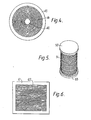
- the electrode shown in Figure 4 has been formed by coiling up a tape of the kind shown in Figure 1, in such a way that each edge of the tape lies on a single plane throughout the whole of its length, thereby producing a flat disc 41.
- the hole left on removal of the spindle used in the coiling operation has been filled with an inert plug 42.
- the layers of tape are held in place by a circular frame 43, which is a tight fit around the disc 41.
- a circular frame 43 which is a tight fit around the disc 41.
- disc electrodes we have used successfully have typically had over 50 turns in a disc of 24mm diameter and centre plug of 4mm diameter.
- the electrode may be used in the same manner as known porous electrodes formed of the same materials.
- two such porous electrodes may be used to form an electrolytic cell, being spaced apart for electrolyte to flow between them and each having a chamber on its outer surface to collect gaseous products of the electrolysis.
- a similar arrangement may be used in a fuel cell except that the gases, i.e fuel and oxygen or other oxidising agent, are fed to the chambers.
- the electrodes need not be of the same structure or materials, but both should be porous to enable the electrolyte to meet the gas within the pores of the electrode.
- the position of that interface may be stabilised by tapering the passages towards the electrolyte in the electrode or electrodes constructed according to the present invention.
- the tape 51 has been coiled such that the radius of the coil lies within the plane of the tape, whereas in the previous example, the radius of curvature was perpendicular to the tape.
- this configuration is basically unstable, and is more easily manufactured using a thicker tape. Although this cuts down the porosity of the electrode, this cylindrical shape is convenient in certain applications.
- the coiled tape is supported between a disc 52 and an annulus 53, between which are internal supports (not shown).
- the transverse channels with their sloping floors provide tapering passages extending between the outer and inner surfaces of the cylinder, the tapers of the passages being consistently outwards or inwards depending on the application.
- the cylindrical electrode may be used in conjunction with a similar coaxial electrode of larger diameter, with a space between them for the electrolyte, and a gas tight can surrounding them, the latter being spaced from the outer cylinder to form a chamber therebetween.
- the cell so formed is then used in essentially the same manner as the previous disc electrode, with a first gas being supplied to the inner cylinder and a second gas to the chamber between the outer cylinder and the can.
- the passages through the inner electrode should then taper outwards while the passages through the outer electrode should taper inwards, so that in both cases the passages taper towards the electrolyte side of the electrode.
- the electrode shown in Figure 6 has a flat rectangular shape, and is made up of an inert frame 61 supporting a large number of individual tapes 62 stacked one above the other in parallel layers.
- the tape used is substantially that shown in Figure 1, and the superimposed layers provide passages tapering from one side of the electrode to the other, as.
- Figures 2 and 3 show in detail.
Landscapes
- Chemical & Material Sciences (AREA)
- Chemical Kinetics & Catalysis (AREA)
- Electrochemistry (AREA)
- General Chemical & Material Sciences (AREA)
- Inert Electrodes (AREA)
- Fuel Cell (AREA)
Abstract
A porous gas diffusion electrode comprises a plurality of layers (6, 7, 8, 9, 10) of conducting tape having transverse channels, the layers of tape being superimposed one upon another with their edges aligned to form the two sides (12,13) of the electrode respectively. The open sides of the channels in one layer are thus closed by the overlying layer to form preferably tapered, transverse passages (11) extending from one side of the electrode to the other and thus providing the porosity of the electrode. The conducting layers may be formed from a single continuous tape which has been coiled to form a flat disc or a cylinder.
Description
- The invention relates to porous gas diffusion electrodes, and to their manufacture.
- Porous gas diffusion electrodes are used in certain fuel cells and other electrochemical apparatus involving reactions between a liquid electrolyte and a gaseous reactant or fuel. They are normally arranged with electrolyte supplied to one side and the gaseous reactant supplied to the other side, the electrodes being porous to allow penetration of both the electrolyte and the gas so that the electrolyte/gas interface occurs adjacent an electrode surface. This is most effective when it occurs within the interstices of the porous electrode rather than at an outer surface thereof, and to this end the porosity of gas diffusion electrodes is such that the electrolyte becomes drawn into the interstices by capillary action.
- Known electrodes include sintered metal electrodes wherein fine particles of metal, e.g platinum, are fused together while retaining much of their identity, thereby leaving a fine capillary porosity between them. However, the distance between the metal particles continually changes, both decreasing and increasing, as the passages traverse from one side of the electrode to the other. The degree of penetration of electrolyte is therefore difficult to predetermine by pore size, and will be optimum for only a limited number of the pores and limited electrolyte surface tensions. Consequently, penetration is generally controlled by providing pores of a size that will lead to complete filling of the interstices by capillary action, and to balance such action by the pressure of the gaseous reactant. However, without specialist equipment the sintered metal electrodes are difficult to manufacture to a desired pore size, and it is also difficult to maximise efficiency by controlling the position of the interfaces within such electrodes.
- According to the present invention, there is now provided a porous gas diffusion electrode having two sides for facing an electrolyte supply and a gas supply respectively, comprising a plurality of layers of tape of which at least some layers are shaped to provide transverse channels, the layers of tape being superimposed one upon another with their edges aligned to form the two sides of the electrode respectively and with the open--. sides of the channels in one layer being closed by the overlying layer to form transverse passages extending from one side of the electrode to the other thereby to provide the porosity of the electrode, at least one of the two layers which form each passage being electrically conducting; and means for holding the layers together.
- The electrode may be composed of a plurality of individual tapes laid one on top of another. Where these are all electrically conducting tapes in contact one with the next, further electrical interconnection may be unnecessary. However, the conducting tape may have a coating of some other material, e.g reaction catalysts, or the layers of tape may have layers of other materials interposed between them, and where such other materials are insulating, electrical interconnection between the conducting tapes is necessary.
- A preferred electrode is one wherein the conducting layers are formed from a single continuous tape which has been coiled, e.g to form a flat disc or a cylinder, or has been repeatedly folded, e.g zig-zag fashion, such that portions of the tape are overlaid in the electrode with a plurality of other portions spaced along the same tape. In this way, electrical continuity is preserved even when layers of insulating material are interposed between the folds of the conducting tape or an insulating tape is wound up together with the conducting tape to provide alternate conducting and insulating layers. However, for most purposes, it is preferred that adjacent layers are conducting, and in particular that adjacent layers are portions of the same conducting tape.
- The tape preferably has the transverse channels formed in one surface only, the reverse surface of the tape being substantially flat. The transverse passages formed between the channels of one layer and the flat surface of its overlying layer can then be of accurately controlled size and shape, this being determined by the size and shape of the channels. Where channels are provided in both surfaces, especially in the extreme case where the tape is simply a corrugated tape of constant .-thickness, there is the danger that the channels will become aligned, with the depending region of one layer fitting into the channel of the underlying layer and thereby reducing the size of the passage so formed, or even failing to provide any passage at all. This defect may be mitigated by providing a layer of flat tape between adjacent layers of corrugated tapes, tapes of the same conducting material being preferred, but other tapes, e.g tapes formed from catalytic materials, may be used.
- As described above in connection with known electrodes, the electrochemical reactions for which the electrodes are used, take place in the region of the triple interface between the electrolyte/gas meniscus and the electrode's conducting surface. The electrolyte is drawn into the transverse passages by capillary action, and the remainder of the passage is filled with gas. When the capillary action occurs in a passage of constant diameter, the surface tension will pull the electrolyte the full length of the passage unless balanced by the gas pressure at the meniscus. However, such a balance is unstable, as a slight increase in gas pressure or decrease in electrolyte surface tension, e.g because of a rise in temperature, will cause the passages to become empty of electrolyte, while a slight change in the conditions in the opposite direction will cause the passages to become completely full, both effects reducing the efficiency of the electrode.
- For reducing such instability, the gas side of the tape may be coated with a hydrophobic material. However this does not give the optimum meniscus shape.
- A preferred electrode is one in which the passages are tapered in a common direction from one side of the electrode to the other, the electrode then being used with its broad openings on the gas side and its narrow openings on the electrolyte side. The taper may be constant, of varying angle or even stepped. On account of the way it is formed, the passage will not be circular in cross section, and hence the diameters of each cross section will not be constant when measured in all mutually inclined directions. As will be appreciated, it is the shortest diameter which is critical in determining the amount of capillary action which will occur, and hence, provided the shortest diameter is tapered, no taper is required in the other directions.
- An electrode which is particularly preferred, is one in which tapered transverse passages are provided as a consequence of the transverse channels being of substantially rectangular sections which retain their width across the tape, but which are deeper at one side of the tape than the other. This provides a stable capillary action while avoiding unnecessary reduction in the area of the interface.
- According to a further aspect of the invention there is provided a method of constructing a porous gas diffusion electrode, which method comprises preparing a tape shaped with transverse channels formed in at least one surface, superimposing layers of the tape one above another with their edges aligned to form the two sides of the electrode respectively and with the open sides of the channels in one layer being closed by the overlying layer to form transverse passages extending from one side of the electrode to the other thereby to provide the porosity of the electrode; in the event that the channelled tape is electrically non-conducting, also inserting between the layers thereof tapes of conducting material and connecting together said tapes of conducting material; and securing the layers together to preserve the configuration of the electrode.
- A preferred method is one wherein the plurality of superimposed layers are provided by winding a continuous length of the channelled tape into a tight disc or cylindrical shaped coil, especially where the channelled tape is made of electrically conducting material and the coil is free from any tape of other material interposed between the layers of the conducting tape.
- Where all the layers are formed from tapes of the same conducting material, selection of the material for any given purpose will depend on what catalytic activity may be required of that material, and will be governed by essentially the same criteria as would be used to select the materials for electrodes of known construction. Thus for example, where a sintered platinum electrode is suitable for any particular reaction, an electrode according to the present invention may be made from platinum tape.
- Channelled tapes of most ductile materials may readily be made by drawing the selected material into a wire and passing the wire between rollers shaped to give the channelled surface while flattening the wire into a tape configuration.
- The invention is illustrated by reference to specific examples shown diagrammatically in the accompanying drawings, in which:
- Figure 1 is a sketch of a short length of tape used in the manufacture of electrodes according to the present invention,
- Figure 2 is a section through a small portion of an electrode, taken longitudinally with respect to the tapes,
- Figure 3 is a transverse section through the portion shown in longitudinal section in Figure 2,
- Figure 4 shows an electrode in the shape of a flat disc viewed from one side,
- Figure 5 shows a cylindrical electrode, and
- Figure 6 shows an electrode in the shape of a flat rectangular sheet.
- The tapes 1 shown in Figures 1 to 3 have a basic thin rectangular section 2 with
shallow channels 3 formed in one surface only, adjacent channels being separated by a narrow dividing wall 4. Thefloor 5 of each channel slopes from one edge of the tape to the other. In Figures 2 and 3, where tapes are shown forming a plurality oflayers lower layer 6 are closed by the flat surface of asecond layer 7 overlying it, to form a closed passage 11. Similarly, the channels of thatsecond layer 7 are closed by their overlying layer 8 to form similar passages, and likewise for the furtheroverlying layers - The electrode shown in Figure 4 has been formed by coiling up a tape of the kind shown in Figure 1, in such a way that each edge of the tape lies on a single plane throughout the whole of its length, thereby producing a
flat disc 41. The hole left on removal of the spindle used in the coiling operation has been filled with an inert plug 42. After coiling, the layers of tape are held in place by acircular frame 43, which is a tight fit around thedisc 41. For ease of illustration, only a few layers have been shown in the drawing, but in practice many more layers would be provided. For example, disc electrodes we have used successfully, have typically had over 50 turns in a disc of 24mm diameter and centre plug of 4mm diameter. - The electrode may be used in the same manner as known porous electrodes formed of the same materials. For example, two such porous electrodes may be used to form an electrolytic cell, being spaced apart for electrolyte to flow between them and each having a chamber on its outer surface to collect gaseous products of the electrolysis. A similar arrangement may be used in a fuel cell except that the gases, i.e fuel and oxygen or other oxidising agent, are fed to the chambers. In either case, the electrodes need not be of the same structure or materials, but both should be porous to enable the electrolyte to meet the gas within the pores of the electrode. The position of that interface may be stabilised by tapering the passages towards the electrolyte in the electrode or electrodes constructed according to the present invention.
- In manufacturing the cylindrical electrode shown in Figure 5, the
tape 51 has been coiled such that the radius of the coil lies within the plane of the tape, whereas in the previous example, the radius of curvature was perpendicular to the tape. With a thin tape, this configuration is basically unstable, and is more easily manufactured using a thicker tape. Although this cuts down the porosity of the electrode, this cylindrical shape is convenient in certain applications. The coiled tape is supported between adisc 52 and anannulus 53, between which are internal supports (not shown). The transverse channels with their sloping floors provide tapering passages extending between the outer and inner surfaces of the cylinder, the tapers of the passages being consistently outwards or inwards depending on the application. - The cylindrical electrode may be used in conjunction with a similar coaxial electrode of larger diameter, with a space between them for the electrolyte, and a gas tight can surrounding them, the latter being spaced from the outer cylinder to form a chamber therebetween. The cell so formed is then used in essentially the same manner as the previous disc electrode, with a first gas being supplied to the inner cylinder and a second gas to the chamber between the outer cylinder and the can. The passages through the inner electrode should then taper outwards while the passages through the outer electrode should taper inwards, so that in both cases the passages taper towards the electrolyte side of the electrode.
- The electrode shown in Figure 6 has a flat rectangular shape, and is made up of an
inert frame 61 supporting a large number ofindividual tapes 62 stacked one above the other in parallel layers. The tape used is substantially that shown in Figure 1, and the superimposed layers provide passages tapering from one side of the electrode to the other, as. Figures 2 and 3 show in detail.
Claims (14)
1. A porous gas diffusion electrode having two sides for facing an electrolyte supply and a gas supply respectively, comprising a plurality of layers of tape of which at least some layers are shaped to provide transverse channels, the layers of tape being superimposed one upon another with their edges aligned to form the two sides of the electrode respectively and with the open sides of the channels in one layer being closed by the overlying layer to form transverse passages extending from one side of the electrode to the other thereby to provide the porosity of the electrode, at least one of the two layers which form a passage being electrically conducting; and means for holding the layers together.
2. An electrode according to claim 1 wherein the transverse channels are formed in one surface only of a tape with the reverse side of the tape being substantially flat so that the transverse passages are formed between the channels of one layer and the flat surface of its overlying layer.
3. An electrode according to either claim 1 or claim 2 wherein the transverse passages are tapered in a common direction from one side of the electrode to the other.
4. An electrode according to claim 3 wherein the tapered transverse passages are provided as a consequence of the transverse channels being of substantially rectangular section which retain their width across the tape, but which are deeper at one side of the tape than the other.
5. An electrode according to any one of the preceding claims wherein the plurality of layers of tape is provided by a plurality of individual tapes laid one on top of the other.
6. An electrode according to claim 5 having a flat rectangular shaped derived from a plurality of individual tapes stacked one upon the other in parallel layers.
7. An electrode according to any one of claims 1 to 4 wherein the conducting layers are formed from a single continuous tape which has been coiled or repeatedly folded such that portions of the tape are overlaid in an electrode with a plurality of other portions spaced along the same tape.
8. An electrode according to claim 7 wherein adjacent layers are portions of the same conducting tape.
9. An electrode according to either claim 7 or claim 8 in the shape of a flat disc or a cylinder.
10. A method of constructing a porous gas diffusion electrode which method comprises preparing a tape shaped with transverse channels formed in at least one-surface, superimposing layers of the tape one above the other with their edges aligned to form the two sides of the electrode respectively and with the open channels in one layer being closed by the overlying layer to form transverse passages extending from one side of the electrode to the other thereby to provide the porosity of the electrode; in the event that the channelled tape is electrically non-conducting, also inserting between the layers thereof tapes of conducting material and connecting together said tapes of conducting material; and securing the layers together to preserve the configuration of the electrode.
ll. A method according to claim 10 wherein the superimposed layers are provided by winding a continuous length of the channelled tape into a tight disc or cylindrical shaped coil.
12. A method according to claim-il wherein the channelled tape is made of electrically conducting material and the coil is free from any tape or other material interposed between the layers of the conducting tape.
13. A method according to claim 10 wherein the superimposed layers are provided by stacking individual tapes one upon the other in parallel layers.
14. A method according to any one of claims 10 to 13 wherein the channelled tapes are made by drawing the material selected for the tape into a wire and passing the wire between rollers shaped to give the channelled surface while flattening the wire into a tape configuration.
Applications Claiming Priority (2)
| Application Number | Priority Date | Filing Date | Title |
|---|---|---|---|
| GB8000147 | 1980-01-03 | ||
| GB8000147 | 1980-01-03 |
Publications (1)
| Publication Number | Publication Date |
|---|---|
| EP0033416A1 true EP0033416A1 (en) | 1981-08-12 |
Family
ID=10510421
Family Applications (1)
| Application Number | Title | Priority Date | Filing Date |
|---|---|---|---|
| EP80304408A Withdrawn EP0033416A1 (en) | 1980-01-03 | 1980-12-05 | Gas diffusion electrodes |
Country Status (3)
| Country | Link |
|---|---|
| EP (1) | EP0033416A1 (en) |
| JP (1) | JPS56143674A (en) |
| AU (1) | AU6549680A (en) |
Cited By (3)
| Publication number | Priority date | Publication date | Assignee | Title |
|---|---|---|---|---|
| DE3532286A1 (en) * | 1985-09-11 | 1987-04-16 | Dobos Karoly Dr | ARRANGEMENT OF GAS DIFFUSION ELECTRODES AND METHOD FOR THE PRODUCTION OF GAS DIFFUSION ELECTRODES |
| DE19739019A1 (en) * | 1997-09-06 | 1999-03-11 | Forschungszentrum Juelich Gmbh | Spiral wound fuel cell device |
| US9112192B2 (en) | 2009-03-06 | 2015-08-18 | Brown University | Reactant delivery to a reactive surface in a channel |
Citations (1)
| Publication number | Priority date | Publication date | Assignee | Title |
|---|---|---|---|---|
| FR1382062A (en) * | 1962-12-05 | 1964-12-18 | Siemens Ag | gas diffusion electrode with oriented porosity and method of obtaining it |
-
1980
- 1980-12-05 EP EP80304408A patent/EP0033416A1/en not_active Withdrawn
- 1980-12-18 AU AU65496/80A patent/AU6549680A/en not_active Abandoned
-
1981
- 1981-01-05 JP JP6281A patent/JPS56143674A/en active Pending
Patent Citations (1)
| Publication number | Priority date | Publication date | Assignee | Title |
|---|---|---|---|---|
| FR1382062A (en) * | 1962-12-05 | 1964-12-18 | Siemens Ag | gas diffusion electrode with oriented porosity and method of obtaining it |
Non-Patent Citations (1)
| Title |
|---|
| NASA TECH. BRIEF, National Aeronautics and Space Administration, NTN-77/0472, Spring 1976 GSC-10984 "Metal Structures with parallel Pares", * Third column, lines 15-26; figure 3, first column, lines 1-8 * * |
Cited By (4)
| Publication number | Priority date | Publication date | Assignee | Title |
|---|---|---|---|---|
| DE3532286A1 (en) * | 1985-09-11 | 1987-04-16 | Dobos Karoly Dr | ARRANGEMENT OF GAS DIFFUSION ELECTRODES AND METHOD FOR THE PRODUCTION OF GAS DIFFUSION ELECTRODES |
| DE19739019A1 (en) * | 1997-09-06 | 1999-03-11 | Forschungszentrum Juelich Gmbh | Spiral wound fuel cell device |
| DE19739019C2 (en) * | 1997-09-06 | 2002-10-31 | Forschungszentrum Juelich Gmbh | Coiled fuel cell |
| US9112192B2 (en) | 2009-03-06 | 2015-08-18 | Brown University | Reactant delivery to a reactive surface in a channel |
Also Published As
| Publication number | Publication date |
|---|---|
| AU6549680A (en) | 1981-07-09 |
| JPS56143674A (en) | 1981-11-09 |
Similar Documents
| Publication | Publication Date | Title |
|---|---|---|
| US5650058A (en) | Electrolytic cell and capillary gap electrode for gas-developing or gas-consuming electrolytic reactions and electrolysis process therefor | |
| US6368383B1 (en) | Method of separating oxygen with the use of composite ceramic membranes | |
| DE3874498T2 (en) | COMBINATIONS OF ELECTROCHEMICAL CELLS OF LONG-TERM FORM. | |
| US4791035A (en) | Cell and current collector felt arrangement for solid oxide electrochemical cell combinations | |
| US4463068A (en) | Fuel cell and system for supplying electrolyte thereto with wick feed | |
| US6423436B1 (en) | Tubular electrochemical devices with lateral fuel aperatures for increasing active surface area | |
| JP4920133B2 (en) | Bipolar plates for fuel cells and fuel cells comprising such plates | |
| US5998056A (en) | Anode substrate for a high temperature fuel cell | |
| JPS6130385B2 (en) | ||
| JPS60163375A (en) | Electrochemical treatment method of liquid electrolyte | |
| RU2004137481A (en) | FUEL ELEMENT SYSTEM (OPTIONS) | |
| US20150372318A1 (en) | Fuel cell and method for manufacturing same | |
| WO2010015092A1 (en) | Mixed reactant flow-by fuel cell | |
| US11108059B2 (en) | Bipolar plate having a variable width of the reaction gas channels in the inlet region of the active region, fuel-cell stack and fuel-cell system having bipolar plates of this type, as well as a vehicle | |
| US20100086822A1 (en) | Fuel cell elements | |
| JPS60250563A (en) | Fuel battery | |
| EP0033416A1 (en) | Gas diffusion electrodes | |
| IT9021360A1 (en) | SOLID MARGIN SEALS FOR PHOSPHORIC ACID FUEL CELLS | |
| US7838169B2 (en) | Fuel cell cathode flow field | |
| EP0105592A1 (en) | Electrochemical power generator | |
| DE10117985A1 (en) | Fuel oxidation and electrolysis, involves using electrolysis fuel cell and reformer operation in composite foil Archimedes rolled coil spiral with open-cell uniform distancing to deliver medium | |
| US4539273A (en) | Electrode structure for electrochemical cell | |
| US3953237A (en) | Electric energy sources such as fuel cells and batteries | |
| US4225411A (en) | Support frame for electrolyte chambers in electrochemical cells | |
| US3560265A (en) | Galvanic cell with a materix electrode |
Legal Events
| Date | Code | Title | Description |
|---|---|---|---|
| PUAI | Public reference made under article 153(3) epc to a published international application that has entered the european phase |
Free format text: ORIGINAL CODE: 0009012 |
|
| AK | Designated contracting states |
Designated state(s): BE CH DE FR GB IT NL SE |
|
| RAP1 | Party data changed (applicant data changed or rights of an application transferred) |
Owner name: IMPERIAL CHEMICAL INDUSTRIES PLC |
|
| STAA | Information on the status of an ep patent application or granted ep patent |
Free format text: STATUS: THE APPLICATION IS DEEMED TO BE WITHDRAWN |
|
| 18D | Application deemed to be withdrawn |
Effective date: 19820705 |
|
| RIN1 | Information on inventor provided before grant (corrected) |
Inventor name: REDDISH, WILSON Inventor name: BLYTHE, ANTHONY REGINALD |