EP0032773B1 - A lock - Google Patents
A lock Download PDFInfo
- Publication number
- EP0032773B1 EP0032773B1 EP19810200059 EP81200059A EP0032773B1 EP 0032773 B1 EP0032773 B1 EP 0032773B1 EP 19810200059 EP19810200059 EP 19810200059 EP 81200059 A EP81200059 A EP 81200059A EP 0032773 B1 EP0032773 B1 EP 0032773B1
- Authority
- EP
- European Patent Office
- Prior art keywords
- lock
- catch
- unlocking
- locking
- lock according
- Prior art date
- Legal status (The legal status is an assumption and is not a legal conclusion. Google has not performed a legal analysis and makes no representation as to the accuracy of the status listed.)
- Expired
Links
- 230000008961 swelling Effects 0.000 claims description 19
- 230000000694 effects Effects 0.000 claims description 8
- 238000010521 absorption reaction Methods 0.000 claims description 2
- 239000007788 liquid Substances 0.000 claims description 2
- 230000000717 retained effect Effects 0.000 claims description 2
- XLYOFNOQVPJJNP-UHFFFAOYSA-N water Substances O XLYOFNOQVPJJNP-UHFFFAOYSA-N 0.000 description 8
- 230000002349 favourable effect Effects 0.000 description 2
- 238000010438 heat treatment Methods 0.000 description 2
- 238000003780 insertion Methods 0.000 description 2
- 230000037431 insertion Effects 0.000 description 2
- 238000005452 bending Methods 0.000 description 1
- 230000005540 biological transmission Effects 0.000 description 1
- 229920002678 cellulose Polymers 0.000 description 1
- 239000001913 cellulose Substances 0.000 description 1
- 238000010276 construction Methods 0.000 description 1
- 230000000881 depressing effect Effects 0.000 description 1
- 230000000994 depressogenic effect Effects 0.000 description 1
- 238000007654 immersion Methods 0.000 description 1
- 238000009423 ventilation Methods 0.000 description 1
Images

Classifications
-
- E—FIXED CONSTRUCTIONS
- E05—LOCKS; KEYS; WINDOW OR DOOR FITTINGS; SAFES
- E05B—LOCKS; ACCESSORIES THEREFOR; HANDCUFFS
- E05B77/00—Vehicle locks characterised by special functions or purposes
- E05B77/02—Vehicle locks characterised by special functions or purposes for accident situations
- E05B77/12—Automatic locking or unlocking at the moment of collision
-
- B—PERFORMING OPERATIONS; TRANSPORTING
- B60—VEHICLES IN GENERAL
- B60J—WINDOWS, WINDSCREENS, NON-FIXED ROOFS, DOORS, OR SIMILAR DEVICES FOR VEHICLES; REMOVABLE EXTERNAL PROTECTIVE COVERINGS SPECIALLY ADAPTED FOR VEHICLES
- B60J9/00—Devices not provided for in one of main groups B60J1/00 - B60J7/00
- B60J9/02—Entrance or exit closures other than windows, doors, or in roofs, e.g. emergency escape closures in vehicle bottom
-
- B—PERFORMING OPERATIONS; TRANSPORTING
- B60—VEHICLES IN GENERAL
- B60R—VEHICLES, VEHICLE FITTINGS, OR VEHICLE PARTS, NOT OTHERWISE PROVIDED FOR
- B60R22/00—Safety belts or body harnesses in vehicles
- B60R22/32—Devices for releasing in an emergency, e.g. after an accident ; Remote or automatic unbuckling devices
- B60R22/322—Devices for releasing in an emergency, e.g. after an accident ; Remote or automatic unbuckling devices using automatic actuating means
-
- Y—GENERAL TAGGING OF NEW TECHNOLOGICAL DEVELOPMENTS; GENERAL TAGGING OF CROSS-SECTIONAL TECHNOLOGIES SPANNING OVER SEVERAL SECTIONS OF THE IPC; TECHNICAL SUBJECTS COVERED BY FORMER USPC CROSS-REFERENCE ART COLLECTIONS [XRACs] AND DIGESTS
- Y10—TECHNICAL SUBJECTS COVERED BY FORMER USPC
- Y10S—TECHNICAL SUBJECTS COVERED BY FORMER USPC CROSS-REFERENCE ART COLLECTIONS [XRACs] AND DIGESTS
- Y10S24/00—Buckles, buttons, clasps
- Y10S24/30—Separable-fastener or required component thereof
-
- Y—GENERAL TAGGING OF NEW TECHNOLOGICAL DEVELOPMENTS; GENERAL TAGGING OF CROSS-SECTIONAL TECHNOLOGIES SPANNING OVER SEVERAL SECTIONS OF THE IPC; TECHNICAL SUBJECTS COVERED BY FORMER USPC CROSS-REFERENCE ART COLLECTIONS [XRACs] AND DIGESTS
- Y10—TECHNICAL SUBJECTS COVERED BY FORMER USPC
- Y10S—TECHNICAL SUBJECTS COVERED BY FORMER USPC CROSS-REFERENCE ART COLLECTIONS [XRACs] AND DIGESTS
- Y10S292/00—Closure fasteners
- Y10S292/65—Emergency or safety
-
- Y—GENERAL TAGGING OF NEW TECHNOLOGICAL DEVELOPMENTS; GENERAL TAGGING OF CROSS-SECTIONAL TECHNOLOGIES SPANNING OVER SEVERAL SECTIONS OF THE IPC; TECHNICAL SUBJECTS COVERED BY FORMER USPC CROSS-REFERENCE ART COLLECTIONS [XRACs] AND DIGESTS
- Y10—TECHNICAL SUBJECTS COVERED BY FORMER USPC
- Y10T—TECHNICAL SUBJECTS COVERED BY FORMER US CLASSIFICATION
- Y10T24/00—Buckles, buttons, clasps, etc.
- Y10T24/45—Separable-fastener or required component thereof [e.g., projection and cavity to complete interlock]
- Y10T24/45005—Separable-fastener or required component thereof [e.g., projection and cavity to complete interlock] with third detached member completing interlock [e.g., hook type]
- Y10T24/45079—Belt, strap, harness, etc.
- Y10T24/45084—Belt, strap, harness, etc. for safety belt buckle, strap, harness, etc.
-
- Y—GENERAL TAGGING OF NEW TECHNOLOGICAL DEVELOPMENTS; GENERAL TAGGING OF CROSS-SECTIONAL TECHNOLOGIES SPANNING OVER SEVERAL SECTIONS OF THE IPC; TECHNICAL SUBJECTS COVERED BY FORMER USPC CROSS-REFERENCE ART COLLECTIONS [XRACs] AND DIGESTS
- Y10—TECHNICAL SUBJECTS COVERED BY FORMER USPC
- Y10T—TECHNICAL SUBJECTS COVERED BY FORMER US CLASSIFICATION
- Y10T24/00—Buckles, buttons, clasps, etc.
- Y10T24/45—Separable-fastener or required component thereof [e.g., projection and cavity to complete interlock]
- Y10T24/45225—Separable-fastener or required component thereof [e.g., projection and cavity to complete interlock] including member having distinct formations and mating member selectively interlocking therewith
- Y10T24/45461—Interlocking portion actuated or released responsive to preselected condition [e.g., heat, pressure]
-
- Y—GENERAL TAGGING OF NEW TECHNOLOGICAL DEVELOPMENTS; GENERAL TAGGING OF CROSS-SECTIONAL TECHNOLOGIES SPANNING OVER SEVERAL SECTIONS OF THE IPC; TECHNICAL SUBJECTS COVERED BY FORMER USPC CROSS-REFERENCE ART COLLECTIONS [XRACs] AND DIGESTS
- Y10—TECHNICAL SUBJECTS COVERED BY FORMER USPC
- Y10T—TECHNICAL SUBJECTS COVERED BY FORMER US CLASSIFICATION
- Y10T292/00—Closure fasteners
- Y10T292/08—Bolts
- Y10T292/1043—Swinging
- Y10T292/1075—Operating means
- Y10T292/1082—Motor
-
- Y—GENERAL TAGGING OF NEW TECHNOLOGICAL DEVELOPMENTS; GENERAL TAGGING OF CROSS-SECTIONAL TECHNOLOGIES SPANNING OVER SEVERAL SECTIONS OF THE IPC; TECHNICAL SUBJECTS COVERED BY FORMER USPC CROSS-REFERENCE ART COLLECTIONS [XRACs] AND DIGESTS
- Y10—TECHNICAL SUBJECTS COVERED BY FORMER USPC
- Y10T—TECHNICAL SUBJECTS COVERED BY FORMER US CLASSIFICATION
- Y10T292/00—Closure fasteners
- Y10T292/57—Operators with knobs or handles
-
- Y—GENERAL TAGGING OF NEW TECHNOLOGICAL DEVELOPMENTS; GENERAL TAGGING OF CROSS-SECTIONAL TECHNOLOGIES SPANNING OVER SEVERAL SECTIONS OF THE IPC; TECHNICAL SUBJECTS COVERED BY FORMER USPC CROSS-REFERENCE ART COLLECTIONS [XRACs] AND DIGESTS
- Y10—TECHNICAL SUBJECTS COVERED BY FORMER USPC
- Y10T—TECHNICAL SUBJECTS COVERED BY FORMER US CLASSIFICATION
- Y10T74/00—Machine element or mechanism
- Y10T74/11—Tripping mechanism
Definitions
- the invention concerns a lock having a locking member displaceable between a locking position and a release position, wherein the lock is provided with a safety device for automatically unlocking the locking member upon a critical change of a given ambient condition, which safety device comprises at least one feeler member which is substantially unloaded prior to said change and which is responsive to the said change of condition and with an unlocking element, which by means of a spring is movable from a retracted rest position, wherein said element does not influence the locking member of the lock, to an operative position wherein said element displaces the locking member to the release position, the unlocking element being retained in the rest position by a catch operable by the feeler member, which catch is actuated when the feeler member responds to said change of condition and then releases the unlocking element.
- a drawback of this known device is that in case of a water emergency this will not function properly. The same will occur by high temperature.
- the lock according to the invention has the feature that the feeler member comprises a liquid-absorbing swelling body which presses the catch to the release position upon its swelling-up by liquid absorption.
- the lock is a buckle fastening with snap effect, in particular for a safety belt for motor-cars or the like, whereby the safety device together with the feeler member designed as a swelling body is accommodated in the buckle housing. If consequently the motor-car is submerged so that the swelling body comes into contact with water, the buckle fastening will be auomatically opened. As a result there is provided a compact construction, while moreover the feeler member is usually unloaded.
- the buckle fastening for a safety belt shown in Figures 1-5 has a flat housing 1 with a cover 2 screwed thereon, which housing is secured to a carrier plate 3 projecting with a lip portion 4 beyond the housing and having therein a fixing hole 5 for the buckle.
- the housing At the end facing away from the lip portion 4, the housing has an end wall 6 which releases between its lower edge and the housing bottom an insert slot 7 for a flat buckle tongue 8, having at the rear side a slotted hole 9 for attachment of the belt, not shown, and at its leading insert end a locking opening 10.
- a framework comprising flat longitudinal bars (11 (Fig. 2), which are rigidly connected besides by the end wall 6 also by transverse walls 12 and 13.
- a locking body 15 which has a guide tongue 16 for the buckle tongue 8 projecting rearwardly through the insert slot 7, at the bottom side a downwardly extending locking cam 17 fitting in the locking opening 10 of the buckle tongue 8 and at the top side a hook-shaped portion 18.
- On the locking body 15 acts a leaf spring 19 attached at one to the longitudinal bar 11, which spring keeps the locking body pressed in the closure position, wherein the locking cam 17 with its leading edge abuts against the bottom of the housing 1.
- buckle fastening with snap effect in that the buckle tongue 8 during insertion in the insert slot 7 finds guidance between the guide tongue 16 of the locking body 15 and the housing bottom and subsequently also underneath a pin 20, thereby pressing the cam 17 in an upward direction against the leaf spring 19 until this can fall in the locking opening 10 of the buckle tongue, engaging behind the leading edge of said opening 10 ( Figures 3 and 5).
- the locking body 15 serves a lever 22 supported pivotally about a pivot pin 21 in an opening in the transverse wall 13, said lever engaging with one end underneath the hook-shaped portion 18 of the locking body 1 5.
- a chamber 28 which is bounded at the outer side by a detachable back plate 29 constituting the back wall of the housing 1 and secured by a screw 29' and provided with holes 30, and at the inner side by an L-shaped slide 31, which slide 31 is guided by transverse guide pins 32 disposed between the longitudinal bars 11.
- a cylindrical swelling body 33 of a suitable cellulose which lies enclosed with slight play between the wall 29 and the slide 31 and, if desired as drawn, may be kept by a spring 34 in slightly clamped relationship.
- the guide pin 42 likewise forms the pivot pin for a two-armed rotary catch 43, the upper bent arm of which is inserted in an opening 44 of the plate 38 and the lower arm of which presses against the slide 31.
- the catch 43 thus prevents the unlocking rod 35 from sliding forwards through the effect of the spring 37, whereby the unlocking pawl retains the slide 31 in its rearward position under the effect of the spring pressure, in which position it abuts against the front guide pin 32. If, however, the buckle fastening comes to lie under water and this water can penetrate through openings 30 into the chamber 28, the swelling body 33 will rapidly swell and press the slide 31 forwardly through its expansion, so that the catch 43 is rotated away from the opening 44 and thus releases the unlocking rod 35. As a result the spring 37 can press the rod 35 forwardly and said rod can lift with its end the locking body 15 until the buckle fastening is opened.
- the housing cover 2 there is provided yet an access opening 46 covered by a detachable closure plate 45, enabling, after operation of the unlocking rod 35, to slide same back to its starting position and to position the catch 43 again in the locking position by means of a suitable tool.
- the safety device shown entirely by 61 in Figures 6 and 7 serves for unlocking a door lock or a motor-car door in case of calamity.
- the door lock may have a conventional design and is of the type that is lockable at the exterior with a key for locking the normal band crank or the like serving for operating the latch of the lock, whereby the lock at the inner side of the door has a sliding pin fitted with a hand knob, through which sliding pin the lock can be locked and unlocked from this side.
- the lock itself is not shown in Figures 6 and 7 since this may remain unchanged and may have any suitable design.
- sliding pin 62 with hand knob 63 is indicated, which is connected through a lever 64 to the door lock in such a way that in the depressed position of the knob 62 shown in full lines the lock is latched against operation from the outside, while in the dotted lifted position of the knob, said locking is removed.
- the lock with the lever 64 and the sliding pin 62 are accommodated conventionally in the door, while the knob 63 projects through an opening in the window opening edge 65 of the door.
- the device 61 forms a separate part which is adapted for assembly in the door underneath the sliding pin 62 in a suitable manner, not further indicated and consequently, if desired, can also be incorporated in an already existing door.
- the device 61 has a housing 66 with cover 67 and a framework positioned in the housing consisting of side plates 68 and a transverse wall 69 rigidly connected therewith.
- the swelling bady acts on the slide 31 guided on pins 32, against which slide is supported the one arm of the two-arm pivotally mounted catch 43 which on the other end engages in the opening 44 of the plate 38 guided between the pins 42 and 40, which plate is affixed to the rear end of the unlocking rod 35.
- Said rod 35 in the present case is guided axially slidably through fitting openings in the transverse wall 69 and the upper wall of the housing 66 and is under pressure of the helical spring 37 which lies enclosed between the transverse wall 69 and the sleeve 57 secured onto the rod 35.
- the diaphragm of the diaphragm box 75 will press the slide rod 77 inwardly in such a way that a given, predetermined critical temperature of the medium, the catch 83 is pressed by the sliding rod 77 from the hole 84 of the unlocking rod 82.
- the unlocking rod 82 is pressed upwardly by the spring 85, while the clip 87 entrains the pivoting catch 43 so that also the unlocking rod 35 is released and thus, as described in the above, the locking sliding pin 62 of the door lock is pressed upwardly to the unlocked position.
Landscapes
- Engineering & Computer Science (AREA)
- Mechanical Engineering (AREA)
- Automotive Seat Belt Assembly (AREA)
- Buckles (AREA)
- Lock And Its Accessories (AREA)
- Endoscopes (AREA)
- Supporting Of Heads In Record-Carrier Devices (AREA)
- Mechanical Operated Clutches (AREA)
Abstract
Description
- The invention concerns a lock having a locking member displaceable between a locking position and a release position, wherein the lock is provided with a safety device for automatically unlocking the locking member upon a critical change of a given ambient condition, which safety device comprises at least one feeler member which is substantially unloaded prior to said change and which is responsive to the said change of condition and with an unlocking element, which by means of a spring is movable from a retracted rest position, wherein said element does not influence the locking member of the lock, to an operative position wherein said element displaces the locking member to the release position, the unlocking element being retained in the rest position by a catch operable by the feeler member, which catch is actuated when the feeler member responds to said change of condition and then releases the unlocking element.
- In such an apparatus disclosed in German Offenlegungsschrift 27 50 335 for releasing a safety connection, use is made of feeler members which effect the unlocking via a control circuit and an electric magnet.
- A drawback of this known device is that in case of a water emergency this will not function properly. The same will occur by high temperature.
- It is the object of the invention to provide a lock of the above-described type, which is devoid of this drawback and which is very simple.
- The lock according to the invention has the feature that the feeler member comprises a liquid-absorbing swelling body which presses the catch to the release position upon its swelling-up by liquid absorption.
- According to an embodiment of the invention, the lock is a buckle fastening with snap effect, in particular for a safety belt for motor-cars or the like, whereby the safety device together with the feeler member designed as a swelling body is accommodated in the buckle housing. If consequently the motor-car is submerged so that the swelling body comes into contact with water, the buckle fastening will be auomatically opened. As a result there is provided a compact construction, while moreover the feeler member is usually unloaded.
- According to a different embodiment of the invention, the lock is a door lock, in particular for a motor-car door, of the type that is closable at one side through a key and at the other side having an actuating member, such as a sliding pin provided with a hand knob, by means of which the lock can be locked and unlocked from this side, whereby the unlocking element of the safety device being under spring pressure, upon actuation of said device, operates the actuating member of the door lock when said pin is in the lock latching position. If consequently the occupant of a motor-car has closed the door by depressing the lock sliding pins at the inside, said sliding pins, in case the motor-car is submerged, will be automatically pressed to the unlocking position by the swelling bodies of the associated safety devices, so that the doors can be opened from the outside in case of a rescue operation.
- According to the invention it is favourable when the safety device comprises besides the swelling body also as second feeler member a temperature-responsive member for unlocking the locking member of the lock. It is achieved thereby that also in case of fire the locking member is displaced to the release position, i.e. the buckle fastening will be opened or the door lock is unlocked. This embodiment with temperature increase-responsive safety device may also be applied e.g. to door locks of hotel rooms and the like, so that in case of fire these can be opened from the outside. It is observed in this respect that German Offenlegungsschrift 2,653,124 disclosed per se a temperature-responsive feeler member for a safety belt, wherein use is made of electric connections, which have the drawback that they can be easily put out of operation, while in the device according to the invention use is made of an entirely mechanical disconnecting mechanism.
- Some embodiments of the lock with safety device according to the invention will now be described, by way of example, with reference to the accompanying drawings, while also other preferred constructive features will be discussed.
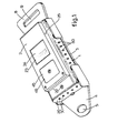
- Fig. 1 is a perspective view of a buckle fastening for a safety belt for motor-cars and the like, wherein the safety device is accommodated;
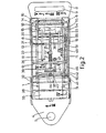
- Fig. 2 is a top view and partly a horizontal cross-section of the buckle fastening of Fig. 1;
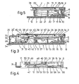
- Fig. 3 is a cross-section on the line III-II of Fig. 2;
- Fig. 4 is a cross-section on the line IV-IV of Fig. 2;
- Fig. 5 is a cross-section on the line V-V of Fig. 2;
- Fig. 6 is a vertical cross-section of a safety device for a motor-car door lock, of which only the locking sliding pin is drawn; and
- Fig. 7 is a cross-section on the line VII-VII of Fig. 6.
- The buckle fastening for a safety belt shown in Figures 1-5 has a
flat housing 1 with acover 2 screwed thereon, which housing is secured to acarrier plate 3 projecting with a lip portion 4 beyond the housing and having therein a fixing hole 5 for the buckle. At the end facing away from the lip portion 4, the housing has anend wall 6 which releases between its lower edge and the housing bottom aninsert slot 7 for aflat buckle tongue 8, having at the rear side aslotted hole 9 for attachment of the belt, not shown, and at its leading insert end alocking opening 10. - In the
housing 1 there is secured a framework comprising flat longitudinal bars (11 (Fig. 2), which are rigidly connected besides by theend wall 6 also bytransverse walls pivot openings 14 of thelongitudinal bars 11 there is rotatably supported alocking body 15, which has aguide tongue 16 for thebuckle tongue 8 projecting rearwardly through theinsert slot 7, at the bottom side a downwardly extendinglocking cam 17 fitting in the locking opening 10 of thebuckle tongue 8 and at the top side a hook-shaped portion 18. On thelocking body 15 acts aleaf spring 19 attached at one to thelongitudinal bar 11, which spring keeps the locking body pressed in the closure position, wherein thelocking cam 17 with its leading edge abuts against the bottom of thehousing 1. Thus, there is formed a buckle fastening with snap effect in that thebuckle tongue 8 during insertion in theinsert slot 7 finds guidance between theguide tongue 16 of thelocking body 15 and the housing bottom and subsequently also underneath apin 20, thereby pressing thecam 17 in an upward direction against theleaf spring 19 until this can fall in the locking opening 10 of the buckle tongue, engaging behind the leading edge of said opening 10 (Figures 3 and 5). For manually lifting thelocking body 15 serves alever 22 supported pivotally about apivot pin 21 in an opening in thetransverse wall 13, said lever engaging with one end underneath the hook-shapedportion 18 of thelocking body 1 5. Behind arectangular opening 23 cut out in thecover 2 there is present afinger pressure plate 24 which on the one end is rotatably secured to thecover 2 by apivot pin 25 and which carries at its opposite edge a downwardly projecting fork-shaped pressure member 26 which engages about the respective end of thelever 22. Between the bottom of thehousing 1 and thefinger pressure plate 24 there is positioned a pressure spring 27 (Fig. 3) which keeps said plate pressed against the bottom side of thecover 2. By a pressure with the finger on theplate 24 against the action of thespring 27 it is thus possible to rotate thelever 22 through thepressure member 26 to a position wherein said lever, by means of the hook-shapedportion 18, swivels thelocking body 15 to the unlocked position releasing thebuckle tongue 8. - The above described parts of the buckle fastening are of an embodiment conventional for such fastenings.
- According to the invention there is now accommodated in the buckle housing 1 a safety device ensuring that the
locking body 15 automatically unlocks thebuckle tongue 8 when the buckle housing is exposed to the effect of water or a high temperature. - At the back side of the
buckle housing 1 there is formed achamber 28 which is bounded at the outer side by adetachable back plate 29 constituting the back wall of thehousing 1 and secured by a screw 29' and provided withholes 30, and at the inner side by an L-shaped slide 31, whichslide 31 is guided bytransverse guide pins 32 disposed between thelongitudinal bars 11. In thechamber 28 there is positioned acylindrical swelling body 33 of a suitable cellulose which lies enclosed with slight play between thewall 29 and theslide 31 and, if desired as drawn, may be kept by aspring 34 in slightly clamped relationship. Upon removal of theback plate 29, thechamber 28 is accessible for insertion of theswelling body 33. - In fitting holes in the
transverse walls unlocking rod 35 which in the retracted rest position shown in Figures 2 and 3 engages with its beveled leadingend 36 with slight play underneath the edge of the hook-shaped portion 18 of thelocking body 15. About therod 35 there is positioned ahelical spring 37 which on the one end finds support against thetransverse wall 12 and on the other end against asleeve 57 fixed onto therod 35, thus trying to press therod 35 forwardly. At the rear end of therod 35 there is affixed aplate 38 which is guided between anupper guide roller 40 carried bysupports 39 and two lower guide rollers orpins longitudinal bars 11. Theguide pin 42 likewise forms the pivot pin for a two-armedrotary catch 43, the upper bent arm of which is inserted in anopening 44 of theplate 38 and the lower arm of which presses against theslide 31. Thecatch 43 thus prevents the unlockingrod 35 from sliding forwards through the effect of thespring 37, whereby the unlocking pawl retains theslide 31 in its rearward position under the effect of the spring pressure, in which position it abuts against thefront guide pin 32. If, however, the buckle fastening comes to lie under water and this water can penetrate throughopenings 30 into thechamber 28, theswelling body 33 will rapidly swell and press theslide 31 forwardly through its expansion, so that thecatch 43 is rotated away from the opening 44 and thus releases theunlocking rod 35. As a result thespring 37 can press therod 35 forwardly and said rod can lift with its end thelocking body 15 until the buckle fastening is opened. - In the
housing cover 2 there is provided yet an access opening 46 covered by a detachable closure plate 45, enabling, after operation of the unlockingrod 35, to slide same back to its starting position and to position thecatch 43 again in the locking position by means of a suitable tool. - The safety device accommodated in the
buckle housing 1 furthermore comprises a bimetal element 47 (Fig. 4), which is fixed with its ends in aholder 48, which holder is secured byscrews 49 against the outer side of one of thelongitudinal rods 11, so that the holder and the bimetal lie incorporated in the space between thelongitudinal rod 11 and the adjacent housing sidewall. Furthermore, twonuts 50 are welded against therod 11 and wherein are screwed adjustingscrews 51 pressing against the ends of the holder, enabling to accurately adjust the device by a slight bending of theelongate holder 48. Thebimetal element 47 carries in the center a downwardly extending catch in the form of apin 52. Underneath thebimetal element 47 there extends a secondunlocking rod 53 which is guided slidably in holes in the ends of thetransverse walls beveled end 54 with some play underneath asupport member 55 of thelocking body 15 projecting through the pivot opening 14 of thelongitudinal bar 11. Figure 4 shows that said opening 14 is formed in such a way that thesupport member 55 is adapted to perform a pivoting movement therein. About theunlocking rod 53 there is' positioned ahelical spring 56 which lies enclosed between thetransverse wall 13 and asleeve 58 affixed onto therod 53 and thus trying to press therod 53 forwardly. In the rest position shown theunlocking rod 53, however, is locked in that thelocking pin 52 is inserted in atransverse bore hole 59 of therod 53. - The
bimetal element 47 is designed in such a way that when heated said element deflects upwardly in the center, thereby pulling thelocking pin 52 from thehole 59 of theunlocking rod 53 so that at a given strongly increased critical ambient temperature, thepin 52 releases theunlocking rod 53 so that thespring 56 can press said rod with itsend 54 underneath theportion 55 of thelocking body 15 for unlocking the buckle fastening. In the sidewall of thehousing 1 extending along thebimetal 47 there are provided ventilation holes 60 (Fig. 1 - The safety device shown entirely by 61 in Figures 6 and 7 serves for unlocking a door lock or a motor-car door in case of calamity. The door lock may have a conventional design and is of the type that is lockable at the exterior with a key for locking the normal band crank or the like serving for operating the latch of the lock, whereby the lock at the inner side of the door has a sliding pin fitted with a hand knob, through which sliding pin the lock can be locked and unlocked from this side. The lock itself is not shown in Figures 6 and 7 since this may remain unchanged and may have any suitable design. However, the above mentioned sliding
pin 62 withhand knob 63 is indicated, which is connected through alever 64 to the door lock in such a way that in the depressed position of theknob 62 shown in full lines the lock is latched against operation from the outside, while in the dotted lifted position of the knob, said locking is removed. The lock with thelever 64 and thesliding pin 62 are accommodated conventionally in the door, while theknob 63 projects through an opening in thewindow opening edge 65 of the door. - The
device 61 forms a separate part which is adapted for assembly in the door underneath thesliding pin 62 in a suitable manner, not further indicated and consequently, if desired, can also be incorporated in an already existing door. - The
device 61 has ahousing 66 with cover 67 and a framework positioned in the housing consisting ofside plates 68 and atransverse wall 69 rigidly connected therewith. - The
safety device 61, as regards its operation in case of immersion in water has a design analogous to that of the device described on the basis of Figures 2 and 3, while in Figures 6 and 7 identical parts are indicated with the same reference numerals as in Figures 2 and 3. Thedevice 61 again has aswelling body 33 accommodated in achamber 28, which chamber in the present case is accessible by anaccess door 70 provided in the cover 67 and projecting along some distance inwardly, while furthermoreholes 30 provided in the housing wall terminate in thechamber 28. The swelling bady acts on theslide 31 guided onpins 32, against which slide is supported the one arm of the two-arm pivotally mountedcatch 43 which on the other end engages in theopening 44 of theplate 38 guided between thepins unlocking rod 35. Saidrod 35 in the present case is guided axially slidably through fitting openings in thetransverse wall 69 and the upper wall of thehousing 66 and is under pressure of thehelical spring 37 which lies enclosed between thetransverse wall 69 and thesleeve 57 secured onto therod 35. The end of the unlockingrod 35 in this case projects from thehousing 66 in outward direction and carries astop head 71 secured thereon, which in the drawn rest position of the unlockingrod 35 lies with slight play underneath the bottom end of thelock sliding pin 62 respectively thelever 64 pivotally secured thereon. It will be clear that in case through expansion of the swellingbody 33 thecatch 43 releases the unlockingrod 35, said rod through the effect of thespring 37 will be urged upwardly, thereby forcing with itshead 71 thelock sliding pin 62 to the dotted unlocking position. On the outwardly projecting end portion of the unlockingrod 35 there is mounted yet adrip cap 72 engaging about thehousing 66, while on the cover 67 above theaccess door 70 there is attached a projectingdrip edge 72a to prevent any rain or wash water seeping into the door from attaining the swellingbody 33. - The
safety device 61 is designed with a temperature-responsive member which in the present case comprises acontainer 73 filled with a medium expandable upon heating and which is connected through apipe 74 to adiaphragm box 75 mounted against the side of thehousing 66 of a known per se design. The container orfeeler 73 may be secured in a suitable place against the inner wall of the respective motor-car door, preferably behind an opening in said door wall covered by a grid or the like. The diaphragm of thediaphragm box 75 acts through atransmission mechanism 76 on a slidingrod 77 conducted through the housing wall into the housing. Against the bottom of thehousing 66 there is secured anassembly plate 78 which has upright supports 79 fitted with a guide hole for guidance of the slidingrod 77 andsimilar supports rod 77 there is mounted acatch 83 which with its bent back end is inserted into atransverse hole 84 of the unlocking rod 82, thereby retaining said rod in the rest position drawn. On the unlocking rod 82 there acts again ahelical spring 85 which lies enclosed between thesupport 81 and a sleeve 86 secured on the rod 82 and which tries to press the rod 82 upwardly. At the bottom end of the unlocking rod 82 there is secured aclip 87 which in the rest position drawn engages with some play about the end of thecatch 43 facing towards theslide 31. On theassembly plate 78 there is formed yet astop shoulder 88 which limits the upward movement of the unlocking rod 82. - When for instance in case of a motor-car fire the medium in the
container 73 expands through heating, the diaphragm of thediaphragm box 75 will press theslide rod 77 inwardly in such a way that a given, predetermined critical temperature of the medium, thecatch 83 is pressed by the slidingrod 77 from thehole 84 of the unlocking rod 82. Thus the unlocking rod 82 is pressed upwardly by thespring 85, while theclip 87 entrains the pivotingcatch 43 so that also the unlockingrod 35 is released and thus, as described in the above, thelocking sliding pin 62 of the door lock is pressed upwardly to the unlocked position. - Although the safety device described in the above for unlocking or opening a lock is suitable in particular for application in combination with a buckle fastening for a safety belt or the like of a motor-car door, also other favourable applications are conceivable. For instance, the safety device may be accommodated in the buckle fastening between the harness of a parachute and the parachute lines, so that this fastening will be automatically opened when the parachutist arrives in the water. A temperature-responsive member in that case is not necessary. The latter again is the case though upon application of the safety device described in combination with a door lock closable at the inside by a latch or the like of e.g. a door of a hotel room, so that in case of fire this locking is automatically removed. In general, the swelling body may be omitted in the latter application.
Claims (13)
Priority Applications (1)
| Application Number | Priority Date | Filing Date | Title |
|---|---|---|---|
| AT81200059T ATE8367T1 (en) | 1980-01-18 | 1981-01-16 | LOCK. |
Applications Claiming Priority (2)
| Application Number | Priority Date | Filing Date | Title |
|---|---|---|---|
| NL8000322 | 1980-01-18 | ||
| NL8000322A NL8000322A (en) | 1980-01-18 | 1980-01-18 | KEY LOCK. |
Publications (2)
| Publication Number | Publication Date |
|---|---|
| EP0032773A1 EP0032773A1 (en) | 1981-07-29 |
| EP0032773B1 true EP0032773B1 (en) | 1984-07-11 |
Family
ID=19834698
Family Applications (1)
| Application Number | Title | Priority Date | Filing Date |
|---|---|---|---|
| EP19810200059 Expired EP0032773B1 (en) | 1980-01-18 | 1981-01-16 | A lock |
Country Status (6)
| Country | Link |
|---|---|
| US (1) | US4441236A (en) |
| EP (1) | EP0032773B1 (en) |
| JP (1) | JPS56108475A (en) |
| AT (1) | ATE8367T1 (en) |
| DE (1) | DE3164630D1 (en) |
| NL (1) | NL8000322A (en) |
Cited By (2)
| Publication number | Priority date | Publication date | Assignee | Title |
|---|---|---|---|---|
| CN107594771A (en) * | 2017-09-15 | 2018-01-19 | 无锡市湖昌机械制造有限公司 | Car belt inserted sheet with igniter |
| WO2023036367A1 (en) | 2021-09-10 | 2023-03-16 | Kiekert Aktiengesellschaft | Plastic housing for automotive applications |
Families Citing this family (22)
| Publication number | Priority date | Publication date | Assignee | Title |
|---|---|---|---|---|
| US4526934A (en) * | 1982-03-19 | 1985-07-02 | Bridgestone Tire Company Limited | Branched styrene-butadiene copolymers and pneumatic tires using the same |
| US4555831A (en) * | 1982-05-07 | 1985-12-03 | Uwe Otzen | Catch for safety belts of air, water, and land transport means |
| US4637101A (en) * | 1983-01-05 | 1987-01-20 | Fiedler Leslie C | Actuator with osmotic pressure actuation |
| GB8405249D0 (en) * | 1984-02-29 | 1984-04-04 | Secr Defence | Harness fasteners |
| US4715096A (en) * | 1986-07-10 | 1987-12-29 | Fleming Joseph A | Thermally actuated seat belt fastener |
| AT386992B (en) * | 1986-08-08 | 1988-11-10 | Wartecker Otto | ADDITIONAL DEVICE FOR MOTOR VEHICLE SAFETY BELTS |
| KR900001050Y1 (en) * | 1987-05-29 | 1990-02-15 | 강충석 | Buckle of car safety belt with starting switch |
| US4815177A (en) * | 1988-02-09 | 1989-03-28 | Mackew James | Automatic time-delayed release buckle |
| IT1240910B (en) * | 1990-03-13 | 1993-12-23 | Andrea Garboli | ELECTRIC-MECHANICAL DEVICE OPERATED BY AN ELECTRONIC CONTROL UNIT FOR THE AUTOMATIC RELEASE, IN ADDITION TO MANUAL, OF THE SAFETY BELTS INSTALLED ON THE VEHICLES |
| US5484176A (en) * | 1994-05-20 | 1996-01-16 | Motus, Inc. | Latch mechanism |
| JP3099865B2 (en) | 1995-01-11 | 2000-10-16 | 日本工機株式会社 | Parachute separation equipment |
| DE29510590U1 (en) * | 1995-06-29 | 1996-11-07 | Trw Repa Gmbh, 73553 Alfdorf | Seat belt buckle in vehicles |
| JP3730807B2 (en) * | 1999-05-21 | 2006-01-05 | アルプス電気株式会社 | Submergence detection power window device |
| NL1034480C2 (en) * | 2007-10-05 | 2009-04-07 | Bin Innovations Bv | Seat belt release mechanism for use in passenger vehicle e.g. airplane, has pin movable over housing through spring, and release button to operate pin to move over housing |
| NL2002161C (en) * | 2008-10-31 | 2010-05-04 | Bin Innovations Bv | UNLOCK MECHANISM. |
| DE202009017667U1 (en) | 2009-12-26 | 2011-05-05 | BROSE SCHLIEßSYSTEME GMBH & CO. KG | Motor vehicle lock arrangement |
| US8631545B2 (en) * | 2010-07-15 | 2014-01-21 | Carleton Life Support Systems, Inc. | Water activated ejector mechanism for rotary buckle assembly |
| CN102434040B (en) * | 2011-09-29 | 2013-08-07 | 奇瑞汽车股份有限公司 | Lock catch opening counterweight device |
| US9084452B2 (en) | 2012-08-06 | 2015-07-21 | Carleton Technologies, Inc. | Water activated restraint release system |
| US9611675B2 (en) | 2014-05-23 | 2017-04-04 | Brose Schliesssysteme Gmbh & Co. Kg | Motor vehicle door lock arrangement |
| CN103921756B (en) * | 2014-04-20 | 2016-04-20 | 张卫 | Overboard self opening safety strap lock |
| EP2980341B1 (en) * | 2014-07-31 | 2019-11-06 | Brose Schliesssysteme GmbH & Co. KG | Motor vehicle door lock arrangement |
Citations (11)
| Publication number | Priority date | Publication date | Assignee | Title |
|---|---|---|---|---|
| NL47301C (en) * | 1900-01-01 | |||
| FR663225A (en) * | 1927-10-31 | 1929-08-19 | Device for unlocking door and window closures in the event of danger, in particular in the event of explosions | |
| GB515950A (en) * | 1938-06-15 | 1939-12-19 | Alfred Charles Hall Armstrong | Improvements in or relating to emergency exit arrangements for vehicle and aircraft bodies |
| FR1547367A (en) * | 1965-11-15 | 1968-11-29 | Safety buckle for belts | |
| FR1554574A (en) * | 1966-02-19 | 1969-01-24 | ||
| FR1565373A (en) * | 1967-11-23 | 1969-05-02 | ||
| FR2244424A1 (en) * | 1973-09-21 | 1975-04-18 | Barbe Guy | |
| FR2264691A1 (en) * | 1974-03-20 | 1975-10-17 | Caradec Alain | Safety release device for safety belt - has attachment plates secured by blocks disintegrating due to heat or water |
| FR2366030A1 (en) * | 1976-09-30 | 1978-04-28 | Merli Gian Franco | Emergency release for vehicle safety belt - uses decelerometer signals with time delay to energise electromagnet and pull catch from buckle |
| DE2653124A1 (en) * | 1976-11-23 | 1978-05-24 | Porsche Ag | Seat-belt emergency release - has lock with electromagnets activated from body-mounted thermionic converter signals |
| DE2750335A1 (en) * | 1976-11-12 | 1978-05-24 | Heinzmann Erich | DEVICE FOR RELEASING A FUSE CONNECTION |
Family Cites Families (4)
| Publication number | Priority date | Publication date | Assignee | Title |
|---|---|---|---|---|
| US3146027A (en) * | 1962-07-20 | 1964-08-25 | Ragnar W Winberg | Automobile seat belt delayed action release |
| US3675281A (en) * | 1970-04-16 | 1972-07-11 | Allied Chem | Seat belt buckle assembly |
| FR2315878A2 (en) * | 1974-12-18 | 1977-01-28 | Lasserre Athanase | Safety belt with arm which moves automatically - rises from concealed position when someone sits on seat |
| FR2317947A1 (en) * | 1975-07-17 | 1977-02-11 | Bouju Michel | SAFETY BELT SAFETY DEVICE |
-
1980
- 1980-01-18 NL NL8000322A patent/NL8000322A/en not_active Application Discontinuation
-
1981
- 1981-01-16 EP EP19810200059 patent/EP0032773B1/en not_active Expired
- 1981-01-16 DE DE8181200059T patent/DE3164630D1/en not_active Expired
- 1981-01-16 AT AT81200059T patent/ATE8367T1/en not_active IP Right Cessation
- 1981-01-19 US US06/226,534 patent/US4441236A/en not_active Expired - Fee Related
- 1981-01-19 JP JP627581A patent/JPS56108475A/en active Pending
Patent Citations (11)
| Publication number | Priority date | Publication date | Assignee | Title |
|---|---|---|---|---|
| NL47301C (en) * | 1900-01-01 | |||
| FR663225A (en) * | 1927-10-31 | 1929-08-19 | Device for unlocking door and window closures in the event of danger, in particular in the event of explosions | |
| GB515950A (en) * | 1938-06-15 | 1939-12-19 | Alfred Charles Hall Armstrong | Improvements in or relating to emergency exit arrangements for vehicle and aircraft bodies |
| FR1547367A (en) * | 1965-11-15 | 1968-11-29 | Safety buckle for belts | |
| FR1554574A (en) * | 1966-02-19 | 1969-01-24 | ||
| FR1565373A (en) * | 1967-11-23 | 1969-05-02 | ||
| FR2244424A1 (en) * | 1973-09-21 | 1975-04-18 | Barbe Guy | |
| FR2264691A1 (en) * | 1974-03-20 | 1975-10-17 | Caradec Alain | Safety release device for safety belt - has attachment plates secured by blocks disintegrating due to heat or water |
| FR2366030A1 (en) * | 1976-09-30 | 1978-04-28 | Merli Gian Franco | Emergency release for vehicle safety belt - uses decelerometer signals with time delay to energise electromagnet and pull catch from buckle |
| DE2750335A1 (en) * | 1976-11-12 | 1978-05-24 | Heinzmann Erich | DEVICE FOR RELEASING A FUSE CONNECTION |
| DE2653124A1 (en) * | 1976-11-23 | 1978-05-24 | Porsche Ag | Seat-belt emergency release - has lock with electromagnets activated from body-mounted thermionic converter signals |
Cited By (3)
| Publication number | Priority date | Publication date | Assignee | Title |
|---|---|---|---|---|
| CN107594771A (en) * | 2017-09-15 | 2018-01-19 | 无锡市湖昌机械制造有限公司 | Car belt inserted sheet with igniter |
| WO2023036367A1 (en) | 2021-09-10 | 2023-03-16 | Kiekert Aktiengesellschaft | Plastic housing for automotive applications |
| DE102021123442A1 (en) | 2021-09-10 | 2023-03-16 | Kiekert Aktiengesellschaft | Plastic housing for automotive applications |
Also Published As
| Publication number | Publication date |
|---|---|
| US4441236A (en) | 1984-04-10 |
| NL8000322A (en) | 1981-08-17 |
| JPS56108475A (en) | 1981-08-28 |
| DE3164630D1 (en) | 1984-08-16 |
| EP0032773A1 (en) | 1981-07-29 |
| ATE8367T1 (en) | 1984-07-15 |
Similar Documents
| Publication | Publication Date | Title |
|---|---|---|
| US4441236A (en) | Safety lock | |
| KR890001457Y1 (en) | Door handle latch and lock mechanism | |
| US4006121A (en) | Door latch mechanism controlling switch in microwave oven or the like | |
| US4593945A (en) | Oven latch assembly | |
| US4889373A (en) | Door handle unit | |
| CA1151247A (en) | Door latching assembly | |
| US6135013A (en) | Pressure cooker with safety device to prevent the lid from turning | |
| US3954023A (en) | Automatic lock and release mechanism for opening movable-slat windows | |
| GB2133455A (en) | Door Latch | |
| US4720611A (en) | Electro-manual drawer latch | |
| EP0533635B1 (en) | A device for opening the port-hole door of a domestic washing machine | |
| JP2000167271A (en) | Blade sharpener, assembly therefor and blade sheath | |
| US5154460A (en) | Motor vehicle door lock | |
| US3346288A (en) | Safety lock means | |
| US4749835A (en) | Mechanism for closing microwave oven door | |
| EP0940107B1 (en) | Pressure-cooker with safety device for the cover | |
| US4537431A (en) | Locking device, particularly for a spare wheel cradle | |
| GB2094556A (en) | An electrical domestic appliance provided with a lockable door and an electrical switch | |
| JP2520147Y2 (en) | Storage door opening / closing mechanism | |
| JP5193642B2 (en) | Latch device | |
| GB2137686A (en) | Security bolt | |
| JPS603901Y2 (en) | cabinet locking device | |
| JP4130857B2 (en) | Locking device | |
| JPS6119575Y2 (en) | ||
| JPH0335816Y2 (en) |
Legal Events
| Date | Code | Title | Description |
|---|---|---|---|
| PUAI | Public reference made under article 153(3) epc to a published international application that has entered the european phase |
Free format text: ORIGINAL CODE: 0009012 |
|
| AK | Designated contracting states |
Designated state(s): AT BE CH DE FR GB IT LU NL SE |
|
| 17P | Request for examination filed |
Effective date: 19820118 |
|
| ITF | It: translation for a ep patent filed | ||
| GRAA | (expected) grant |
Free format text: ORIGINAL CODE: 0009210 |
|
| AK | Designated contracting states |
Designated state(s): AT BE CH DE FR GB IT LI LU NL SE |
|
| REF | Corresponds to: |
Ref document number: 8367 Country of ref document: AT Date of ref document: 19840715 Kind code of ref document: T |
|
| REF | Corresponds to: |
Ref document number: 3164630 Country of ref document: DE Date of ref document: 19840816 |
|
| ET | Fr: translation filed | ||
| PG25 | Lapsed in a contracting state [announced via postgrant information from national office to epo] |
Ref country code: LU Free format text: LAPSE BECAUSE OF NON-PAYMENT OF DUE FEES Effective date: 19850131 |
|
| PGFP | Annual fee paid to national office [announced via postgrant information from national office to epo] |
Ref country code: DE Payment date: 19850228 Year of fee payment: 5 |
|
| PLBE | No opposition filed within time limit |
Free format text: ORIGINAL CODE: 0009261 |
|
| STAA | Information on the status of an ep patent application or granted ep patent |
Free format text: STATUS: NO OPPOSITION FILED WITHIN TIME LIMIT |
|
| 26N | No opposition filed | ||
| PGFP | Annual fee paid to national office [announced via postgrant information from national office to epo] |
Ref country code: AT Payment date: 19860115 Year of fee payment: 6 |
|
| PG25 | Lapsed in a contracting state [announced via postgrant information from national office to epo] |
Ref country code: AT Effective date: 19870116 |
|
| PG25 | Lapsed in a contracting state [announced via postgrant information from national office to epo] |
Ref country code: SE Effective date: 19870117 |
|
| PG25 | Lapsed in a contracting state [announced via postgrant information from national office to epo] |
Ref country code: LI Effective date: 19870131 Ref country code: CH Effective date: 19870131 |
|
| PGFP | Annual fee paid to national office [announced via postgrant information from national office to epo] |
Ref country code: NL Payment date: 19870131 Year of fee payment: 7 |
|
| BERE | Be: lapsed |
Owner name: BRON JOSE Effective date: 19870131 |
|
| GBPC | Gb: european patent ceased through non-payment of renewal fee | ||
| PG25 | Lapsed in a contracting state [announced via postgrant information from national office to epo] |
Ref country code: FR Free format text: LAPSE BECAUSE OF NON-PAYMENT OF DUE FEES Effective date: 19870930 |
|
| REG | Reference to a national code |
Ref country code: CH Ref legal event code: PL |
|
| PG25 | Lapsed in a contracting state [announced via postgrant information from national office to epo] |
Ref country code: DE Effective date: 19871001 |
|
| REG | Reference to a national code |
Ref country code: FR Ref legal event code: ST |
|
| PG25 | Lapsed in a contracting state [announced via postgrant information from national office to epo] |
Ref country code: NL Effective date: 19880801 |
|
| NLV4 | Nl: lapsed or anulled due to non-payment of the annual fee | ||
| PG25 | Lapsed in a contracting state [announced via postgrant information from national office to epo] |
Ref country code: GB Effective date: 19881118 |
|
| PG25 | Lapsed in a contracting state [announced via postgrant information from national office to epo] |
Ref country code: BE Effective date: 19890131 |
|
| EUG | Se: european patent has lapsed |
Ref document number: 81200059.4 Effective date: 19870923 |