EP0032499B1 - Optical illumination and distortion compensator - Google Patents
Optical illumination and distortion compensator Download PDFInfo
- Publication number
- EP0032499B1 EP0032499B1 EP80901517A EP80901517A EP0032499B1 EP 0032499 B1 EP0032499 B1 EP 0032499B1 EP 80901517 A EP80901517 A EP 80901517A EP 80901517 A EP80901517 A EP 80901517A EP 0032499 B1 EP0032499 B1 EP 0032499B1
- Authority
- EP
- European Patent Office
- Prior art keywords
- mirror
- curved
- screen
- image
- visual display
- Prior art date
- Legal status (The legal status is an assumption and is not a legal conclusion. Google has not performed a legal analysis and makes no representation as to the accuracy of the status listed.)
- Expired
Links
Images


Classifications
-
- G—PHYSICS
- G09—EDUCATION; CRYPTOGRAPHY; DISPLAY; ADVERTISING; SEALS
- G09B—EDUCATIONAL OR DEMONSTRATION APPLIANCES; APPLIANCES FOR TEACHING, OR COMMUNICATING WITH, THE BLIND, DEAF OR MUTE; MODELS; PLANETARIA; GLOBES; MAPS; DIAGRAMS
- G09B9/00—Simulators for teaching or training purposes
- G09B9/02—Simulators for teaching or training purposes for teaching control of vehicles or other craft
- G09B9/08—Simulators for teaching or training purposes for teaching control of vehicles or other craft for teaching control of aircraft, e.g. Link trainer
- G09B9/30—Simulation of view from aircraft
- G09B9/32—Simulation of view from aircraft by projected image
- G09B9/326—Simulation of view from aircraft by projected image the image being transformed by optical means
-
- G—PHYSICS
- G02—OPTICS
- G02B—OPTICAL ELEMENTS, SYSTEMS OR APPARATUS
- G02B13/00—Optical objectives specially designed for the purposes specified below
- G02B13/08—Anamorphotic objectives
-
- G—PHYSICS
- G02—OPTICS
- G02B—OPTICAL ELEMENTS, SYSTEMS OR APPARATUS
- G02B27/00—Optical systems or apparatus not provided for by any of the groups G02B1/00 - G02B26/00, G02B30/00
- G02B27/01—Head-up displays
- G02B27/0101—Head-up displays characterised by optical features
-
- G—PHYSICS
- G02—OPTICS
- G02B—OPTICAL ELEMENTS, SYSTEMS OR APPARATUS
- G02B27/00—Optical systems or apparatus not provided for by any of the groups G02B1/00 - G02B26/00, G02B30/00
- G02B27/02—Viewing or reading apparatus
-
- G—PHYSICS
- G02—OPTICS
- G02B—OPTICAL ELEMENTS, SYSTEMS OR APPARATUS
- G02B27/00—Optical systems or apparatus not provided for by any of the groups G02B1/00 - G02B26/00, G02B30/00
- G02B27/01—Head-up displays
- G02B27/0101—Head-up displays characterised by optical features
- G02B2027/011—Head-up displays characterised by optical features comprising device for correcting geometrical aberrations, distortion
-
- G—PHYSICS
- G02—OPTICS
- G02B—OPTICAL ELEMENTS, SYSTEMS OR APPARATUS
- G02B27/00—Optical systems or apparatus not provided for by any of the groups G02B1/00 - G02B26/00, G02B30/00
- G02B27/01—Head-up displays
- G02B27/0101—Head-up displays characterised by optical features
- G02B2027/0118—Head-up displays characterised by optical features comprising devices for improving the contrast of the display / brillance control visibility
Definitions
- the present invention relates, generally, to vehicle simulators and, more particularly, to a method and apparatus for a visual display system for use in a vehicle simulator to compensate for various types of distortions.
- a primary area of concern in this demand for simulators is that dealing with visual display systems. It is a constant objective in the simulator manufacturing field to provide as much realism for a trainee in the simulator as he would expect to encounter in an actual aircraft. This is particularly true in simulators of military vehicles where the trainee must locate visually targets over a wide field of view. It is desirable also to have an infinity image display to make the scene viewed even more realistic.
- Vehicle simulators are used to simulate the actual motion of a vehicle in order that one or more trainees may obtain experience without the use of an actual vehicle.
- the present invention is applicable to aircraft flight simulators and also is applicable equally to simulators for other vehicles and to apparatus generally for simulating a real life situation.
- An object of the present invention is to provide a method and apparatus for certain visual displays which overcome limitations of the known systems described above.
- a principal object of the invention is to provide improved method and apparatus for compensating substantially simultaneously for distortion and for misalignment between the projection and the viewing axes in order to improve illumination.
- a visual system arranged in accordance with the principles of the present invention includes a projector, which preferably is a "light valve” projector, and a curved folding mirror with a major axis. From the curved folding mirror, the image is reflected onto a curved rear-projection screen whose major axis is positioned in a predetermined relationship to the major axis of the curved folding mirror. This constitutes the "projection system”.
- the "viewing system” is composed of the same curved rear-projection screen and a decentered spherical mirror.
- decentered is meant the center of curvature of the mirror does not fall on the viewing axis.
- viewing axis is the line from the eyepoint reflected from the spherical mirror to the center of the curved screen.
- the spherical mirror can be arranged with its center of curvature removed from the viewing axis and still satisfy collimation requirements in the system. However, it does introduce a distortion such that the lateral edges of the field of view at the screen appear to droop downwardly.
- viewing position is that position where the trainee sees a collimated image, and this collimated, compensated image is formed on the curved screen.
- the spherical mirror is used as a collimator so that the image appears at infinity to the trainee.
- the emphasis is on the substantially simultaneous nature of compensation for the distortion and improving the illumination.
- the distortion compensation involves positioning the curved folding mirror adjacent the curved screen with a particular orientation relative to the screen. This orientation is such that one end of the curved folding mirror is closer to the screen than is the other, in order to present a maximum reflective surface to the projected format, while maintaining its substantially perpendicular relationship as viewed from the viewing position. In general, the curved folding mirror is fairly close to the screen.
- the numeral 10 identifies a position in which a trainee with his eyepoint at E in a simulator would view a scene, the center of which is indicated at point A along the line AE.
- the scene being viewed is a collimated visual image for viewing by at least one trainee, and the center of this scene, point A, is reflected from a spherical mirror 11.
- the spherical mirror 11 is arranged and positioned so that its reflective surface is on the concave part of its contour.
- the point A is a reflection of a point B, which is the center of a scene formed on a toroidal rear-projection screen 12.
- the spherical mirror 11 collimates the scene on the screen 12.
- the processed film then is used as an image source for the invention.
- the trainee sits in a simulated aircraft cockpit, which is an exact duplicate of that of the real aircraft, and in this position, he must "fly" in a simulated path, which approximates the actual path followed by the aircraft from which the motion picture was taken.
- a simulated aircraft cockpit Arranged around the windows of his simulated cockpit is the visual display, which is projected realistically by television monitors.
- the remainder of the system to be described herein which may be at a remote location to the cockpit position, operates upon the film image to give it the proper perspective from the trainee's viewpoint in the simulator and to position it properly in his field of view. This is done by viewing the image as it is projected by a television camera using well known optical and electronic techniques.
- a visual display arrangement in accordance with the present invention permits an adjustment to the display which has not been attainable heretofore.
- the numeral 12 identifies a rear-projection screen which is positioned substantially at the focal point of a concave spherical mirror 11, at about 1/2 of its radius of curvature.
- the screen 12 is toroidal in configuration and is positioned with its major axis CL-1 substantially horizontal. As viewed in FIG. 1 of the drawings, the major axis CL-1 is perpendicular to the page. Also the screen 12 is positioned so that it is concave in the same direction as the spherical mirror 11.
- a folding mirror 13 is cylindrical in configuration, with its major axis CL-2 approximately vertical (relative to the major axis of the toroidal screen 12 and as viewed along the line BD), and is positioned to reflect an image from a flat folding mirror 14, which image originates in a light valve projector 15.
- the projector 15 preferably is a television image projector.
- anamorphic lens system 17 the purpose of which will be explained in greater detail presently.
- a collimator 18 also to be explained in greater detail presently.
- the output of the "light valve" projector 15 is a rectangular format with three to four aspect ratio so that it is really one inch (25.4 mm) wide by three-quarters inch (19.05 mm) high. Such a format would appear distorted at the viewing position 10.
- the cylindrical mirror 13 is vertical, when compared with the horizontally positioned major axis CL-1 of the toroidal screen 12, and this axis of the cylindrical mirror 13 is tilted so that its reflective surface is more nearly perpendicular to the line GD from the flat, folding mirror 14.
- the particular degree of tilt would be dependent upon it being sufficient to reflect the format from the flat, folding mirror 14 onto the toroidal screen 12 and is a matter of design.
- the distortion for which the present invention is so uniquely adapted to compensate is developed because the center line for the curvature of the spherical mirror 11 appears on the dashed line 19, whereas the viewing axis for this same spherical mirror 11 is the line EAB.
- the center of curvature for the spherical mirror 11 is on the line 19 as indicated by the reference numeral 20 and not on the line AE or on the line AB.
- the center of curvature for the toroidal screen 12 appears below the line BD at a point 25.
- the "viewing system”, therefore, is composed of the toroidal screen 12 and the decentered spherical mirror 11.
- the "projection axis” is the line BDGF, whereas the “viewing axis” is the line EAB.
- the illumination is maximized when the viewing axis AB is in alignment with the projection axis BD. Therefore, the nearer that these two axes are in alignment, the better the chances are of achieving maximum illumination.
- a television camera 21 projects an image directly upon a rear projection screen 22 from which the image is reflected from a curved mirror 23 to the viewing position indicated by the letter E'.
- E' is in proper position to view at A' the reflected point B' which is on the screen 22. If an undistorted image from the projector 21 is projected onto the screen 22, it must satisfy the distortion requirements of the viewing position E', and in so doing, a very large angle a is developed between the viewing system and the projection system.
- the mirror 23 is a spheroid, or an ellipsoid of revolution, resembling a sphere.
- the prior art system then requires that the television projector 21 must be substantially square with the screen 22 in order to minimize distortion. Nevertheless, the large angle a still requires that some artificial means be employed to improve the illumination.
- a toroidal screen and a spherical mirror give a different distortion characteristic to the image produced, i.e., the two outside edges droop downwardly.
- the distortion that is compensated for by the present invention is that created by the geometrical relationship between the eyepoint E, in FIG. 1, the mirror 11 and the screen 12.
- the geometrical relationship between these elements introduces a distortion into this optical system which is substantially compensated for by the positioning of the cylindrical mirror 13 as described, without having to modify the projector 15 and without additional optical components.
- the cylindrical mirror 13 will be sufficient to compensate for all of the obvious and detectable distortions. However, in some instances, a further compensation may be indicated. In such an instance, an anamorphoser 17 would compensate for magnification. The anamorphoser 17, accordingly, permits adjustment in one dimension only, such as horizontal, and is used where the height of the image at the screen is correct.
- the radius for the spherical mirror 11 is 162 inches (4114.8 mm)
- the radius for the screen 12 is 100 inches (2540 mm)
- the radius for the cylindrical mirror 13 is 200 inches (5080 mm).
- the line BD is 34 inches (863.6 mm) in length.
- a standard television projector 31 is positioned to project images through its normal lens 32, through an anamorphic lens 33 and a collimator 34 onto a folding mirror 35, whose centerpoint is indicated by the letter G. From the mirror 35 the image is folded upwardly to another flat folding mirror 36, to a third flat folding mirror 37 before it is directed onto a cylindrical mirror surface 38.
- the image is focused onto a rear-projection, curved screen 39, which curvature, preferably is toroidal in configuration. Accordingly, the "projection axis" is the line BDCFG.
- the image is reflected from a spherical mirror 40 onto the viewing position at the eyepoint E, in order to form a collimated image. Accordingly, the viewing axis is the line EAB.
- the radius for the spherical mirror 40 again is 162 inches (4114.8 mm), the radius for the screen 39 again is 100 inches (2540 mm) and the radius for the cylindrical mirror 38 is 300 inches (7620 mm).
- the line BD is 44 inches (1117.6 mm) in length.
Landscapes
- Physics & Mathematics (AREA)
- General Physics & Mathematics (AREA)
- Engineering & Computer Science (AREA)
- Optics & Photonics (AREA)
- Theoretical Computer Science (AREA)
- Business, Economics & Management (AREA)
- Aviation & Aerospace Engineering (AREA)
- Educational Administration (AREA)
- Educational Technology (AREA)
- Lenses (AREA)
- Projection Apparatus (AREA)
- Transforming Electric Information Into Light Information (AREA)
- Closed-Circuit Television Systems (AREA)
Abstract
Description
- The present invention relates, generally, to vehicle simulators and, more particularly, to a method and apparatus for a visual display system for use in a vehicle simulator to compensate for various types of distortions.
- The use of visual display systems in simulators for training purposes, particularly in ground based aircraft trainers, has already shown a constant, steady increase. Today's rapidly increasing technology, along with the increasing cost of operating aircraft, taken together provides the need and creates a demand for simulators for such training purposes.
- A primary area of concern in this demand for simulators is that dealing with visual display systems. It is a constant objective in the simulator manufacturing field to provide as much realism for a trainee in the simulator as he would expect to encounter in an actual aircraft. This is particularly true in simulators of military vehicles where the trainee must locate visually targets over a wide field of view. It is desirable also to have an infinity image display to make the scene viewed even more realistic.
- Vehicle simulators are used to simulate the actual motion of a vehicle in order that one or more trainees may obtain experience without the use of an actual vehicle. The present invention is applicable to aircraft flight simulators and also is applicable equally to simulators for other vehicles and to apparatus generally for simulating a real life situation.
- It was a significant improvement in flight simulation and similar display systems when collimation of the displayed image was achieved, that is, by making all image points appear to be at infinity. The problem of providing collimation is complicated because it introduces certain distortions. Optical systems are known which will provide collimated light for a single trainee, but to compensate for the distortions and to provide maximum illumination is still a troublesome problem.
- In such known optical systems, distortion may be minimized and illumination may be improved, but in such systems, these two defects have not been able to be corrected or compensated for at the same time without the use of additional components. In U.S. Patent No. 3,784,742 to Burnham et al., several different arrangements are reviewed for correcting distortion and for improving illumination, none of which do it at the same time or do it the same way. U.S. Patent No. 4,129,365 discloses a display system in which means are provided for improving the illumination only.
- None of the efforts in the prior art to solve the problem of compensating for (or correcting) distortions or to improve the brightness of the projected image, even recognize that these can be accomplished at the same time without the use of additional components. Additional components to do these separately add materially to the overall cost of the system. With a system constructed in accordance with the present invention, a better light transmission is achieved because there are fewer components in which light can be lost.
- An object of the present invention is to provide a method and apparatus for certain visual displays which overcome limitations of the known systems described above.
- It is also an object of the invention to provide an optical system to compensate for distortions and to improve the illumination at the same time without requiring any special optical components, some of which could be of difficult manufacturing requirements, expense or complication.
- A principal object of the invention is to provide improved method and apparatus for compensating substantially simultaneously for distortion and for misalignment between the projection and the viewing axes in order to improve illumination.
- A visual system arranged in accordance with the principles of the present invention includes a projector, which preferably is a "light valve" projector, and a curved folding mirror with a major axis. From the curved folding mirror, the image is reflected onto a curved rear-projection screen whose major axis is positioned in a predetermined relationship to the major axis of the curved folding mirror. This constitutes the "projection system". The "viewing system" is composed of the same curved rear-projection screen and a decentered spherical mirror.
- By the term "decentered" is meant the center of curvature of the mirror does not fall on the viewing axis. The "viewing axis" is the line from the eyepoint reflected from the spherical mirror to the center of the curved screen.
- The spherical mirror can be arranged with its center of curvature removed from the viewing axis and still satisfy collimation requirements in the system. However, it does introduce a distortion such that the lateral edges of the field of view at the screen appear to droop downwardly.
- The term "viewing position" is that position where the trainee sees a collimated image, and this collimated, compensated image is formed on the curved screen. The spherical mirror is used as a collimator so that the image appears at infinity to the trainee.
- In the arrangement in accordance with the invention as defined in
claims 1 and 4, the emphasis is on the substantially simultaneous nature of compensation for the distortion and improving the illumination. The distortion compensation involves positioning the curved folding mirror adjacent the curved screen with a particular orientation relative to the screen. This orientation is such that one end of the curved folding mirror is closer to the screen than is the other, in order to present a maximum reflective surface to the projected format, while maintaining its substantially perpendicular relationship as viewed from the viewing position. In general, the curved folding mirror is fairly close to the screen. - Other objects, aspects and advantages of the invention will be pointed out in part, and will be apparent in part from, the following detailed description, taken along with the accompanying drawings.
-
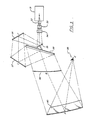
- FIG. 1 is a side view in elevation, partly in perspective, of certain optical display components for the purpose of aiding the explanation of the principles of the invention.
- FIG. 2 is an illustration of the prior art.
- FIG. 3 is a view, like FIG. 1, of a presently preferred embodiment of the invention.
- Referring now to FIG. 1 of the drawings, the
numeral 10 identifies a position in which a trainee with his eyepoint at E in a simulator would view a scene, the center of which is indicated at point A along the line AE. The scene being viewed is a collimated visual image for viewing by at least one trainee, and the center of this scene, point A, is reflected from a spherical mirror 11. The spherical mirror 11 is arranged and positioned so that its reflective surface is on the concave part of its contour. - Actually, the point A is a reflection of a point B, which is the center of a scene formed on a toroidal rear-
projection screen 12. The spherical mirror 11 collimates the scene on thescreen 12. - As the following description unfolds, it will become obvious how the invention in its present embodiment is able to provide to a trainee in a simulator an image of an area of interest which image is substantially undistorted and undiminished in its illumination, i.e., with maximum brightness.
- First, a decision is made as to the area to be displayed during training, and a flight is made in an actual aircraft over that area with a motion picture camera attached to the aircraft pointed at the area of interest. The processed film then is used as an image source for the invention.
- The trainee sits in a simulated aircraft cockpit, which is an exact duplicate of that of the real aircraft, and in this position, he must "fly" in a simulated path, which approximates the actual path followed by the aircraft from which the motion picture was taken. Arranged around the windows of his simulated cockpit is the visual display, which is projected realistically by television monitors.
- The remainder of the system to be described herein, which may be at a remote location to the cockpit position, operates upon the film image to give it the proper perspective from the trainee's viewpoint in the simulator and to position it properly in his field of view. This is done by viewing the image as it is projected by a television camera using well known optical and electronic techniques. A visual display arrangement in accordance with the present invention permits an adjustment to the display which has not been attainable heretofore.
- Referring back again to FIG. 1 of the drawings, the
numeral 12 identifies a rear-projection screen which is positioned substantially at the focal point of a concave spherical mirror 11, at about 1/2 of its radius of curvature. Thescreen 12 is toroidal in configuration and is positioned with its major axis CL-1 substantially horizontal. As viewed in FIG. 1 of the drawings, the major axis CL-1 is perpendicular to the page. Also thescreen 12 is positioned so that it is concave in the same direction as the spherical mirror 11. - A
folding mirror 13 is cylindrical in configuration, with its major axis CL-2 approximately vertical (relative to the major axis of thetoroidal screen 12 and as viewed along the line BD), and is positioned to reflect an image from aflat folding mirror 14, which image originates in alight valve projector 15. Theprojector 15 preferably is a television image projector. - One of the reasons that a
flat folding mirror 14 must be positioned intermediate theprojector 15 and thecylindrical folding mirror 13 is that the light valve projector, which is used so commonly today in simulator visual systems, cannot be tilted more than approximately 30° from the horizontal. At the image output side of theprojector 15 is theusual projection lens 16. - In accordance with one aspect of the present invention, it is desirable and advisable to have an anamorphic lens system 17, the purpose of which will be explained in greater detail presently. After this anamorphic lens system 17, there is a
collimator 18, also to be explained in greater detail presently. - With no distortion compensation (or correction), the output of the "light valve"
projector 15 is a rectangular format with three to four aspect ratio so that it is really one inch (25.4 mm) wide by three-quarters inch (19.05 mm) high. Such a format would appear distorted at theviewing position 10. - However, such distortions are compensated for, in accordance with the present invention, by the
cylindrical mirror 13. The major axis CL-2 of thecylindrical mirror 13 is vertical, when compared with the horizontally positioned major axis CL-1 of thetoroidal screen 12, and this axis of thecylindrical mirror 13 is tilted so that its reflective surface is more nearly perpendicular to the line GD from the flat, foldingmirror 14. The particular degree of tilt would be dependent upon it being sufficient to reflect the format from the flat, foldingmirror 14 onto thetoroidal screen 12 and is a matter of design. - The distortion for which the present invention is so uniquely adapted to compensate is developed because the center line for the curvature of the spherical mirror 11 appears on the dashed
line 19, whereas the viewing axis for this same spherical mirror 11 is the line EAB. The center of curvature for the spherical mirror 11 is on theline 19 as indicated by thereference numeral 20 and not on the line AE or on the line AB. - The center of curvature for the
toroidal screen 12 appears below the line BD at apoint 25. The "viewing system", therefore, is composed of thetoroidal screen 12 and the decentered spherical mirror 11. - The use of the
cylindrical folding mirror 13, therefore, introduces a distortion that compensates for distortions caused by the spherical mirror 11 and thetoroidal screen 12. The spherical mirror 11, is used as a collimator, so that the image appears substantially at infinity for the trainee at theviewing position 10. - The "projection axis" is the line BDGF, whereas the "viewing axis" is the line EAB.
- With the center of
curvature 20 for the spherical mirror 11 being displaced and removed from the line AB a requirement for collimation and field of view in this system can be satisfied. However, also it introduces a distortion such that the lateral edges of the field of view at thescreen 12 appear to droop downwardly. - Under usual circumstances, the illumination is maximized when the viewing axis AB is in alignment with the projection axis BD. Therefore, the nearer that these two axes are in alignment, the better the chances are of achieving maximum illumination.
- Referring now to FIG. 2 of the drawings, a
television camera 21 projects an image directly upon arear projection screen 22 from which the image is reflected from acurved mirror 23 to the viewing position indicated by the letter E'. In accordance with the prior illustration therefore, E' is in proper position to view at A' the reflected point B' which is on thescreen 22. If an undistorted image from theprojector 21 is projected onto thescreen 22, it must satisfy the distortion requirements of the viewing position E', and in so doing, a very large angle a is developed between the viewing system and the projection system. - Such a large angle a develops a non-uniform illumination of the system that is seen by the trainee at the position E'. This uneven and non-uniform illumination will develop in the scene as being darker at the bottom and getting brighter toward the top. This prior art compenates for the non-uniform illumination by introducing
prisms 24 to redirect the light. - A further distinction of the prior art from the present invention is that the
mirror 23 is a spheroid, or an ellipsoid of revolution, resembling a sphere. Now, by utilizing aspherical screen 22, the prior art system then requires that thetelevision projector 21 must be substantially square with thescreen 22 in order to minimize distortion. Nevertheless, the large angle a still requires that some artificial means be employed to improve the illumination. - Contrasting this prior art arrangement with that of the present invention, a toroidal screen and a spherical mirror give a different distortion characteristic to the image produced, i.e., the two outside edges droop downwardly. The distortion that is compensated for by the present invention is that created by the geometrical relationship between the eyepoint E, in FIG. 1, the mirror 11 and the
screen 12. The geometrical relationship between these elements introduces a distortion into this optical system which is substantially compensated for by the positioning of thecylindrical mirror 13 as described, without having to modify theprojector 15 and without additional optical components. - In a majority of the instances, the
cylindrical mirror 13 will be sufficient to compensate for all of the obvious and detectable distortions. However, in some instances, a further compensation may be indicated. In such an instance, an anamorphoser 17 would compensate for magnification. The anamorphoser 17, accordingly, permits adjustment in one dimension only, such as horizontal, and is used where the height of the image at the screen is correct. - In one actual construction in accordance with the arrangement of FIG. 1, the radius for the spherical mirror 11 is 162 inches (4114.8 mm), the radius for the
screen 12 is 100 inches (2540 mm) and the radius for thecylindrical mirror 13 is 200 inches (5080 mm). The line BD is 34 inches (863.6 mm) in length. - Referring now to FIG. 3 of the drawings the eyepoint E is identified also by the
reference numeral 30. Astandard television projector 31 is positioned to project images through itsnormal lens 32, through ananamorphic lens 33 and acollimator 34 onto afolding mirror 35, whose centerpoint is indicated by the letter G. From themirror 35 the image is folded upwardly to anotherflat folding mirror 36, to a thirdflat folding mirror 37 before it is directed onto acylindrical mirror surface 38. - From the
cylindrical mirror 38 the image is focused onto a rear-projection,curved screen 39, which curvature, preferably is toroidal in configuration. Accordingly, the "projection axis" is the line BDCFG. - From the
toroidal screen 39, the image is reflected from aspherical mirror 40 onto the viewing position at the eyepoint E, in order to form a collimated image. Accordingly, the viewing axis is the line EAB. - In another actual construction in accordance with the arrangement of FIG. 3, the radius for the
spherical mirror 40 again is 162 inches (4114.8 mm), the radius for thescreen 39 again is 100 inches (2540 mm) and the radius for thecylindrical mirror 38 is 300 inches (7620 mm). The line BD is 44 inches (1117.6 mm) in length. - While the essential characteristic of the screen and the folding mirror is that they are curved, the particular configuration selected is determined usually by economic considerations, some configurations being quite expensive to manufacture. The cylindrical configuration is most often the least expensive, but without the method of positioning of a toroidal screen and folding cylindrical mirror as taught by the present invention, the effectiveness of any selected configuration could not be realized.
Claims (13)
Applications Claiming Priority (2)
| Application Number | Priority Date | Filing Date | Title |
|---|---|---|---|
| US06/062,446 US4234891A (en) | 1979-07-30 | 1979-07-30 | Optical illumination and distortion compensator |
| US62446 | 1979-07-30 |
Publications (3)
| Publication Number | Publication Date |
|---|---|
| EP0032499A1 EP0032499A1 (en) | 1981-07-29 |
| EP0032499A4 EP0032499A4 (en) | 1981-12-10 |
| EP0032499B1 true EP0032499B1 (en) | 1985-07-03 |
Family
ID=22042541
Family Applications (1)
| Application Number | Title | Priority Date | Filing Date |
|---|---|---|---|
| EP80901517A Expired EP0032499B1 (en) | 1979-07-30 | 1980-07-03 | Optical illumination and distortion compensator |
Country Status (6)
| Country | Link |
|---|---|
| US (1) | US4234891A (en) |
| EP (1) | EP0032499B1 (en) |
| JP (1) | JPS56500942A (en) |
| CA (1) | CA1119852A (en) |
| DE (1) | DE3070828D1 (en) |
| WO (1) | WO1981000499A1 (en) |
Families Citing this family (29)
| Publication number | Priority date | Publication date | Assignee | Title |
|---|---|---|---|---|
| US4427274A (en) | 1981-04-15 | 1984-01-24 | Mcdonnell Douglas Corporation | Wide angle projection system |
| US4773748A (en) * | 1984-10-09 | 1988-09-27 | Hughes Aircraft Company | Dynamically controlled mirror for reduction of projected image distortion |
| FR2607269B1 (en) * | 1986-11-21 | 1989-03-24 | Trt Telecom Radio Electr | DISTORTION CATCH-UP DEVICE |
| FR2622307B1 (en) * | 1987-10-27 | 1990-03-09 | Trt Telecom Radio Electr | DEVICE FOR RETRIEVING THE TOTAL DISTORTION GENERATED BY THE FORM OF A TRANSPARENT WALL |
| FR2662838B1 (en) * | 1990-06-01 | 1994-05-06 | Thomson Csf | WIDE ANGLE DISPLAY DEVICE FOR LOW - SIZE SIMULATOR. |
| GB9410254D0 (en) * | 1994-05-23 | 1994-07-13 | Virtual Control Limited | Generating an image |
| US5584696A (en) * | 1994-07-28 | 1996-12-17 | Evans & Sutherland Computer Corp. | Hang gliding simulation system with a stereoscopic display and method of simulating hang gliding |
| US6224218B1 (en) * | 1996-05-31 | 2001-05-01 | L-3 Communications Corporation | Backscreen edge contouring for off-axis large field of view displays |
| DE29722785U1 (en) * | 1997-12-23 | 1998-02-12 | Gerzen, Peter, 91580 Petersaurach | Image projection device |
| DE29716798U1 (en) * | 1997-09-18 | 1997-11-27 | Gerzen, Peter, 91580 Petersaurach | Image projection device |
| US6191759B1 (en) * | 1997-12-02 | 2001-02-20 | Gregory J. Kintz | Virtual reality system with a static light emitting surface and magnifying optical system |
| US6118414A (en) * | 1997-12-02 | 2000-09-12 | Kintz; Gregory J. | Virtual reality system and method |
| US5890788A (en) * | 1997-12-10 | 1999-04-06 | Raytheon Company | Anamophic optical system |
| GB0014672D0 (en) * | 2000-06-15 | 2000-08-09 | Seos Displays Ltd | Improved visual display apparatus |
| US20030048391A1 (en) * | 2001-09-07 | 2003-03-13 | Myers Kenneth J. | Projection television having an improved mirror system |
| CN101617354A (en) | 2006-12-12 | 2009-12-30 | 埃文斯和萨瑟兰计算机公司 | Be used for calibrating the system and method for the rgb light of single modulator projector |
| US20080259988A1 (en) * | 2007-01-19 | 2008-10-23 | Evans & Sutherland Computer Corporation | Optical actuator with improved response time and method of making the same |
| WO2009033122A1 (en) * | 2007-09-07 | 2009-03-12 | Evans & Sutherland Computer Corporation | Device and method for reducing etendue in a diode laser |
| US8358317B2 (en) | 2008-05-23 | 2013-01-22 | Evans & Sutherland Computer Corporation | System and method for displaying a planar image on a curved surface |
| US8702248B1 (en) | 2008-06-11 | 2014-04-22 | Evans & Sutherland Computer Corporation | Projection method for reducing interpixel gaps on a viewing surface |
| US8077378B1 (en) | 2008-11-12 | 2011-12-13 | Evans & Sutherland Computer Corporation | Calibration system and method for light modulation device |
| JP2011242580A (en) * | 2010-05-18 | 2011-12-01 | Olympus Corp | Projection optical device |
| US9641826B1 (en) | 2011-10-06 | 2017-05-02 | Evans & Sutherland Computer Corporation | System and method for displaying distant 3-D stereo on a dome surface |
| GB2496534B (en) * | 2013-01-14 | 2013-10-09 | Stromberg Ind Aps | Rear screen projection apparatus and method |
| TW201819990A (en) * | 2016-10-31 | 2018-06-01 | 美商康寧公司 | Monocentric wide field personal display |
| EP3599495A1 (en) * | 2018-07-24 | 2020-01-29 | ScioTeq BVBA | Collimated visual display system |
| US11122243B2 (en) | 2018-11-19 | 2021-09-14 | Flightsafety International Inc. | Method and apparatus for remapping pixel locations |
| CN113424103B (en) * | 2018-11-20 | 2023-07-18 | 飞行安全国际公司 | Rear Projection Simulator with Freeform Folding Mirror |
| RU2749198C1 (en) * | 2020-12-14 | 2021-06-07 | Владимир Владимирович Большаков | Device for projecting images in a collimation stream (options) |
Family Cites Families (10)
| Publication number | Priority date | Publication date | Assignee | Title |
|---|---|---|---|---|
| US3589796A (en) * | 1966-09-19 | 1971-06-29 | United Aircraft Corp | Collimated viewing system |
| GB1297139A (en) * | 1969-07-03 | 1972-11-22 | ||
| US3807849A (en) * | 1970-05-15 | 1974-04-30 | Redifon Ltd | Visual display arrangements |
| GB1385908A (en) * | 1971-05-12 | 1975-03-05 | Redifon Ltd | Visual display apparatus |
| US3785715A (en) * | 1972-05-17 | 1974-01-15 | Singer Co | Panoramic infinity image display |
| US3774990A (en) * | 1972-09-29 | 1973-11-27 | J Beck | Visual simulation optical system |
| US3895861A (en) * | 1974-09-13 | 1975-07-22 | Us Navy | Rear-screen wide-angle on-axis projection system |
| US3988059A (en) * | 1975-06-23 | 1976-10-26 | Sanders Associates, Inc. | Projector |
| US4112462A (en) * | 1976-11-26 | 1978-09-05 | The Singer Company | Infinity image display having increased vertical field of view |
| US4129365A (en) * | 1977-05-13 | 1978-12-12 | Sperry Rand Corporation | Wide angle anamorphic display projection system |
-
1979
- 1979-07-30 US US06/062,446 patent/US4234891A/en not_active Expired - Lifetime
-
1980
- 1980-07-03 EP EP80901517A patent/EP0032499B1/en not_active Expired
- 1980-07-03 WO PCT/US1980/000850 patent/WO1981000499A1/en not_active Ceased
- 1980-07-03 DE DE8080901517T patent/DE3070828D1/en not_active Expired
- 1980-07-03 JP JP50183080A patent/JPS56500942A/ja active Pending
- 1980-07-14 CA CA000356100A patent/CA1119852A/en not_active Expired
Also Published As
| Publication number | Publication date |
|---|---|
| CA1119852A (en) | 1982-03-16 |
| WO1981000499A1 (en) | 1981-02-19 |
| US4234891A (en) | 1980-11-18 |
| JPS56500942A (en) | 1981-07-09 |
| EP0032499A1 (en) | 1981-07-29 |
| DE3070828D1 (en) | 1985-08-08 |
| EP0032499A4 (en) | 1981-12-10 |
Similar Documents
| Publication | Publication Date | Title |
|---|---|---|
| US4234891A (en) | Optical illumination and distortion compensator | |
| US3784742A (en) | Ground-based flight simulating apparatus | |
| US3785715A (en) | Panoramic infinity image display | |
| US6176584B1 (en) | Curved surface, real image dome display system, using laser-based rear projection | |
| US5189452A (en) | Real image projection system | |
| US5071209A (en) | Variable acuity non-linear projection system | |
| US5582518A (en) | System for restoring the visual environment of a pilot in a simulator | |
| US6814578B2 (en) | Visual display system and method for displaying images utilizing a holographic collimator | |
| US4093347A (en) | Optical simulation apparatus using controllable real-life element | |
| US3514871A (en) | Wide angle visual display | |
| US8587497B2 (en) | Method and apparatus for a wide field of view display | |
| EP0875055B1 (en) | An image projection display system for use in large field-of-view presentation | |
| US5253116A (en) | Collimated viewing device with off-axis spherical mirror for simulator | |
| US3895861A (en) | Rear-screen wide-angle on-axis projection system | |
| US3932702A (en) | Optical system for the display of visual images | |
| US3557470A (en) | Simulator having visually independent display system | |
| US3551043A (en) | Virtual image window display | |
| US6552699B2 (en) | Multiple target projector system and method | |
| US4395234A (en) | Optical scanning probe with multiple outputs | |
| GB2091193A (en) | Simulator for simulating, for example, aircraft flight | |
| US4112462A (en) | Infinity image display having increased vertical field of view | |
| EP0766860B1 (en) | Generating an image | |
| GB2349236A (en) | Projection systems | |
| GB2317297A (en) | An image projection system for use in large field of view presentation | |
| US3371432A (en) | Visual simulation |
Legal Events
| Date | Code | Title | Description |
|---|---|---|---|
| PUAI | Public reference made under article 153(3) epc to a published international application that has entered the european phase |
Free format text: ORIGINAL CODE: 0009012 |
|
| AK | Designated contracting states |
Designated state(s): DE FR GB |
|
| 17P | Request for examination filed |
Effective date: 19810807 |
|
| GRAA | (expected) grant |
Free format text: ORIGINAL CODE: 0009210 |
|
| AK | Designated contracting states |
Designated state(s): DE FR GB |
|
| REF | Corresponds to: |
Ref document number: 3070828 Country of ref document: DE Date of ref document: 19850808 |
|
| ET | Fr: translation filed | ||
| PLBE | No opposition filed within time limit |
Free format text: ORIGINAL CODE: 0009261 |
|
| STAA | Information on the status of an ep patent application or granted ep patent |
Free format text: STATUS: NO OPPOSITION FILED WITHIN TIME LIMIT |
|
| 26N | No opposition filed | ||
| PG25 | Lapsed in a contracting state [announced via postgrant information from national office to epo] |
Ref country code: FR Free format text: LAPSE BECAUSE OF NON-PAYMENT OF DUE FEES Effective date: 19880331 |
|
| PG25 | Lapsed in a contracting state [announced via postgrant information from national office to epo] |
Ref country code: DE Effective date: 19880401 |
|
| REG | Reference to a national code |
Ref country code: FR Ref legal event code: ST |
|
| PGFP | Annual fee paid to national office [announced via postgrant information from national office to epo] |
Ref country code: GB Payment date: 19920626 Year of fee payment: 13 |
|
| PG25 | Lapsed in a contracting state [announced via postgrant information from national office to epo] |
Ref country code: GB Effective date: 19930703 |
|
| GBPC | Gb: european patent ceased through non-payment of renewal fee |
Effective date: 19930703 |