EP0031724A2 - Reinforced membranes, process and apparatus for making them, and use thereof as ion-exchange membranes in chlor-alkali cells or as catalysts - Google Patents
Reinforced membranes, process and apparatus for making them, and use thereof as ion-exchange membranes in chlor-alkali cells or as catalysts Download PDFInfo
- Publication number
- EP0031724A2 EP0031724A2 EP80304717A EP80304717A EP0031724A2 EP 0031724 A2 EP0031724 A2 EP 0031724A2 EP 80304717 A EP80304717 A EP 80304717A EP 80304717 A EP80304717 A EP 80304717A EP 0031724 A2 EP0031724 A2 EP 0031724A2
- Authority
- EP
- European Patent Office
- Prior art keywords
- membrane
- films
- fluorinated polymer
- polymer
- reinforced
- Prior art date
- Legal status (The legal status is an assumption and is not a legal conclusion. Google has not performed a legal analysis and makes no representation as to the accuracy of the status listed.)
- Granted
Links
- 239000012528 membrane Substances 0.000 title claims abstract description 130
- 238000000034 method Methods 0.000 title claims description 40
- 230000008569 process Effects 0.000 title claims description 29
- 239000003513 alkali Substances 0.000 title claims description 8
- 239000003014 ion exchange membrane Substances 0.000 title claims description 7
- 239000003054 catalyst Substances 0.000 title claims description 6
- 229920002313 fluoropolymer Polymers 0.000 claims abstract description 48
- 239000004744 fabric Substances 0.000 claims abstract description 37
- 239000012779 reinforcing material Substances 0.000 claims abstract description 37
- 125000000472 sulfonyl group Chemical group *S(*)(=O)=O 0.000 claims abstract description 27
- 230000003014 reinforcing effect Effects 0.000 claims abstract description 24
- 125000003178 carboxy group Chemical group [H]OC(*)=O 0.000 claims abstract description 20
- 238000005342 ion exchange Methods 0.000 claims abstract description 17
- 238000001816 cooling Methods 0.000 claims abstract description 3
- 229920000642 polymer Polymers 0.000 claims description 70
- 125000000524 functional group Chemical group 0.000 claims description 25
- 239000000463 material Substances 0.000 claims description 19
- 238000010438 heat treatment Methods 0.000 claims description 9
- 238000005868 electrolysis reaction Methods 0.000 claims description 7
- 125000000542 sulfonic acid group Chemical group 0.000 claims description 4
- 230000003247 decreasing effect Effects 0.000 claims description 2
- 239000000178 monomer Substances 0.000 description 30
- 229920001577 copolymer Polymers 0.000 description 27
- 230000007062 hydrolysis Effects 0.000 description 22
- 238000006460 hydrolysis reaction Methods 0.000 description 22
- 239000010410 layer Substances 0.000 description 16
- -1 perfluoroalkyl radical Chemical class 0.000 description 16
- BFKJFAAPBSQJPD-UHFFFAOYSA-N tetrafluoroethene Chemical group FC(F)=C(F)F BFKJFAAPBSQJPD-UHFFFAOYSA-N 0.000 description 15
- 239000000460 chlorine Substances 0.000 description 10
- HEMHJVSKTPXQMS-UHFFFAOYSA-M Sodium hydroxide Chemical compound [OH-].[Na+] HEMHJVSKTPXQMS-UHFFFAOYSA-M 0.000 description 9
- 229910052801 chlorine Inorganic materials 0.000 description 9
- 238000003475 lamination Methods 0.000 description 9
- 238000002360 preparation method Methods 0.000 description 9
- 230000002787 reinforcement Effects 0.000 description 9
- TUFKHKZLBZWCAW-UHFFFAOYSA-N 2-(1-ethenoxypropan-2-yloxy)ethanesulfonyl fluoride Chemical compound C=COCC(C)OCCS(F)(=O)=O TUFKHKZLBZWCAW-UHFFFAOYSA-N 0.000 description 8
- 239000000203 mixture Substances 0.000 description 8
- 229920006254 polymer film Polymers 0.000 description 8
- 238000007789 sealing Methods 0.000 description 8
- 125000000217 alkyl group Chemical group 0.000 description 7
- 239000012267 brine Substances 0.000 description 7
- 238000006243 chemical reaction Methods 0.000 description 7
- 235000019000 fluorine Nutrition 0.000 description 7
- HPALAKNZSZLMCH-UHFFFAOYSA-M sodium;chloride;hydrate Chemical compound O.[Na+].[Cl-] HPALAKNZSZLMCH-UHFFFAOYSA-M 0.000 description 7
- 239000000243 solution Substances 0.000 description 7
- ZAMOUSCENKQFHK-UHFFFAOYSA-N Chlorine atom Chemical compound [Cl] ZAMOUSCENKQFHK-UHFFFAOYSA-N 0.000 description 6
- 229910052731 fluorine Inorganic materials 0.000 description 6
- 125000001153 fluoro group Chemical group F* 0.000 description 6
- 239000001257 hydrogen Substances 0.000 description 6
- 229910052739 hydrogen Inorganic materials 0.000 description 6
- QSHDDOUJBYECFT-UHFFFAOYSA-N mercury Chemical compound [Hg] QSHDDOUJBYECFT-UHFFFAOYSA-N 0.000 description 6
- 229910052753 mercury Inorganic materials 0.000 description 6
- OBTWBSRJZRCYQV-UHFFFAOYSA-N sulfuryl difluoride Chemical compound FS(F)(=O)=O OBTWBSRJZRCYQV-UHFFFAOYSA-N 0.000 description 6
- 238000010030 laminating Methods 0.000 description 5
- 229910052751 metal Inorganic materials 0.000 description 5
- 239000002184 metal Substances 0.000 description 5
- 238000006116 polymerization reaction Methods 0.000 description 5
- 125000000391 vinyl group Chemical group [H]C([*])=C([H])[H] 0.000 description 5
- OKTJSMMVPCPJKN-UHFFFAOYSA-N Carbon Chemical compound [C] OKTJSMMVPCPJKN-UHFFFAOYSA-N 0.000 description 4
- RTZKZFJDLAIYFH-UHFFFAOYSA-N Diethyl ether Chemical compound CCOCC RTZKZFJDLAIYFH-UHFFFAOYSA-N 0.000 description 4
- IAZDPXIOMUYVGZ-UHFFFAOYSA-N Dimethylsulphoxide Chemical compound CS(C)=O IAZDPXIOMUYVGZ-UHFFFAOYSA-N 0.000 description 4
- PIICEJLVQHRZGT-UHFFFAOYSA-N Ethylenediamine Chemical compound NCCN PIICEJLVQHRZGT-UHFFFAOYSA-N 0.000 description 4
- UFHFLCQGNIYNRP-UHFFFAOYSA-N Hydrogen Chemical compound [H][H] UFHFLCQGNIYNRP-UHFFFAOYSA-N 0.000 description 4
- 239000002253 acid Substances 0.000 description 4
- 229910052783 alkali metal Inorganic materials 0.000 description 4
- 239000002585 base Substances 0.000 description 4
- 230000008901 benefit Effects 0.000 description 4
- 230000015572 biosynthetic process Effects 0.000 description 4
- 239000007789 gas Substances 0.000 description 4
- 150000003839 salts Chemical class 0.000 description 4
- UHOVQNZJYSORNB-UHFFFAOYSA-N Benzene Chemical compound C1=CC=CC=C1 UHOVQNZJYSORNB-UHFFFAOYSA-N 0.000 description 3
- OKKJLVBELUTLKV-UHFFFAOYSA-N Methanol Chemical compound OC OKKJLVBELUTLKV-UHFFFAOYSA-N 0.000 description 3
- 229910006095 SO2F Inorganic materials 0.000 description 3
- RTAQQCXQSZGOHL-UHFFFAOYSA-N Titanium Chemical compound [Ti] RTAQQCXQSZGOHL-UHFFFAOYSA-N 0.000 description 3
- 229910052799 carbon Inorganic materials 0.000 description 3
- 125000002843 carboxylic acid group Chemical group 0.000 description 3
- 150000001875 compounds Chemical class 0.000 description 3
- 238000010276 construction Methods 0.000 description 3
- 230000000694 effects Effects 0.000 description 3
- 230000008030 elimination Effects 0.000 description 3
- 238000003379 elimination reaction Methods 0.000 description 3
- 238000005538 encapsulation Methods 0.000 description 3
- 239000011737 fluorine Substances 0.000 description 3
- 239000010439 graphite Substances 0.000 description 3
- 229910002804 graphite Inorganic materials 0.000 description 3
- 150000002430 hydrocarbons Chemical group 0.000 description 3
- 239000003999 initiator Substances 0.000 description 3
- 230000020477 pH reduction Effects 0.000 description 3
- 150000003254 radicals Chemical class 0.000 description 3
- 239000002344 surface layer Substances 0.000 description 3
- 239000010936 titanium Substances 0.000 description 3
- 229910052719 titanium Inorganic materials 0.000 description 3
- 239000002759 woven fabric Substances 0.000 description 3
- VHUUQVKOLVNVRT-UHFFFAOYSA-N Ammonium hydroxide Chemical compound [NH4+].[OH-] VHUUQVKOLVNVRT-UHFFFAOYSA-N 0.000 description 2
- LSNNMFCWUKXFEE-UHFFFAOYSA-M Bisulfite Chemical compound OS([O-])=O LSNNMFCWUKXFEE-UHFFFAOYSA-M 0.000 description 2
- OYPRJOBELJOOCE-UHFFFAOYSA-N Calcium Chemical compound [Ca] OYPRJOBELJOOCE-UHFFFAOYSA-N 0.000 description 2
- VGGSQFUCUMXWEO-UHFFFAOYSA-N Ethene Chemical class C=C VGGSQFUCUMXWEO-UHFFFAOYSA-N 0.000 description 2
- YNQLUTRBYVCPMQ-UHFFFAOYSA-N Ethylbenzene Chemical compound CCC1=CC=CC=C1 YNQLUTRBYVCPMQ-UHFFFAOYSA-N 0.000 description 2
- OAKJQQAXSVQMHS-UHFFFAOYSA-N Hydrazine Chemical compound NN OAKJQQAXSVQMHS-UHFFFAOYSA-N 0.000 description 2
- FAPWRFPIFSIZLT-UHFFFAOYSA-M Sodium chloride Chemical compound [Na+].[Cl-] FAPWRFPIFSIZLT-UHFFFAOYSA-M 0.000 description 2
- 238000005299 abrasion Methods 0.000 description 2
- 150000008044 alkali metal hydroxides Chemical class 0.000 description 2
- 150000001340 alkali metals Chemical group 0.000 description 2
- 229910052784 alkaline earth metal Inorganic materials 0.000 description 2
- 229910001860 alkaline earth metal hydroxide Inorganic materials 0.000 description 2
- 150000001412 amines Chemical class 0.000 description 2
- 239000000908 ammonium hydroxide Substances 0.000 description 2
- 239000012736 aqueous medium Substances 0.000 description 2
- 230000004888 barrier function Effects 0.000 description 2
- HQABUPZFAYXKJW-UHFFFAOYSA-N butan-1-amine Chemical compound CCCCN HQABUPZFAYXKJW-UHFFFAOYSA-N 0.000 description 2
- 229910052791 calcium Inorganic materials 0.000 description 2
- 239000011575 calcium Substances 0.000 description 2
- 125000004432 carbon atom Chemical group C* 0.000 description 2
- 239000003518 caustics Substances 0.000 description 2
- 238000005520 cutting process Methods 0.000 description 2
- 229920001971 elastomer Polymers 0.000 description 2
- 230000032050 esterification Effects 0.000 description 2
- 238000005886 esterification reaction Methods 0.000 description 2
- 239000000835 fiber Substances 0.000 description 2
- ZQBFAOFFOQMSGJ-UHFFFAOYSA-N hexafluorobenzene Chemical compound FC1=C(F)C(F)=C(F)C(F)=C1F ZQBFAOFFOQMSGJ-UHFFFAOYSA-N 0.000 description 2
- HCDGVLDPFQMKDK-UHFFFAOYSA-N hexafluoropropylene Chemical group FC(F)=C(F)C(F)(F)F HCDGVLDPFQMKDK-UHFFFAOYSA-N 0.000 description 2
- 150000002431 hydrogen Chemical class 0.000 description 2
- XLYOFNOQVPJJNP-UHFFFAOYSA-M hydroxide Chemical compound [OH-] XLYOFNOQVPJJNP-UHFFFAOYSA-M 0.000 description 2
- 238000002955 isolation Methods 0.000 description 2
- 239000007788 liquid Substances 0.000 description 2
- 230000003647 oxidation Effects 0.000 description 2
- 238000007254 oxidation reaction Methods 0.000 description 2
- 239000002245 particle Substances 0.000 description 2
- 229920001343 polytetrafluoroethylene Polymers 0.000 description 2
- 239000004810 polytetrafluoroethylene Substances 0.000 description 2
- 239000002243 precursor Substances 0.000 description 2
- 238000012545 processing Methods 0.000 description 2
- 230000009467 reduction Effects 0.000 description 2
- 238000005096 rolling process Methods 0.000 description 2
- 238000007493 shaping process Methods 0.000 description 2
- 239000007787 solid Substances 0.000 description 2
- 239000002904 solvent Substances 0.000 description 2
- 239000010935 stainless steel Substances 0.000 description 2
- 229910001220 stainless steel Inorganic materials 0.000 description 2
- BUUPQKDIAURBJP-UHFFFAOYSA-N sulfinic acid Chemical compound OS=O BUUPQKDIAURBJP-UHFFFAOYSA-N 0.000 description 2
- 125000000565 sulfonamide group Chemical group 0.000 description 2
- 125000001273 sulfonato group Chemical group [O-]S(*)(=O)=O 0.000 description 2
- TXEYQDLBPFQVAA-UHFFFAOYSA-N tetrafluoromethane Chemical compound FC(F)(F)F TXEYQDLBPFQVAA-UHFFFAOYSA-N 0.000 description 2
- KHXKESCWFMPTFT-UHFFFAOYSA-N 1,1,1,2,2,3,3-heptafluoro-3-(1,2,2-trifluoroethenoxy)propane Chemical compound FC(F)=C(F)OC(F)(F)C(F)(F)C(F)(F)F KHXKESCWFMPTFT-UHFFFAOYSA-N 0.000 description 1
- QIROQPWSJUXOJC-UHFFFAOYSA-N 1,1,2,2,3,3,4,4,5,5,6-undecafluoro-6-(trifluoromethyl)cyclohexane Chemical compound FC(F)(F)C1(F)C(F)(F)C(F)(F)C(F)(F)C(F)(F)C1(F)F QIROQPWSJUXOJC-UHFFFAOYSA-N 0.000 description 1
- AJDIZQLSFPQPEY-UHFFFAOYSA-N 1,1,2-Trichlorotrifluoroethane Chemical compound FC(F)(Cl)C(F)(Cl)Cl AJDIZQLSFPQPEY-UHFFFAOYSA-N 0.000 description 1
- MIZLGWKEZAPEFJ-UHFFFAOYSA-N 1,1,2-trifluoroethene Chemical group FC=C(F)F MIZLGWKEZAPEFJ-UHFFFAOYSA-N 0.000 description 1
- BQCIDUSAKPWEOX-UHFFFAOYSA-N 1,1-Difluoroethene Chemical compound FC(F)=C BQCIDUSAKPWEOX-UHFFFAOYSA-N 0.000 description 1
- KXGFMDJXCMQABM-UHFFFAOYSA-N 2-methoxy-6-methylphenol Chemical compound [CH]OC1=CC=CC([CH])=C1O KXGFMDJXCMQABM-UHFFFAOYSA-N 0.000 description 1
- MGWGWNFMUOTEHG-UHFFFAOYSA-N 4-(3,5-dimethylphenyl)-1,3-thiazol-2-amine Chemical compound CC1=CC(C)=CC(C=2N=C(N)SC=2)=C1 MGWGWNFMUOTEHG-UHFFFAOYSA-N 0.000 description 1
- QGZKDVFQNNGYKY-UHFFFAOYSA-O Ammonium Chemical group [NH4+] QGZKDVFQNNGYKY-UHFFFAOYSA-O 0.000 description 1
- LFQSCWFLJHTTHZ-UHFFFAOYSA-N Ethanol Chemical compound CCO LFQSCWFLJHTTHZ-UHFFFAOYSA-N 0.000 description 1
- 239000005977 Ethylene Substances 0.000 description 1
- PXGOKWXKJXAPGV-UHFFFAOYSA-N Fluorine Chemical compound FF PXGOKWXKJXAPGV-UHFFFAOYSA-N 0.000 description 1
- 239000004698 Polyethylene Substances 0.000 description 1
- 239000004743 Polypropylene Substances 0.000 description 1
- LSNNMFCWUKXFEE-UHFFFAOYSA-N Sulfurous acid Chemical class OS(O)=O LSNNMFCWUKXFEE-UHFFFAOYSA-N 0.000 description 1
- HCHKCACWOHOZIP-UHFFFAOYSA-N Zinc Chemical compound [Zn] HCHKCACWOHOZIP-UHFFFAOYSA-N 0.000 description 1
- 238000010521 absorption reaction Methods 0.000 description 1
- 150000007513 acids Chemical class 0.000 description 1
- 150000001342 alkaline earth metals Chemical group 0.000 description 1
- 230000029936 alkylation Effects 0.000 description 1
- 238000005804 alkylation reaction Methods 0.000 description 1
- 239000000956 alloy Substances 0.000 description 1
- 229910045601 alloy Inorganic materials 0.000 description 1
- 229910052782 aluminium Inorganic materials 0.000 description 1
- XAGFODPZIPBFFR-UHFFFAOYSA-N aluminium Chemical compound [Al] XAGFODPZIPBFFR-UHFFFAOYSA-N 0.000 description 1
- 239000007864 aqueous solution Substances 0.000 description 1
- 150000001491 aromatic compounds Chemical class 0.000 description 1
- 125000003118 aryl group Chemical group 0.000 description 1
- QVGXLLKOCUKJST-UHFFFAOYSA-N atomic oxygen Chemical compound [O] QVGXLLKOCUKJST-UHFFFAOYSA-N 0.000 description 1
- 230000001588 bifunctional effect Effects 0.000 description 1
- 238000009835 boiling Methods 0.000 description 1
- 238000005341 cation exchange Methods 0.000 description 1
- 125000002091 cationic group Chemical group 0.000 description 1
- 150000001768 cations Chemical class 0.000 description 1
- 239000004568 cement Substances 0.000 description 1
- 238000003843 chloralkali process Methods 0.000 description 1
- UUAGAQFQZIEFAH-UHFFFAOYSA-N chlorotrifluoroethylene Chemical group FC(F)=C(F)Cl UUAGAQFQZIEFAH-UHFFFAOYSA-N 0.000 description 1
- KRVSOGSZCMJSLX-UHFFFAOYSA-L chromic acid Substances O[Cr](O)(=O)=O KRVSOGSZCMJSLX-UHFFFAOYSA-L 0.000 description 1
- 230000001112 coagulating effect Effects 0.000 description 1
- 238000001246 colloidal dispersion Methods 0.000 description 1
- 238000007334 copolymerization reaction Methods 0.000 description 1
- 238000006298 dechlorination reaction Methods 0.000 description 1
- 230000007812 deficiency Effects 0.000 description 1
- 230000008021 deposition Effects 0.000 description 1
- 239000002270 dispersing agent Substances 0.000 description 1
- 239000006185 dispersion Substances 0.000 description 1
- 229910001651 emery Inorganic materials 0.000 description 1
- 125000000816 ethylene group Chemical group [H]C([H])([*:1])C([H])([H])[*:2] 0.000 description 1
- 239000011152 fibreglass Substances 0.000 description 1
- XUCNUKMRBVNAPB-UHFFFAOYSA-N fluoroethene Chemical compound FC=C XUCNUKMRBVNAPB-UHFFFAOYSA-N 0.000 description 1
- AWJWCTOOIBYHON-UHFFFAOYSA-N furo[3,4-b]pyrazine-5,7-dione Chemical compound C1=CN=C2C(=O)OC(=O)C2=N1 AWJWCTOOIBYHON-UHFFFAOYSA-N 0.000 description 1
- 239000011521 glass Substances 0.000 description 1
- 229930195733 hydrocarbon Natural products 0.000 description 1
- 230000003301 hydrolyzing effect Effects 0.000 description 1
- GPRLSGONYQIRFK-UHFFFAOYSA-N hydron Chemical compound [H+] GPRLSGONYQIRFK-UHFFFAOYSA-N 0.000 description 1
- 230000001771 impaired effect Effects 0.000 description 1
- 230000006872 improvement Effects 0.000 description 1
- 239000012535 impurity Substances 0.000 description 1
- 229910052500 inorganic mineral Inorganic materials 0.000 description 1
- 238000003780 insertion Methods 0.000 description 1
- 230000037431 insertion Effects 0.000 description 1
- 238000004519 manufacturing process Methods 0.000 description 1
- 239000000155 melt Substances 0.000 description 1
- 229910000000 metal hydroxide Inorganic materials 0.000 description 1
- 150000004692 metal hydroxides Chemical class 0.000 description 1
- 150000002739 metals Chemical class 0.000 description 1
- 238000013508 migration Methods 0.000 description 1
- 239000011707 mineral Substances 0.000 description 1
- 235000010755 mineral Nutrition 0.000 description 1
- 239000002808 molecular sieve Substances 0.000 description 1
- 125000002560 nitrile group Chemical group 0.000 description 1
- JCXJVPUVTGWSNB-UHFFFAOYSA-N nitrogen dioxide Inorganic materials O=[N]=O JCXJVPUVTGWSNB-UHFFFAOYSA-N 0.000 description 1
- 239000004745 nonwoven fabric Substances 0.000 description 1
- 150000002894 organic compounds Chemical class 0.000 description 1
- 239000001301 oxygen Substances 0.000 description 1
- 229910052760 oxygen Inorganic materials 0.000 description 1
- 230000035515 penetration Effects 0.000 description 1
- YVBBRRALBYAZBM-UHFFFAOYSA-N perfluorooctane Chemical compound FC(F)(F)C(F)(F)C(F)(F)C(F)(F)C(F)(F)C(F)(F)C(F)(F)C(F)(F)F YVBBRRALBYAZBM-UHFFFAOYSA-N 0.000 description 1
- 150000002978 peroxides Chemical class 0.000 description 1
- 229920001568 phenolic resin Polymers 0.000 description 1
- 239000005011 phenolic resin Substances 0.000 description 1
- 229920000573 polyethylene Polymers 0.000 description 1
- 229920001721 polyimide Polymers 0.000 description 1
- 239000009719 polyimide resin Substances 0.000 description 1
- 229920001155 polypropylene Polymers 0.000 description 1
- 239000010453 quartz Substances 0.000 description 1
- 239000012783 reinforcing fiber Substances 0.000 description 1
- 238000001223 reverse osmosis Methods 0.000 description 1
- 229920006395 saturated elastomer Polymers 0.000 description 1
- 238000009738 saturating Methods 0.000 description 1
- VYPSYNLAJGMNEJ-UHFFFAOYSA-N silicon dioxide Inorganic materials O=[Si]=O VYPSYNLAJGMNEJ-UHFFFAOYSA-N 0.000 description 1
- 229920002379 silicone rubber Polymers 0.000 description 1
- 239000004945 silicone rubber Substances 0.000 description 1
- 239000002002 slurry Substances 0.000 description 1
- URGAHOPLAPQHLN-UHFFFAOYSA-N sodium aluminosilicate Chemical compound [Na+].[Al+3].[O-][Si]([O-])=O.[O-][Si]([O-])=O URGAHOPLAPQHLN-UHFFFAOYSA-N 0.000 description 1
- 239000011780 sodium chloride Substances 0.000 description 1
- 238000010186 staining Methods 0.000 description 1
- 239000000126 substance Substances 0.000 description 1
- YBBRCQOCSYXUOC-UHFFFAOYSA-N sulfuryl dichloride Chemical group ClS(Cl)(=O)=O YBBRCQOCSYXUOC-UHFFFAOYSA-N 0.000 description 1
- 230000003746 surface roughness Effects 0.000 description 1
- 230000008961 swelling Effects 0.000 description 1
- 229920001897 terpolymer Polymers 0.000 description 1
- 238000012360 testing method Methods 0.000 description 1
- 229920002554 vinyl polymer Polymers 0.000 description 1
- ORGHESHFQPYLAO-UHFFFAOYSA-N vinyl radical Chemical compound C=[CH] ORGHESHFQPYLAO-UHFFFAOYSA-N 0.000 description 1
- 238000005406 washing Methods 0.000 description 1
- 229910052727 yttrium Inorganic materials 0.000 description 1
Images


Classifications
-
- B—PERFORMING OPERATIONS; TRANSPORTING
- B01—PHYSICAL OR CHEMICAL PROCESSES OR APPARATUS IN GENERAL
- B01D—SEPARATION
- B01D69/00—Semi-permeable membranes for separation processes or apparatus characterised by their form, structure or properties; Manufacturing processes specially adapted therefor
- B01D69/10—Supported membranes; Membrane supports
- B01D69/107—Organic support material
- B01D69/1071—Woven, non-woven or net mesh
-
- B—PERFORMING OPERATIONS; TRANSPORTING
- B32—LAYERED PRODUCTS
- B32B—LAYERED PRODUCTS, i.e. PRODUCTS BUILT-UP OF STRATA OF FLAT OR NON-FLAT, e.g. CELLULAR OR HONEYCOMB, FORM
- B32B37/00—Methods or apparatus for laminating, e.g. by curing or by ultrasonic bonding
- B32B37/04—Methods or apparatus for laminating, e.g. by curing or by ultrasonic bonding characterised by the partial melting of at least one layer
-
- B—PERFORMING OPERATIONS; TRANSPORTING
- B32—LAYERED PRODUCTS
- B32B—LAYERED PRODUCTS, i.e. PRODUCTS BUILT-UP OF STRATA OF FLAT OR NON-FLAT, e.g. CELLULAR OR HONEYCOMB, FORM
- B32B37/00—Methods or apparatus for laminating, e.g. by curing or by ultrasonic bonding
- B32B37/06—Methods or apparatus for laminating, e.g. by curing or by ultrasonic bonding characterised by the heating method
-
- B—PERFORMING OPERATIONS; TRANSPORTING
- B32—LAYERED PRODUCTS
- B32B—LAYERED PRODUCTS, i.e. PRODUCTS BUILT-UP OF STRATA OF FLAT OR NON-FLAT, e.g. CELLULAR OR HONEYCOMB, FORM
- B32B37/00—Methods or apparatus for laminating, e.g. by curing or by ultrasonic bonding
- B32B37/10—Methods or apparatus for laminating, e.g. by curing or by ultrasonic bonding characterised by the pressing technique, e.g. using action of vacuum or fluid pressure
- B32B37/1027—Pressing using at least one press band
-
- B—PERFORMING OPERATIONS; TRANSPORTING
- B32—LAYERED PRODUCTS
- B32B—LAYERED PRODUCTS, i.e. PRODUCTS BUILT-UP OF STRATA OF FLAT OR NON-FLAT, e.g. CELLULAR OR HONEYCOMB, FORM
- B32B38/00—Ancillary operations in connection with laminating processes
- B32B38/18—Handling of layers or the laminate
- B32B38/1858—Handling of layers or the laminate using vacuum
-
- C—CHEMISTRY; METALLURGY
- C08—ORGANIC MACROMOLECULAR COMPOUNDS; THEIR PREPARATION OR CHEMICAL WORKING-UP; COMPOSITIONS BASED THEREON
- C08J—WORKING-UP; GENERAL PROCESSES OF COMPOUNDING; AFTER-TREATMENT NOT COVERED BY SUBCLASSES C08B, C08C, C08F, C08G or C08H
- C08J5/00—Manufacture of articles or shaped materials containing macromolecular substances
- C08J5/20—Manufacture of shaped structures of ion-exchange resins
- C08J5/22—Films, membranes or diaphragms
- C08J5/2206—Films, membranes or diaphragms based on organic and/or inorganic macromolecular compounds
- C08J5/2218—Synthetic macromolecular compounds
- C08J5/2231—Synthetic macromolecular compounds based on macromolecular compounds obtained by reactions involving unsaturated carbon-to-carbon bonds
- C08J5/2237—Synthetic macromolecular compounds based on macromolecular compounds obtained by reactions involving unsaturated carbon-to-carbon bonds containing fluorine
-
- C—CHEMISTRY; METALLURGY
- C08—ORGANIC MACROMOLECULAR COMPOUNDS; THEIR PREPARATION OR CHEMICAL WORKING-UP; COMPOSITIONS BASED THEREON
- C08J—WORKING-UP; GENERAL PROCESSES OF COMPOUNDING; AFTER-TREATMENT NOT COVERED BY SUBCLASSES C08B, C08C, C08F, C08G or C08H
- C08J5/00—Manufacture of articles or shaped materials containing macromolecular substances
- C08J5/20—Manufacture of shaped structures of ion-exchange resins
- C08J5/22—Films, membranes or diaphragms
- C08J5/2206—Films, membranes or diaphragms based on organic and/or inorganic macromolecular compounds
- C08J5/2275—Heterogeneous membranes
- C08J5/2281—Heterogeneous membranes fluorine containing heterogeneous membranes
-
- C—CHEMISTRY; METALLURGY
- C25—ELECTROLYTIC OR ELECTROPHORETIC PROCESSES; APPARATUS THEREFOR
- C25B—ELECTROLYTIC OR ELECTROPHORETIC PROCESSES FOR THE PRODUCTION OF COMPOUNDS OR NON-METALS; APPARATUS THEREFOR
- C25B13/00—Diaphragms; Spacing elements
-
- B—PERFORMING OPERATIONS; TRANSPORTING
- B29—WORKING OF PLASTICS; WORKING OF SUBSTANCES IN A PLASTIC STATE IN GENERAL
- B29C—SHAPING OR JOINING OF PLASTICS; SHAPING OF MATERIAL IN A PLASTIC STATE, NOT OTHERWISE PROVIDED FOR; AFTER-TREATMENT OF THE SHAPED PRODUCTS, e.g. REPAIRING
- B29C70/00—Shaping composites, i.e. plastics material comprising reinforcements, fillers or preformed parts, e.g. inserts
- B29C70/68—Shaping composites, i.e. plastics material comprising reinforcements, fillers or preformed parts, e.g. inserts by incorporating or moulding on preformed parts, e.g. inserts or layers, e.g. foam blocks
- B29C70/685—Shaping composites, i.e. plastics material comprising reinforcements, fillers or preformed parts, e.g. inserts by incorporating or moulding on preformed parts, e.g. inserts or layers, e.g. foam blocks by laminating inserts between two plastic films or plates
- B29C70/687—Shaping composites, i.e. plastics material comprising reinforcements, fillers or preformed parts, e.g. inserts by incorporating or moulding on preformed parts, e.g. inserts or layers, e.g. foam blocks by laminating inserts between two plastic films or plates the inserts being oriented, e.g. nets or meshes
-
- C—CHEMISTRY; METALLURGY
- C08—ORGANIC MACROMOLECULAR COMPOUNDS; THEIR PREPARATION OR CHEMICAL WORKING-UP; COMPOSITIONS BASED THEREON
- C08J—WORKING-UP; GENERAL PROCESSES OF COMPOUNDING; AFTER-TREATMENT NOT COVERED BY SUBCLASSES C08B, C08C, C08F, C08G or C08H
- C08J2327/00—Characterised by the use of homopolymers or copolymers of compounds having one or more unsaturated aliphatic radicals, each having only one carbon-to-carbon double bond, and at least one being terminated by a halogen; Derivatives of such polymers
- C08J2327/02—Characterised by the use of homopolymers or copolymers of compounds having one or more unsaturated aliphatic radicals, each having only one carbon-to-carbon double bond, and at least one being terminated by a halogen; Derivatives of such polymers not modified by chemical after-treatment
- C08J2327/12—Characterised by the use of homopolymers or copolymers of compounds having one or more unsaturated aliphatic radicals, each having only one carbon-to-carbon double bond, and at least one being terminated by a halogen; Derivatives of such polymers not modified by chemical after-treatment containing fluorine atoms
- C08J2327/18—Homopolymers or copolymers of tetrafluoroethylene
-
- Y—GENERAL TAGGING OF NEW TECHNOLOGICAL DEVELOPMENTS; GENERAL TAGGING OF CROSS-SECTIONAL TECHNOLOGIES SPANNING OVER SEVERAL SECTIONS OF THE IPC; TECHNICAL SUBJECTS COVERED BY FORMER USPC CROSS-REFERENCE ART COLLECTIONS [XRACs] AND DIGESTS
- Y10—TECHNICAL SUBJECTS COVERED BY FORMER USPC
- Y10T—TECHNICAL SUBJECTS COVERED BY FORMER US CLASSIFICATION
- Y10T428/00—Stock material or miscellaneous articles
- Y10T428/24—Structurally defined web or sheet [e.g., overall dimension, etc.]
- Y10T428/24777—Edge feature
Definitions
- the membranes have exceptional uniformity and, in ion-exchange form when used as membranes which separate the compartments of a chloralkali cell, offer the advantages of low operating voltage, low power consumption and high current efficiency, and long useful life without rupture.
- the membrane is a fluorinated cation exchange membrane, one important use of which is to separate the anode and cathode compartments of a chloralkali cell.
- Fluorinated polymers containing pendant side chains containing sulfonyl groups are now well-known, and their use as ion exchange membranes is also known. It is desirable to have an ion exchange membrane which is supported, i.e., which contains a material which imparts physical strength to the fluorinated polymer, so that the physical strength of the complete membrane construction is greater than that of a film of the fluorinated polymer.
- ion exchange membrane which is supported i.e., which contains a material which imparts physical strength to the fluorinated polymer, so that the physical strength of the complete membrane construction is greater than that of a film of the fluorinated polymer.
- Methods for supporting such membranes have not been adequate, for if films of desirable thickness were employed complete encapsulation of the support material was not effected, and if complete encapsulation of the support material were to be assured excessively thick films of fluorinated polymer were required.
- the resulting laminate is then subjected to a second hydrolysis treatment with alkali metal hydroxide, alkaline earth metal hydroxide or ammonium hydroxide after which it is ready for use for ion exchange purposes.
- This method has the disadvantage of adding an additional processing step in the formation of the supported structure, and many additional hours of processing time are required to effect the surface hydrolysis step in the hydroxide treating bath used. Additionally this method cannot be used for fluorinated polymers which contain carboxylic functional groups because the hydrolysis step would lead to carboxylic acid groups or salts thereof, which easily decarboxylate at the temperatures employed in forming the supported construction.
- the sulfonyl and carboxyl groups can be either in melt fabricable form, or, after hydrolysis or other suitable chemical reaction, can be in ion exchange form.
- a reinforced membrane which consists essentially of at least two layers of melt fabricable fluorinated polymer which contains side chains containing sulfonyl and/or carboxyl groups in melt fabricable form, and a woven reinforcing fabric comprising warp and fill strands, there being at least one layer of a said fluorinated polymer on each side of said reinforcing fabric, the warp and fill strands of said reinforcing fabric defining windows between said strands, each layer of fluorinated polymer in at least 70% of the area in each of at least 90% of said windows being of uniform thickness within plus or minus 10%.
- apparatus for making a reinforced membrane comprising,
- Melt fabricable films 11 and 12 of fluorinated polymer containing sulfonyl and/or carboxyl groups, to be described more fully below, and a web of reinforcing material 13, also to be described more fully below, are unwound from supply rolls 14, 1 5 and 16, respectively, in the direction of the arrows shown. Films 11 and 12 and web 13 are brought together over guide roll 17, and further guided through the apparatus around guide rolls 18 and 19.
- Flexible belts 20 and 21 cooperate to contact opposite sides of one edge portion of the assembly of films 11 and 12 and web 13.
- Belts 20 and 21 are suitably made of a thin impervious material such as stainless steel about 5 to 20 mils (0.13 to 0.5 mm) thick. Belts 20 and 21 move in the direction of the arrows shown.
- Belt 20 is guided in a path around rolls 18 and 22.
- Roll 22 is mounted so as to be movable vertically by means of air-actuated cylinders, not shown. In this way roll 22 presses against belt 20 to create a positive tension which prevents the belt from slipping on the rolls it contacts.
- Belt 20 is restrained from wandering laterally along the indicated rolls by use of two guide blocks 23 and 24 within which it passes just before it contacts rolls 18 and 22, respectively.
- Each guide block is fabricated from two members (not separately shown) held together by screws.
- the first member is in the shape of a rectangular solid having machined in one face a shallow depression, about 0.25 mm (10 mils) deep for a belt 0.2 mm (8 mils) thick, and about 1/16 inch (about 1.5 mm) wider than the width of belt 20, and the second member in the form of a rectangular solid is secured by screws to the first member over the machined depression to form a slot through which belt 20 passes.
- the second member of the guide block is placed in position only after endless belt 20 has been positioned in the machined depression.
- Guide blocks 23 and 24 are suitably fabricated from aromatic polyimide resin filled with graphite as is disclosed in U.S. Patent 3,179,631.
- Belt 20 contains a series of perforations along its entire length, not shown in Figure 1, but which will be more fully explained below.
- Belt 21 is guided in a path around rolls 17, 18, 19, 25,: 26 and 27.
- Belt 21 is restrained from a: wandering laterally along those rolls by use of flanges between which belt 21 runs on rolls 26 and 27.
- the shaft of roll 26 is mounted with a screw adjustment for moving roll 26 toward and away from belt 21 to permit increasing or decreasing the tension on belt 21. In this way the tension on belt 21 can be adjusted so that it will not slip.
- a second set of belts not shown in Figure 1 but identical to belts 20 and 21, similarly grips the second edge portion of the assembly of films 11 and 12 and web 13.
- Roll 28 is a resilient rubber roll which is urged by air actuated cylinders toward roll 18 to press belts 20 and 21, films 11 and 12, and web 13 into intimate contact and against roll 18.
- Pipe 30 serves to join vacuum manifold 29 to a vacuum source not shown.
- a similar sealing shoe is used in cooperation with the second set of belts not shown in this view.
- Two banks of heaters (not shown in Figure 1) contained within housings 31 and 32 are positioned on opposite sides of the assembly of films 11 and 12 and web 13.
- the heaters serve to soften films 11 and 12 sufficiently to permit the assembly of films 11 and 12 and web 13 to be fused into a membrane.
- the membrane 33 thus formed is collected on wind-up 34.
- Wind-up 34 and rolls 17 and 13 are driven. They provide the driving force for moving the membrane and assembly of films 11 and 12 and web 13 through the apparatus. The remaining rolls in the apparatus all can be idler rolls.
- Rolls 17 and 18 are suitably covered with a textured surface such as a fine emery cloth. This provides a high enough coefficient of friction of the roll against films 11 and 12 to prevent the films and also belts 20 and 21 from slipping against these driven rolls.
- Figure 1 certain elements in Figure 1 are drawn as not in contact with one another for clarity in showing them, whereas it should be understood that they are in contact during, operation.
- vacuum manifold is shown as not in contact with belt 20, the latter is shown as not in contact with the assembly of webs 11, 12 and 13, the latter is shown as not in contact with belt 21, and the latter is shown as not in contact with sealing shoe 35, whereas during operation these pairs of elements are in fact in contact.
- FIG 2 a partial front view of the apparatus, are seen rolls 18, 19 and 22, with belt 20 shown passing over rolls 18 and 22 and being restrained from lateral movement by guide block 23.
- a second similar belt 42 not seen in Figure 1, passes over rolls 18 and 41, and is also seen in this view.
- Belt 42 also is restrained from lateral movement by a guide block 42.
- the second guide block 24 for belt 20, and a similar second guide block for belt 42 are not shown in this view.
- Roll 41 is mounted to be movable vertically in the same manner as is roll 22. Both rolls 22 and 41 are made of resilient rubber.
- Belt 20 has a series of perforations 44 along the entire length thereof, only some of which are shown in Figure 2.
- belt 42 has a series of p erfora- tions 45 along the entire length thereof, only some of which are shown in Figure 2.
- Housing 31 contains a bank of heating elements 46, which typically may be radiant or infrared heating elements.
- Housing 32 not shown in
- FIG 2 contains a similar bank of heating elements.
- the assembly of films and reinforcing material to be fabricated into a membrane is transported upwardly from roll 18 and around roll 19.
- Heater elements 46 are arrayed in a chevron-shaped array for the purpose of first heating the center portion of the assembly and then progressively laterally in both directions to and including the edge portions of the assembly, and it is for this reason that the center of the chevron-shaped array points downward. In this manner, entrapment of air bubbles .between the films as they are laminated is less likely to occur.
- Vacuum manifold 29 comprises a body 51 and a face plate 52.
- Body 51 is fabricated to have a wide deep recess along most of its length, except for the extreme end portions thereof which are not recessed, the recess becoming interior chamber 53 of the manifold, and is suitably made of a metal such as aluminum.
- Face plate 52 is fabricated to have a slot 54 along most of its length, except for the extreme end portions thereof which are not slotted, the slot communicating with chamber 53, and is suitably made of a graphite-filled phenolic resin so that belt 20 will easily slide against it even when drawn against.it by vacuum and pressed against it by sealing shoe 35.
- the body 51 and face plate 52 are held together by screws 55, and sealed together with a silicone rubber cement.
- Interior chamber 53 is connected to vacuum means, as was explained in relation to Figure 1 above.
- Belt 20 and vacuum manifold 29 are so positioned that perforations 44 and slot 54 are in register with one another.
- perforations 44 are about 6 mm in diameter and slot 54 is about 3 mm wide.
- Sealing shoe 35 is urged against belt 21 by a series of spring-loaded brackets, of which bracket 56 is typical.
- Bracket 56 is secured to the body 51 of vacuum manifold 29 by a screw 57.
- Bracket 56 is linked to, but spaced apart from, sealing shoe 35 by a bolt 58 and nuts not shown.
- a spring 59 surrounding the shaft of bolt 58 urges sealing shoe 35 against belt 21.
- Residual air trapped between films 11 and.12 is then drawn from between them, between the strands of reinforcing material 13, and through perforations 44 and slot 54 into vacuum manifold 29.
- Sealing shoe 35 presses against the edge portions of belt 21 and thus aids in establishing and maintaining the temporary vacuum seals.
- films 11 and 12 are brought into intimate contact with reinforcing material 13, and are sealed into intimate contact with it as the assembly of films and reinforcing material passes between the heaters.
- Films 11 and 12 are suitably of the same width and are passed through the apparatus in register with one another. However, film 12 may be wider than film 11 without impairing the operation of the apparatus and removal of the entrapped air from between the films.
- the web supported membranes of the invention are characterized by having exceptional uniformity.
- Woven reinforcing fabrics comprise warp and fill strands , which meet at crossover points termed junctions, and which define openings between the strands termed windows.
- each layer of fluorinated polymer in at least 70%, preferably 75%, of the area in each of at least 90%, preferably 95%,of the windows is of uniform thickness within plus or minus 10%, preferably plus or minus 5%.
- the total thickness of fluorinated polymer which covers both sides of the strands is at least 80%, preferably 85%, of the average total thickness of the polymer in the portion of the windows which is uniform within plus or minus 10%.
- FIGS 4 and 5 are photographs at 60X magnification of cross-sections of a membrane of the invention cut in directions parallel and perpendicular, respectively, to the machine directions of the lamination process.
- the membrane was made by laminating a film 0.051 mm (2 mils) thick of a copolymer of perfluoro(3,6-dioxa-4-methyl-7-octenesulfonyl fluoride) and tetrafluoroethylene having an equivalent weight of 1100 to each side of a fabric of fluorocarbon polymer filaments (0.127 mm, or 5 mil, diameter) in a Leno weave having 68% open area.
- This membrane is similar to that first prepared in Example 1 below, before the ethylene diamine treatment of that example.
- the membranes of the invention are prepared from component polymer films which have a thickness ranging from as low as 0.013 mm (0.5 mil) up to several mils. As the membrane will generally be prepared from two or three such polymer films, the thickness of polymer in the resulting membrane will generally lie in the range of about 0.025 to 0.25 mm (1 to 10 mils).
- Membranes can be made using either the same or different thickness of polymer on each side of the reinforcing material.
- the polymer on one side of the reinforced material will be made up of layers of two different polymer films, which can be blocked together before the lamination process is carried out.
- the bank of heaters on one side of the assembly of webs to be laminated can be heated to a higher or lower temperature than the bank of heaters on the opposite side, or both banks of heaters can be heated to the same temperature.
- the polymer films are drawn substantially equally into the window areas of the reinforcing material during fabrication, and the two opposite surfaces of the resulting membrane are therefore similarly contoured.
- the heaters are operated at different temperatures, the film on the side heated to the lower temperature is less easily drawn into the window areas, so the contour of the surface of the resulting membrane on that side will be smoother or flatter than the contour on the opposite side which was heated to the higher temperature.
- the side having the greater thickness of polymer will be less easily drawn into the window areas of the reinforcing material, and the surface of that side will have a smoother or flatter contour than the contour of the opposite side having a thinner layer of polymer.
- the bank of heaters on the side having the greater thickness of polymer can be heated to a somewhat higher temperature so as to permit the polymer on both sides of the reinforcing material to be equally drawn into the window areas.
- the preferred membrane constructions are those having polymer with sulfonic functional groups on both sides of the reinforcing material, those having polymer with carboxylic functional groups on both sides of the reinforcing material, those having polymer with sulfonic functional groups on one side of the reinforcing material and carboxylic functional groups on the other side of the reinforcing material, and those having polymer with sulfonic functional groups on one side of the reinforcing material and a layer of polymer with sulfonic functional groups and also a layer of polymer with carboxylic functional:groups on the other side of the reinforcing material such that the polymer with carboxylic functional groups constitutes the exposed surface layer.
- a problem which is sometimes encountered with a chloralkali cell which employs a membrane to separate the anode and cathode compartments is gas blinding on the cathode side of the membrane.
- One of the advantages of the present invention is its ability to make membranes having a smoother or flatter surface on one side of the membrane as compared to the other side.
- a membrane prepared to have one relatively smooth or flat side can be positioned in a chloralkali cell such that the smoother side faces toward the cathode so as to alleviate the problem of entrapment of gas bubbles in recesses on the membrane surface facing the cathode.
- Membranes fabricated to have two different polymers on the two different __ surfaces for example polymer having sulfonic acid or salt functional groups on one surface and polymer having sulfonamide functional groups or carboxylic functional groups on the other surface are generally positioned in a chloralkali cell with the latter surface facing toward the cathode, inasmuch as that polymer composition is more effective in suppressing back-migration of hydroxyl ion through the membrane.
- the membrane surface having carboxylic or sulfonamide functional groups have a flatter contour than the other surface.
- the melt-fabricable polymer having sulfonyl functional groups is typically a polymer having a fluorinated hydrocarbon backbone chain to which are attached the functional groups or pendant side chains which in turn carry the functional groups.
- the pendant side chains can contain, for example, groups wherein R f is F, Cl, or a C 1 to C 10 perfluoroalkyl radical. Ordinarily, the functional group in the side chains of the polymer will be present in terminal groups.
- fluorinated polymers of this kind are disclosed in U.S.P. 3,282,875, U.S.P. 3,560,568 and U.S.P. 3,718,627. More specifically, the polymers can be prepared from monomers which are fluorinated or fluorine substituted vinyl compounds. The polymers are made from at least two monomers, with at least one of the monomers coming from each of the two groups described below.
- the first group is fluorinated vinyl compounds such as vinyl fluoride, hexafluoropropylene, vinylidene fluoride, trifluoroethylene, chlorotrifluaroethylene, perfluoro(alkyl vinyl ether) tetrafluoroethylene and mixtures thereof.
- the precursor vinyl monomer desirably will not contain hydrogen.
- the second group is the sulfonyl-containing monomers containing the precurscr group wherein R f is as defined above.
- Substituent atoms in T include fluorine, chlorine, or hydrogen, although generally hydrogen will be excluded in use of the copolymer for ion exchange in a chlor- alkali cell.
- the most preferred polymers are free of both hydrogen and chlorine attached to carbon, i.e., they are perfluorinated, for greatest stability in harsh environments.
- the most preferred sulfonyl fluoride containing comonomer is perfluoro(3,6-dioxa-4-methyl-7- octenesulfonyl fluoride),
- a preferred class of such polymers is represented by polymers having the repeating units wherein
- a most preferred copolymer is a copolymer of tetrafluoroethylene and perfluoro(3,6-dioxa-4-methyl-7- octenesulfonyl fluoride) which comprises 20 to 65 percent, preferably, 25 to 50 percent by weight of the latter.
- the polymer after conversion to ionizable form should have a total ion exchange capacity of 0.5 to 1.6 meq/g (milliequivalents/ gram), preferably from 0.8 to 1.2 meq/g. Below an ion exchange capacity of 0.5 meq/g, the electrical resistivity becomes too high, and above 1.6 meq/g the mechanical properties are poor because of excessive swelling of the polymer.
- the values of m and n in the above formula of the copolymer should be adjusted or chosen such that the polymer has an equivalent weight no greater than about 2000, preferably no greater than about 1600, for use as an ion exchange barrier in an electrolytic cell.
- the equivalent weight above which the resistance of a film or membrane becomes too high for practical use in an electrolytic cell varies somewhat with the thickness of the film or membrane. For thinner films and membranes, equivalent weights up to about 2000 can be tolerated. For most purposes, however, and for films of ordinary thickness, a value no greater than about 1600 is preferred.
- Such copolymers used in the present invention can be prepared by general polymerization techniques developed for homo- and copolymerizations of fluorinated ethylenes, particularly those employed for tetrafluoroethylene which are described in the literature.
- Nonaqueous techniques for preparing the copolymers include that of U.S.P. 3,041,317, that is, by the polymerization of a mixture of the major monomer therein, such as tetrafluoroethylene, and a fluorinated ethylene containing a sulfonyl fluoride group in the presence of a free radical initiator, preferably a perfluorccarbon peroxide or azo compound, at a temperature in the range 0-200°C.
- the nonaqueous polymerization may, if desired, be carried out in the presence of a fluorinated solvent.
- Suitable fluorinated solvents are inert, liquid, perfluorinated hydrocarbons, such as perfluoromethylcyclohexane, perflucrodimethyl- cyclobutane, perfluorooctane, perfluorobenzene and the like, and inert, liquid chlorofluorocarbons such as 1,1,2-trichloro-1,2,2-trifluoroethane, and the like.
- Aqueous techniques for preparing the copolymer include contacting the monomers with an aqueous medium containing a free-radical initiator to obtain a slurry of polymer particles in non-water-wet or granular form, as disclosed in U.S. Patent 2,393,967, or contacting the monomers with an aqueous medium containing both a free-radical initiator and a telogenically inactive dispersing agent, to obtain an aqueous colloidal dispersion of polymer particles, and coagulating the dispersion, as disclosed, for example, in U.S.P. 2,559,752 and U.S.P. 2,593,583.
- the melt-fabricable polymer having carboxylic functional groups is typically a polymer having a fluorinated hydrocarbon backbone chain to which are attached the functional groups or pendant side chains which in turn carry the functional groups.
- the pendant side chains can contain, for example groups wherein 3 is F or CF3, t is 1 to 12, and W is -COOR or -CN, where R is lower alkyl.
- the functional group in the side chains of the polymer will be present in terminal W groups.
- fluorinated polymers of this kind are disclosed in British Patent 1,145,445 and U.S. 3,506,635. More specifically, the polymers can be prepared from monomers which are fluorinated or fluorine substituted vinyl compounds. The polymers are usually made from at least two monomers.
- At least one monomer is a fluorinated vinyl compound. from the first group described hereinabove in reference to polymers containing -S0 2 F groups. Additionally, at least one monomer is a fluorinated monomer which contains a group which can be hydrolyzed to a carboxylic acid group, e.g., a carbcalkoxyl or nitrile group, in a side chain as set forth above.
- a carboxylic acid group e.g., a carbcalkoxyl or nitrile group
- the monomers will preferably not contain hydrogen, especially if the polymer will be used in the electrolysis of brine, and for greatest stability in harsh environments, most preferably will be free of both hydrogen and chlorine, i.e., will be perfluorinated; the R group need not be fluorinated as it is lost during hydrolysis when the functional groups are converted to ion-exchange groups.
- the compound is an especially useful monomer.
- steps (2) and (3) of this sequence by the steps (a) reduction of the -OCF 2 CF 2 SO 2 F group to a sulfinic acid, -OCF 2 CF 2 SO 2 H, or alkali metal or alkaline earth metal salt thereof by treatment with a sulfite salt or hydrazine; (b) oxidation of the sulfinic acid or salt thereof with oxygen or chromic acid, whereby -OCF 2 COOH groups or metal salts thereof are formed; and (c) esterification to -OCF 2 COOCH 3 by known methods; this sequence is more fully described in West German OLS 2817315.
- the most preferred monomers are those wherein V is -COOR wherein R is lower alkyl, generally C 1 to C 5 , because of ease in polymerization and conversion to ionic form. Those monomers wherein s is 1 are also preferred because their preparation and isolation in good yield is more easily accomplished than when n is 0 or 2.
- Preparation of those monomers wherein V is -COOR where R is lower alkyl, and copolymers thereof, is described in U. S. Patent 4,131,740.
- the compounds and whose preparation is described therein, are especially useful monomers.
- Preparation of monomers wherein V is -CN is described in U.S. Patent 3,852,326.
- CF 2 CF-O(CF 2 ) 3 COOCH 3
- CF 2 CFOCF 2 CF (CF 3 )O (CF 2 ) 3 COOCH 3
- Preparation of such monomers and copolymers thereof is described in Japanese Patent Publications 38586/77 and 28486/77, and in British Patent 1,145,445.
- the values and preferred values of the ion exchange capacity and equivalent weight of the carboxylic containing copolymer should be in the same ranges as set forth above for copolymers containing sulfonyl groups in ionizable form. Similarly, the same polymerization techniques as set forth above are also suitable.
- a copolymer which contains different types of functional groups can also be used as one of the component films in making the membrane of the invention.
- a terpolymer prepared from a monomer chosen from the first group described above, a monomer from the second group described above, and additionally a monomer of the carboxylic type from the third group described above can be prepared and used as one of the film components in making the membrane.
- a film which is a blend of two or more polymers can be prepared and used as one of the component films of the. membrane of this invention.
- a laminar film as one of the component films in making the membrane.
- a film having a layer of a copolymer having sulfonyl groups in melt-fabricable form and a layer of a copolymer having carboxyl groups in melt-fabricable form can also be used as one of the component films in making the membrane of the invention.
- temperatures of about 240°C to 320°C are ordinarily required to fuse the polymer films employed, so as to form a unitary membrane structure with the support material, and, when more than two films are used, to make adjacent sheets of film fuse together; the temperature required may be even above or below this range, however, and will depend on the specific polymer or polymers used.
- Actual heater temperatures as measured by a thermocouple in the heater itself will be higher than the indicated film temperature, due to heat losses; heater temperatures will vary with the type of heater, its placement, etc., and will generally fall in the range of 350 to 500°C. In the apparatus described herein, heater temperatures of 400 to 475°C have been found suitable for making many membranes.
- the reinforcement fabric for encapsulation within the membrane is suitably a woven or nonwoven fabric.
- Woven fabrics include those of ordinary weave, and warp knit fabrics.
- a woven fabric is preferred for a membrane to be used in an electrolysis cell. Fabrics prepared from either monofilament or from multistranded yarns can be used. The fabric should be able to withstand a temperature from about 240°C to about 320°C., since these temperatures are employed in the laminating steps.
- the individual reinforcing fibers can be made from conventional materials, since their main purpose is to strengthen the membrane. Due to chemical inertness, reinforcement materials made from perfluorinated polymers have been found to be preferred.
- the polymers include those made from tetrafluoroethylene and copolymers of tetrafluoroethylene with hexafluoropropylene and perfluoro(alkyl vinyl ethers) with alkyl being 1 to 10 carbon atoms such as perfluoro (propyl vinyl ether).
- An example of a most preferred reinforcement material is polytetrafluoroethylene.
- Supporting fibers made from chlorotrifluoroethylene polymers are also useful.
- Other suitable reinforcing materials include quartz and glass. Such reinforcement materials and their use to strengthen polymers in a membrane are well known in the prior art.
- reinforcing members in sheet-like form can also be used in the process of the invention.
- These include various metals and alloys such as stainless steel and titanium in the form of screen or expanded mesh, sheets of perhalogenated polymers such as polytetrafluoroethylene in the form of expanded mesh, fabric of graphite fibers, netting of various polymers such as polypropylene or oriented polyethylene, and fiberglass.
- Such sheet-like member can be large or small in its dimensions, and following preparation of the article having two sheets of a fluorinated polymer said polymer having sulfonyl groups in melt fabricable form, adhered to opposite sides of such reinforcing member, it can be in flat form or cut and/or shaped into other desirable forms such as small cylinders or saddles, or merely rolled into spiral form for insertion into a reactor such as a tube or column. Especially when shaping into such forms is desirable, support members having some degree of stiffness are desirable.
- articles of this kind are useful as a catalyst for catalyzing any chemical reaction catalyzed by hydrogen ion or a strong acid, e.g., alkylation of aromatic compounds such as the reaction of benzene and ethylene at 160°C to form ethylbenzene.
- Said hydrolysis with a base and acidification to form sulfonic acid groups can be carried out either before or after said cutting, shaping into desirable forms, or rolling into spiral form.
- the reinforcing member can be of any configuration so long as air can be removed from between the two films and from within the reinforcing member through the edge-conveyor belts.
- such members can be porous, or have an open-cell structure. Sheets which are nonporous in the thickness direction, but which have surface roughness in a random or repeating pattern such as projections or furrows, so long as the air can be removed from between the two films, can also be used as the reinforcement.
- the fluorinated polymer having sulfonyl groups used in articles used as a catalyst is preferably a perfluorinated polymer.
- Catalysts made by the process disclosed herein make highly efficient use of the polymer by virtue of the polymer being largely in the form of a uniform thin layer.
- the membrane For use in ion exchange applications and in cells, for example a chloralkali cell for electrolysis of brine, the membrane should have all of the functional groups converted to ionizable functional groups. Ordinarily and preferably these will be sulfonic acid and carboxylic acid groups, or alkali metal salts thereof. Such conversion is ordinarily and conveniently accomplished by hydrolysis with acid or base, such that the various functional groups described above in relation to the melt-fabricable polymers are converted respectively to the free acids or the alkali metal salts thereof. Such hydrolysis can be carried out with an aqueous solution of a mineral acid or an alkali metal hydroxide. Base hydrolysis is preferred as it is faster and more complete.
- the various copolymers used in the blends described herein should be of high enough molecular weight to produce tough films in both the melt-fabricable precursor form and in the hydrolyzed ion-exchange form.
- a membrane of symmetrical cross-section was prepared on apparatus as described hereinabove as follows.
- a fabric woven from perfluorocarbon polymer monofilaments was encapsulated between a pair of similar films of fluorinated polymer containing sulfonyl groups.
- the films were each of a copolymer of perfluoro(3,6-dioxa-4-methyl-7-octenesulfonyl fluoride) and tetrafluoroethylene having an equivalent weight of 1150 and of an equal thickness of 2 mils (51 micrometers).
- the fabric was woven from perfluorocarbon polymer monofilament of 200 denier (.005 inches diameter, or 0.127 mm) having a thread count of 34-38 per inch (13-15 per cm) in the warp direction and 17-18 per inch (6-7 per cm) in the fill or weft direction.
- the films and fabric forming the web were passed between chevron-shaped heater plates, each of 6 inch (0.15 meter) effective heated length maintained at 460°C (heater temperature measured by thermocouple) at a rate of 12 inches/minute (5.08 X 10⁻³ meters/sec.).
- the amount of vacuum applied at the fabric edges through the perforated edge-conveyor belt was 26.5 inches of mercury below atmospheric pressure, or 11.5 x 10 3 Pa absolute pressure.
- This laminate was then subjected to a posttreatment with a solution of ethylene diamine on one face only so as to form a catholyte barrier layer to enhance its efficiency when used as an ion-exchange membrane in a chlor-alkali cell.
- the treating solution contained 20 ml of ethylene diamine in 80 ml of dimethylsulfoxide which had previously been dried over a molecular sieve of 4 A (Angstrom) size.
- the membrane was treated for 90 minutes at room temperature in this solution. The depth of treatment penetration was 0.3 mils (7.5 microns) as measured by staining a cross-section of the membrane with Merpacyl orange R dye which showed up the modified surface layer.
- the membrane was tested in a chlor-alkali cell for 54 days of continuous operation.
- the average voltage observed was 3.85 volts at an average current efficiency of 90%, equivalent to a power consumption of 2857 KW-hr/metric ton of NaOH when producing NaOH of 29% concentration at a current density of 31 amps/decimeter 2 (2 ASI).
- Other test conditions were as follows: the inlet brine (less than 0.1 ppm calcium) was saturated and the rate was adjusted to yield an exit brine concentration of 240 gms/liter. Anolyte temperature was 80°C.
- Example 2 The same apparatus and reinforcement fabric were used as in Example 1.
- a pair of p re-blocked films as follows: one film was a 51-micrometer film as just described and the other film was a 25-micrometer (1-mil) film of a melt extruded blend of 75% by wt.
- the films were pre-blocked by passing them simultaneously between a pair of nip-rolls to press them together, each film being separately trained around the periphery of its respective nip-roll so that the films did not touch until the nip was reached, so as to achieve a rolling wedge effect which precludes entrainment of air between the films, because any entrained air would lead to formation of bubbled, deformed areas during formation of the membrane as a result of expansion of the air during heating; the resulting blocked "bi-film" was used in formation of the membrane with the-
- the chevron-shaped heaters at the side having the 76-micrometer "bi-film” were maintained at 440°C, and on the other side at 420°C (both heater temperatures measured by thermocouple), the line speed was 5.1 mm/sec, and the vacuum at the edge conveyors was 27.5 inches of mercury below atmospheric pressure (8.2 KPa absolute pressure).
- the resultant laminate was hydrolyzed in a caustic solution and then tested in a chloralkali cell.
- the voltage was 3.68 volts, and the current efficiency 98.7%, while producing 30-32% NaOH at 31 amps/decimeter 2 at 80°C, with an NaCl exit brine concentration of 230-235 gm/liter and an anolyte pH of 4.2.
- a membrane was prepared by laminating a 0.051- mm (2-mil) film of a copolymer of methyl perfluoro(4,7-dioxa-5-methyl-8-nonenoate) and tetrafluoroethylene having an equivalent weight of 1050 to each side of the same reinforcement fabric as described in Example 1.
- a membrane was prepared by laminating a 0.025- mm (1-mil) film a melt-extruded blend of 75% by wt. of a copolymer of methyl perfluoro(4,7-dioxa-5-methyl-8- nonenoate) and tetrafluoroethylene having an equivalent weight of 1050 and 25% by wt. of a copolymer of perfluoro(3,6-dioxa-4-methyl-7-octenesulfonyl fluoride) and tetrafluoroethylene having an equivalent weight of 1100 to each side of the same reinforcement fabric as described in Example 1.
- Lamination was carried out in the same apparatus at a line speed of 5.1 nm/sec with the heaters in each bank at 420°C, and at a vacuum at the edge conveyors of 27 inches of mercury below atmospheric pressure (9.9 x 10 3 Pa absolute pressure). After hydrolysis, this membrane was tested in a chlor- alkali cell under the standard conditions of Example 2, and a voltage of 3.66 volts at 94.1% current efficiency was observed after 14 days of continuous operation.
- Example 2 In the apparatus of Example 1, two 0.051-mm (2-mil) films of a copolymer of perfluoro(3,6-dioxa-4-methyl-7-octenesulfonyl fluoride) and tetrafluoroethylene having an equivalent weight of 1100 were brought into contact with a non-woven uncalendered expanded sheet of titanium metal (titanium sheet having a thickness of 2.8 mils, or 0.071 mm, expanded to have openings 9.8 mils or 2.48 mm, by 4.9 mils, or 1.245 mm), one film on each side thereof.
- titanium metal titanium metal
- the chevron heaters were set at 475°C., and a line speed of 24 inches per minute (10.16 X 10- 3 m/sec.) and vacuum at the edge conveyors of 24 inches of mercury below atmospheric pressure (20 x 10 3 Pa absolute pressure) were used.
- the expanded metal web provides a relatively stiff support member for the films, and following hydrolysis of the sulfonyl fluoride groups to sulfonate groups with a caustic solution and subsequent acidification to form sulfonic acid groups, the article so prepared, or after subsequent cutting and/or shpaing, is useful as a catalyst for various chemical reactions.
- ion exchange membranes having general utility for ion exchange purposes are prepared. Such includes selection permeation or absorption of cations, and reverse osmosis.
- the web supported membrane of the present invention possesses numerous technical advantages over previously known membranes.
- This membrane possesses exeptional uniformity.
- the warp and fill strands of the support fabric are well covered on both sides of the membrane by polymer.
- Prior art membranes made with thin layers of fluorinated polymer invariably had either bare junctions or junctions covered by only a thin polymer layer, and were thus vulnerable to abrasion and exposure of the junctions of the strands; this invariably led to rupture of the membrane and a short useful life.
- the strands and the junctions are well covered by polymer on both sides and thus have greater resistance to abrasion and a longer useful life.
- the greater uniformity of polymer filling the window areas of the fabric, and the consequent substantial elimination of window areas having only a thin layer of polymer therein, results in the elimination of nonuniform current gradients which lead to more rapid deposition of calcium impurities in the thin areas, which in turn leads to rupture of the thin areas and short membrane life.
- the greater uniformity of the surface contours of the membrane of this invention and the elimination of deep recesses in the window areas substantially reduces the tendency for gas blinding of membrane during'use in a chloralkali cell. Accordingly, the total thickness of the polymeric material can be substantially reduced over prior art membranes, with consequent improvement in efficiency and reduction of voltage when employed in electrolytic processes such as the chloralkali process.
- the membranes of the invention perform well during chloralkali electrolysis when used under conditions of high depletion of the feed brine. Furthermore, the surface hydrolysis step of the prior art,process for making membranes is eliminated. Also, the process eliminates the step of stripping a membrane from a laminating drum or other support surface which in many cases led to a membrane having one surface textured or embossed by the pattern of the support surface.
Landscapes
- Chemical & Material Sciences (AREA)
- Engineering & Computer Science (AREA)
- Manufacturing & Machinery (AREA)
- Chemical Kinetics & Catalysis (AREA)
- Organic Chemistry (AREA)
- Materials Engineering (AREA)
- Health & Medical Sciences (AREA)
- Medicinal Chemistry (AREA)
- Polymers & Plastics (AREA)
- Inorganic Chemistry (AREA)
- Physics & Mathematics (AREA)
- Fluid Mechanics (AREA)
- Electrochemistry (AREA)
- Metallurgy (AREA)
- Manufacture Of Macromolecular Shaped Articles (AREA)
Abstract
Description
-
- (a) aframe (1), and mounted on said frame (1),
- (b) means (17) for guiding at least two continuous webs of film (11 and 12) and a continuous web of reinforcing material (13) into face-to-face contact such that proximate surfaces of two of said webs of film (11, 12) contact opposite sides of said web of reinforcing material (13),
- (c) two sets of flexible endless belts (20 and 21; 42 and not shown) which cooperate to engage opposite sides of the resulting assembly of said webs (11, 12 and 13) at the edge portions thereof and to transport said assembly (11, 12 and 13), each set (say 20) consisting of two belts (20, 21), one belt (20) of each set having a series of perforations (44) along its entire length, each set of belts (20 and 21; 42 and not shown) extending beyond an edge of said assembly (11, 12 and 13), and guide means (23, 24; 26, 27) for said belts (20 and 21, respectively),
- (d) vacuum means including two vacuum manifolds (29), one manifold (29) adjacent each said perforated belt (20; 42), for removing air from between said films of said assembly (11, 12, 13) at the edge portions thereof through said perforations (44; 45),
- (e) two banks of heaters (46) (31, 32), one bank adjacent each exposed film surface, each bank (say 31) consisting of a plurality of heaters (46) disposed for heating first the center portion of said assembly (11, 12, 13) and then progressively toward and including the edges thereof as said assembly is transported therebetween, to fuse said assembly (11,12, 13) into a reinforced membrane (33),
- (f) means (18, 19) for guiding said assembly (11, 12, 13) between said banks of heaters (31, 32),
- (g) a wind-up (34) for collecting said reinforced membrane (33), and
- (h) means for driving said wind-up (34).
- The membranes have exceptional uniformity and, in ion-exchange form when used as membranes which separate the compartments of a chloralkali cell, offer the advantages of low operating voltage, low power consumption and high current efficiency, and long useful life without rupture.
- invention relates to an improved cationic exchange membrane, a process for making that membrane, and apparatus which is used in the process. More particularly, the membrane is a fluorinated cation exchange membrane, one important use of which is to separate the anode and cathode compartments of a chloralkali cell.
- Fluorinated polymers containing pendant side chains containing sulfonyl groups are now well-known, and their use as ion exchange membranes is also known. It is desirable to have an ion exchange membrane which is supported, i.e., which contains a material which imparts physical strength to the fluorinated polymer, so that the physical strength of the complete membrane construction is greater than that of a film of the fluorinated polymer. Heretofore,methods for supporting such membranes have not been adequate, for if films of desirable thickness were employed complete encapsulation of the support material was not effected, and if complete encapsulation of the support material were to be assured excessively thick films of fluorinated polymer were required. Such excessive film thickness not only increases the cost of the membrane, but it also reduces the usefulness of the membrane for ion exchange purposes because the increased thickness leads to higher operating voltage and higher power consumption. If the support material is not completely encapsulated, the membrane will leak or will in use ultimately rupture at the non-encapsulated points and will then leak, and thus its usefulness is impaired.
- A method which has been proposed to overcome the above problems and deficiencies is that of U.S. Patent 3,770,567 wherein a film of fluorinated polymer which contains pendant side chains containing -SO2 groups, where L is F or Cl, is treated on one surface with an alkali, metal hydroxide, an alkaline earth metal hydroxide or ammonium hydroxide, to form a hydrolyzed surface layer wherein the functional groups are in the -(SO3)jM form, where M is alkali metal, alkaline earth metal or ammonium, and j is the valence of M, followed by contacting the -S02L surface of the film with a support material, and applying a differential pressure to the contacted support material and the film, the pressure on the opposite surface of the support material from that which is contacting the fluorinated polymer being at least 5 inches (127 mm) of mercury less than the pressure on the surface of the fluorinated polymer film opposite to that contacting the support material, for a sufficient period of time to cause the support material which is in contact with said film to become completely encapsulated within the film of fluorinated polymer while heating the film and support material at a temperature of from 240-320°C. The resulting laminate is then subjected to a second hydrolysis treatment with alkali metal hydroxide, alkaline earth metal hydroxide or ammonium hydroxide after which it is ready for use for ion exchange purposes. This method has the disadvantage of adding an additional processing step in the formation of the supported structure, and many additional hours of processing time are required to effect the surface hydrolysis step in the hydroxide treating bath used. Additionally this method cannot be used for fluorinated polymers which contain carboxylic functional groups because the hydrolysis step would lead to carboxylic acid groups or salts thereof, which easily decarboxylate at the temperatures employed in forming the supported construction.
- It is a principal object of the invention to provide novel web supported membranes of exceptional uniformity. In the novel web reinforced membranes the sulfonyl and carboxyl groups can be either in melt fabricable form, or, after hydrolysis or other suitable chemical reaction, can be in ion exchange form.
- It is another object of this invention to provide a process for forming a supported structure of fluorinated polymers which contain pendant side chains containing either sulfonyl groups or carboxyl groups or both, which method leads to a completely encapsulated supported structure, and which eliminates the necessity for a surface hydrolysis step.
- It is a further object to provide apparatus adapted for carrying out the process of-the invention specified immediately above.
- Other objects will be apparent from the continuing description.
- According to the present invention, there is provided a reinforced membrane which consists essentially of at least two layers of melt fabricable fluorinated polymer which contains side chains containing sulfonyl and/or carboxyl groups in melt fabricable form, and a woven reinforcing fabric comprising warp and fill strands, there being at least one layer of a said fluorinated polymer on each side of said reinforcing fabric, the warp and fill strands of said reinforcing fabric defining windows between said strands, each layer of fluorinated polymer in at least 70% of the area in each of at least 90% of said windows being of uniform thickness within plus or minus 10%.
- There is also provided according to the invention reinforced membranes in ion exchange form made by hydrolyzing or otherwise chemically modifying such melt fabricable membranes.
- There is additionally provided according to the invention a process for continuously forming a reinforced membrane comprising
- (1) continuously bringing at least two films of melt-fabricable fluorinated polymer which contain side chains containing sulfonyl and/or carboxyl functional groups in melt fabricable form and a web of reinforcing material into face-to-face contact such that proximate surfaces of two of said films contact opposite planar surfaces of said web, and moving the resulting combination of said films and said web vertically, unsupported except at two opposite edges thereof,
- (2) removing air from between said films at the two opposite edge portions thereof,
- (3) applying heat to the two outermost opposite planar film surfaces, first in the center portions thereof and progressively moving toward and including the edge portions thereof, and
- (4) cooling the resulting reinforced membrane.
- There is further provided according to the invention apparatus for making a reinforced membrane, comprising,
- (1) a frame, and mounted on said frame,
- (2) means for guiding at least two continuous webs of film and a continuous web of reinforcing material into face-to-face contact such that proximate surfaces of two of said webs of film contact opposite sides of said web of reinforcing material,
- (3) two sets of flexible endless belts which cooperate to engage opposite sides of the resulting assembly of said webs at the edge portions thereof and to transport said assembly, each set consisting of two belts, one belt of each set having a series of perforations along its entire length, each set of belts extending beyond an edge of said assembly, and guide means for said belts,
- (4) vacuum means including two vacuum manifolds, one manifold adjacent each said perforated belt, for removing air from between said films of said assembly at the edge portions thereof through said perforations,
- (5) two banks of heaters, one bank adjacent each exposed film surface, each bank consisting of a plurality of heaters disposed for heating first the center portion of said assembly and then progressively toward and including the edges thereof as said assembly is transported therebetween, to fuse said assembly into a reinforced membrane,
- (6) means for guiding said assembly between said banks of heaters,
- (7) a wind-up for collecting said reinforced membrane, and
- (8) means for driving said wind-up.
-
- Figure 1 depicts schematically a side view of the apparatus of the invention.
- Figure 2 depicts schematically a front view of a portion of the apparatus of the invention.
- Figure 3 is a pictorial view of a detail at one edge portion of the apparatus of the invention.
- Figure 4 is a photograph, at a magnification of 60, of a cross-section of a membrane of the invention, cut in a direction parallel to the machine direction of the lamination process.
- Figure 5 is a photograph, at a magnification of 60, of a cross-section of the same membrane as in Figure 4, but cut in a direction perpendicular to the machine direction of the lamination process.
- Referring first to Figure 1, it should be understood that the various elements of the apparatus of the invention are joined either directly or indirectly to a frame 1 by means of various supports, of which supports 2 and 3 are typical, the remaining supports not being shown for simplicity.
- Melt
fabricable films 11 and 12 of fluorinated polymer containing sulfonyl and/or carboxyl groups, to be described more fully below, and a web of reinforcingmaterial 13, also to be described more fully below, are unwound fromsupply rolls Films 11 and 12 andweb 13 are brought together overguide roll 17, and further guided through the apparatus aroundguide rolls -
Flexible belts films 11 and 12 andweb 13.Belts Belts -
Belt 20 is guided in a path aroundrolls Roll 22 is mounted so as to be movable vertically by means of air-actuated cylinders, not shown. In this way roll 22 presses againstbelt 20 to create a positive tension which prevents the belt from slipping on the rolls it contacts. -
Belt 20 is restrained from wandering laterally along the indicated rolls by use of twoguide blocks belt 20, and the second member in the form of a rectangular solid is secured by screws to the first member over the machined depression to form a slot through which belt 20 passes. The second member of the guide block is placed in position only afterendless belt 20 has been positioned in the machined depression.Guide blocks -
Belt 20 contains a series of perforations along its entire length, not shown in Figure 1, but which will be more fully explained below. -
Belt 21 is guided in a path aroundrolls Belt 21 is restrained from a: wandering laterally along those rolls by use of flanges between whichbelt 21 runs onrolls - The shaft of
roll 26 is mounted with a screw adjustment for movingroll 26 toward and away frombelt 21 to permit increasing or decreasing the tension onbelt 21. In this way the tension onbelt 21 can be adjusted so that it will not slip. - A second set of belts, not shown in Figure 1 but identical to
belts films 11 and 12 andweb 13. -
Roll 28 is a resilient rubber roll which is urged by air actuated cylinders towardroll 18 to pressbelts films 11 and 12, andweb 13 into intimate contact and againstroll 18. - A
vacuum manifold 29, whose operation will be more fully explained below, is positioned adjacentperforated belt 20.Pipe 30 serves to joinvacuum manifold 29 to a vacuum source not shown. A second vacuum manifold, not shown in Figure 1 but identical tovacuum manifold 29, is positioned adjacent to the second perforated belt referred to above but also not shown in Figure 1. - A sealing
shoe 35 to be described in detail below presses againstbelt 21 and urgesbelts films 11 and 12 andweb 13 towardvacuum manifold 29. A similar sealing shoe is used in cooperation with the second set of belts not shown in this view. - Two banks of heaters (not shown in Figure 1) contained within
housings films 11 and 12 andweb 13. The heaters serve to softenfilms 11 and 12 sufficiently to permit the assembly offilms 11 and 12 andweb 13 to be fused into a membrane. Themembrane 33 thus formed is collected on wind-up 34. - Wind-
up 34 and rolls 17 and 13 are driven. They provide the driving force for moving the membrane and assembly offilms 11 and 12 andweb 13 through the apparatus. The remaining rolls in the apparatus all can be idler rolls. -
Rolls films 11 and 12 to prevent the films and alsobelts - certain elements in Figure 1 are drawn as not in contact with one another for clarity in showing them, whereas it should be understood that they are in contact during, operation. Thus, in Figure 1, vacuum manifold is shown as not in contact with
belt 20, the latter is shown as not in contact with the assembly ofwebs belt 21, and the latter is shown as not in contact with sealingshoe 35, whereas during operation these pairs of elements are in fact in contact. - In Figure 2, a partial front view of the apparatus, are seen
rolls belt 20 shown passing over rolls 18 and 22 and being restrained from lateral movement byguide block 23. A secondsimilar belt 42, not seen in Figure 1, passes over rolls 18 and 41, and is also seen in this view.Belt 42 also is restrained from lateral movement by aguide block 42. Thesecond guide block 24 forbelt 20, and a similar second guide block forbelt 42 are not shown in this view. - Roll 41 is mounted to be movable vertically in the same manner as is
roll 22. Both rolls 22 and 41 are made of resilient rubber. -
Belt 20 has a series ofperforations 44 along the entire length thereof, only some of which are shown in Figure 2. Similarly,belt 42 has a series of perfora-tions 45 along the entire length thereof, only some of which are shown in Figure 2.Housing 31 contains a bank ofheating elements 46, which typically may be radiant or infrared heating elements.Housing 32, not shown in - Figure 2, contains a similar bank of heating elements. In the apparatus and process here depicted, the assembly of films and reinforcing material to be fabricated into a membrane is transported upwardly from
roll 18 and aroundroll 19.Heater elements 46 are arrayed in a chevron-shaped array for the purpose of first heating the center portion of the assembly and then progressively laterally in both directions to and including the edge portions of the assembly, and it is for this reason that the center of the chevron-shaped array points downward. In this manner, entrapment of air bubbles .between the films as they are laminated is less likely to occur. - In the pictorial view of Figure 3 is found a view of
belts films 11 and 12 and reinforcingmaterial 13, with each element in turn broken away so as to reveal the relationship of these elements to one another. As seen in Figure 3, an edge of each offilms 11 and 12 and of reinforcingmaterial 13 extends betweenbelts Belts belt 20 has a series ofperforations 44 along the entire length thereof. - The combination of
belts films 11 and 12 and reinforcingmaterial 13 moves upwardly, withbelt 20 moving slidably against and in contact withvacuum manifold 29. -
Vacuum manifold 29 comprises abody 51 and aface plate 52.Body 51 is fabricated to have a wide deep recess along most of its length, except for the extreme end portions thereof which are not recessed, the recess becominginterior chamber 53 of the manifold, and is suitably made of a metal such as aluminum.Face plate 52 is fabricated to have aslot 54 along most of its length, except for the extreme end portions thereof which are not slotted, the slot communicating withchamber 53, and is suitably made of a graphite-filled phenolic resin so thatbelt 20 will easily slide against it even when drawn against.it by vacuum and pressed against it by sealingshoe 35. Thebody 51 andface plate 52 are held together byscrews 55, and sealed together with a silicone rubber cement.Interior chamber 53 is connected to vacuum means, as was explained in relation to Figure 1 above.Belt 20 andvacuum manifold 29 are so positioned thatperforations 44 andslot 54 are in register with one another. Typically, perforations 44 are about 6 mm in diameter andslot 54 is about 3 mm wide. Sealingshoe 35 is urged againstbelt 21 by a series of spring-loaded brackets, of whichbracket 56 is typical.Bracket 56 is secured to thebody 51 ofvacuum manifold 29 by ascrew 57.Bracket 56 is linked to, but spaced apart from, sealingshoe 35 by abolt 58 and nuts not shown. Aspring 59 surrounding the shaft ofbolt 58urges sealing shoe 35 againstbelt 21. - In operation, when a vacuum is drawn in
vacuum chamber 53, air is drawn throughslot 54. This in turn drawsbelt 20 into contact withface plate 52 ofvacuum manifold 29. Asbelt 20 moves upward, it moves in sliding contact withface plate 52. In turn, all offilms 11 and 12, reinforcingmaterial 13, andbelt 21 are drawn into contact with one another and withbelt 20. Theoutermost portions belts belt 20, andfilm 12 forms a temporary seal against theinner portion 63 ofbelt 21. Residual air trapped between films 11 and.12 is then drawn from between them, between the strands of reinforcingmaterial 13, and throughperforations 44 andslot 54 intovacuum manifold 29. Sealingshoe 35 presses against the edge portions ofbelt 21 and thus aids in establishing and maintaining the temporary vacuum seals. - In this
way films 11 and 12 are brought into intimate contact with reinforcingmaterial 13, and are sealed into intimate contact with it as the assembly of films and reinforcing material passes between the heaters. -
Films 11 and 12 are suitably of the same width and are passed through the apparatus in register with one another. However,film 12 may be wider than film 11 without impairing the operation of the apparatus and removal of the entrapped air from between the films. - The web supported membranes of the invention are characterized by having exceptional uniformity. Woven reinforcing fabrics comprise warp and fill strands , which meet at crossover points termed junctions, and which define openings between the strands termed windows. In the membranes of the invention each layer of fluorinated polymer in at least 70%, preferably 75%, of the area in each of at least 90%, preferably 95%,of the windows is of uniform thickness within plus or minus 10%, preferably plus or minus 5%. Additionally, it is preferred that the total thickness of fluorinated polymer which covers both sides of the strands is at least 80%, preferably 85%, of the average total thickness of the polymer in the portion of the windows which is uniform within plus or minus 10%.
- Figures 4 and 5 are photographs at 60X magnification of cross-sections of a membrane of the invention cut in directions parallel and perpendicular, respectively, to the machine directions of the lamination process. The membrane was made by laminating a film 0.051 mm (2 mils) thick of a copolymer of perfluoro(3,6-dioxa-4-methyl-7-octenesulfonyl fluoride) and tetrafluoroethylene having an equivalent weight of 1100 to each side of a fabric of fluorocarbon polymer filaments (0.127 mm, or 5 mil, diameter) in a Leno weave having 68% open area. This membrane is similar to that first prepared in Example 1 below, before the ethylene diamine treatment of that example.
- The membranes of the invention are prepared from component polymer films which have a thickness ranging from as low as 0.013 mm (0.5 mil) up to several mils. As the membrane will generally be prepared from two or three such polymer films, the thickness of polymer in the resulting membrane will generally lie in the range of about 0.025 to 0.25 mm (1 to 10 mils).
- Membranes can be made using either the same or different thickness of polymer on each side of the reinforcing material. In some cases the polymer on one side of the reinforced material will be made up of layers of two different polymer films, which can be blocked together before the lamination process is carried out. During lamination the bank of heaters on one side of the assembly of webs to be laminated can be heated to a higher or lower temperature than the bank of heaters on the opposite side, or both banks of heaters can be heated to the same temperature.
- When the same thickness of the same or similar polymer films are used on each side of the reinforcing material and the heaters are operated at the same temperature, the polymer films are drawn substantially equally into the window areas of the reinforcing material during fabrication, and the two opposite surfaces of the resulting membrane are therefore similarly contoured. When the heaters are operated at different temperatures, the film on the side heated to the lower temperature is less easily drawn into the window areas, so the contour of the surface of the resulting membrane on that side will be smoother or flatter than the contour on the opposite side which was heated to the higher temperature.
- When different thicknesses of polymer film are used on opposite sides of the reinforcing material, and the heaters are operated at the same temperature, the side having the greater thickness of polymer will be less easily drawn into the window areas of the reinforcing material, and the surface of that side will have a smoother or flatter contour than the contour of the opposite side having a thinner layer of polymer. When different thicknesses of polymer are used on the two opposing sides of the reinforcing material and it is desired to have a membrane having approximately the same surface contour on each side, the bank of heaters on the side having the greater thickness of polymer can be heated to a somewhat higher temperature so as to permit the polymer on both sides of the reinforcing material to be equally drawn into the window areas.
- Among the preferred membrane constructions are those having polymer with sulfonic functional groups on both sides of the reinforcing material, those having polymer with carboxylic functional groups on both sides of the reinforcing material, those having polymer with sulfonic functional groups on one side of the reinforcing material and carboxylic functional groups on the other side of the reinforcing material, and those having polymer with sulfonic functional groups on one side of the reinforcing material and a layer of polymer with sulfonic functional groups and also a layer of polymer with carboxylic functional:groups on the other side of the reinforcing material such that the polymer with carboxylic functional groups constitutes the exposed surface layer.
- A problem which is sometimes encountered with a chloralkali cell which employs a membrane to separate the anode and cathode compartments is gas blinding on the cathode side of the membrane. One of the advantages of the present invention is its ability to make membranes having a smoother or flatter surface on one side of the membrane as compared to the other side. A membrane prepared to have one relatively smooth or flat side can be positioned in a chloralkali cell such that the smoother side faces toward the cathode so as to alleviate the problem of entrapment of gas bubbles in recesses on the membrane surface facing the cathode. Membranes fabricated to have two different polymers on the two different __ surfaces, for example polymer having sulfonic acid or salt functional groups on one surface and polymer having sulfonamide functional groups or carboxylic functional groups on the other surface are generally positioned in a chloralkali cell with the latter surface facing toward the cathode, inasmuch as that polymer composition is more effective in suppressing back-migration of hydroxyl ion through the membrane. In such membranes it is therefore preferred that the membrane surface having carboxylic or sulfonamide functional groups have a flatter contour than the other surface.
- The melt-fabricable polymer having sulfonyl functional groups is typically a polymer having a fluorinated hydrocarbon backbone chain to which are attached the functional groups or pendant side chains which in turn carry the functional groups. The pendant side chains can contain, for example,


- Examples of fluorinated polymers of this kind are disclosed in U.S.P. 3,282,875, U.S.P. 3,560,568 and U.S.P. 3,718,627. More specifically, the polymers can be prepared from monomers which are fluorinated or fluorine substituted vinyl compounds. The polymers are made from at least two monomers, with at least one of the monomers coming from each of the two groups described below.
- The first group is fluorinated vinyl compounds such as vinyl fluoride, hexafluoropropylene, vinylidene fluoride, trifluoroethylene, chlorotrifluaroethylene, perfluoro(alkyl vinyl ether) tetrafluoroethylene and mixtures thereof. In the case of copolymers which will be used in electrolysis of brine, the precursor vinyl monomer desirably will not contain hydrogen.
- The second group is the sulfonyl-containing monomers containing the precurscr group

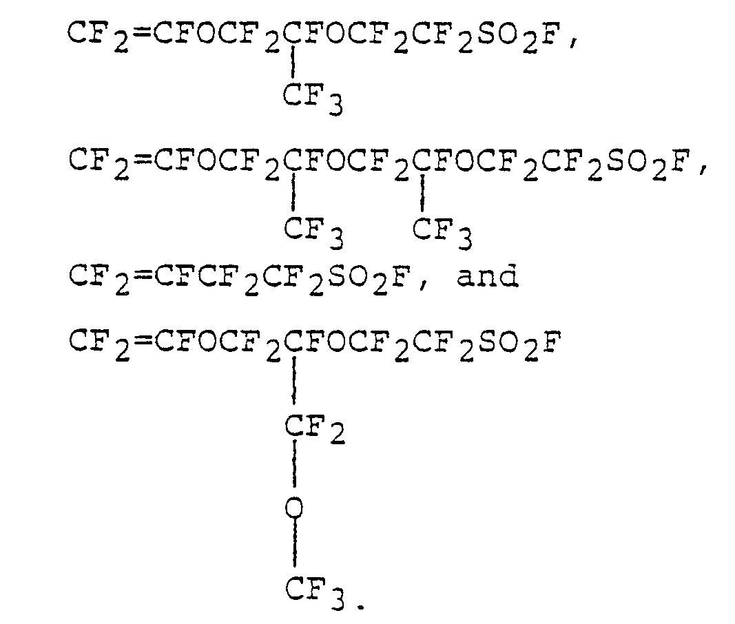
- The most preferred sulfonyl fluoride containing comonomer is perfluoro(3,6-dioxa-4-methyl-7- octenesulfonyl fluoride),

- The sulfonyl-containing monomers are disclosed in such references as U.S.P. 3,282,875, U.S.P. 3,041,317, U.S.P. 3,718,627 and U.S.P. 3,560,568.
- A preferred class of such polymers is represented by polymers having the repeating units

- m is 3 to 15,
- n is 1 to 10,
- p is 0, 1 or 2,
- the X's taken together are four fluorines or three fluorines and one chlorine,
- Y is F or CF3, and
- Rf is F, Cl or a Cl to C10 perfluoroalkyl radical.
- A most preferred copolymer is a copolymer of tetrafluoroethylene and perfluoro(3,6-dioxa-4-methyl-7- octenesulfonyl fluoride) which comprises 20 to 65 percent, preferably, 25 to 50 percent by weight of the latter.
- When used in a film or membrane to separate the anode and cathode compartments of an electrolysis cell, such as a chloralkali cell, the polymer after conversion to ionizable form should have a total ion exchange capacity of 0.5 to 1.6 meq/g (milliequivalents/ gram), preferably from 0.8 to 1.2 meq/g. Below an ion exchange capacity of 0.5 meq/g, the electrical resistivity becomes too high, and above 1.6 meq/g the mechanical properties are poor because of excessive swelling of the polymer. The values of m and n in the above formula of the copolymer should be adjusted or chosen such that the polymer has an equivalent weight no greater than about 2000, preferably no greater than about 1600, for use as an ion exchange barrier in an electrolytic cell. The equivalent weight above which the resistance of a film or membrane becomes too high for practical use in an electrolytic cell varies somewhat with the thickness of the film or membrane. For thinner films and membranes, equivalent weights up to about 2000 can be tolerated. For most purposes, however, and for films of ordinary thickness, a value no greater than about 1600 is preferred.
- Such copolymers used in the present invention can be prepared by general polymerization techniques developed for homo- and copolymerizations of fluorinated ethylenes, particularly those employed for tetrafluoroethylene which are described in the literature. Nonaqueous techniques for preparing the copolymers include that of U.S.P. 3,041,317, that is, by the polymerization of a mixture of the major monomer therein, such as tetrafluoroethylene, and a fluorinated ethylene containing a sulfonyl fluoride group in the presence of a free radical initiator, preferably a perfluorccarbon peroxide or azo compound, at a temperature in the range 0-200°C. and at pressures in the range 1-200 or more atmospheres. The nonaqueous polymerization may, if desired, be carried out in the presence of a fluorinated solvent. Suitable fluorinated solvents are inert, liquid, perfluorinated hydrocarbons, such as perfluoromethylcyclohexane, perflucrodimethyl- cyclobutane, perfluorooctane, perfluorobenzene and the like, and inert, liquid chlorofluorocarbons such as 1,1,2-trichloro-1,2,2-trifluoroethane, and the like.
- Aqueous techniques for preparing the copolymer include contacting the monomers with an aqueous medium containing a free-radical initiator to obtain a slurry of polymer particles in non-water-wet or granular form, as disclosed in U.S. Patent 2,393,967, or contacting the monomers with an aqueous medium containing both a free-radical initiator and a telogenically inactive dispersing agent, to obtain an aqueous colloidal dispersion of polymer particles, and coagulating the dispersion, as disclosed, for example, in U.S.P. 2,559,752 and U.S.P. 2,593,583.
- The melt-fabricable polymer having carboxylic functional groups is typically a polymer having a fluorinated hydrocarbon backbone chain to which are attached the functional groups or pendant side chains which in turn carry the functional groups. The pendant side chains can contain, for example


- Again in this case, as in the case of the polymers having -SO2F groups, the monomers, with the exception of the R group in the -COOR, will preferably not contain hydrogen, especially if the polymer will be used in the electrolysis of brine, and for greatest stability in harsh environments, most preferably will be free of both hydrogen and chlorine, i.e., will be perfluorinated; the R group need not be fluorinated as it is lost during hydrolysis when the functional groups are converted to ion-exchange groups.
- One exemplary suitable type of carboxyl-containing monomer is represented by the formula

- R is lower alkyl,
- Y is F or CF3, and
- s is 0, 1 or 2.
- Those monomers wherein s is 1 are preferred because their preparation and isolation in good yield is more easily accomplished than when s is 0 or 2.
- The compound
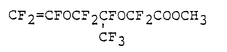

- Preparation of copolymers thereof is described in West German OLS 2817373.
- Another exemplary suitable type of carboxyl-containing monomer is represented by the formula

- V is -COOR or -CN,
- R is lower alkyl,
- Y is F or CF3,
- 8 is F or CF3, and

- s is 0, 1 or 2.
- The most preferred monomers are those wherein V is -COOR wherein R is lower alkyl, generally C1 to C5, because of ease in polymerization and conversion to ionic form. Those monomers wherein s is 1 are also preferred because their preparation and isolation in good yield is more easily accomplished than when n is 0 or 2. Preparation of those monomers wherein V is -COOR where R is lower alkyl, and copolymers thereof, is described in U. S. Patent 4,131,740. The compounds


- Yet another suitable type of carboxyl-containing monomer is that having a terminal -O(CF2)vCOOCH3 group where v is from 2 to 12, such as CF2=CF-O(CF2)3COOCH3 and CF2=CFOCF2CF (CF3)O (CF2)3COOCH3 . Preparation of such monomers and copolymers thereof is described in Japanese Patent Publications 38586/77 and 28486/77, and in British Patent 1,145,445.
- Another class of carboxyl-containing polymers is represented by polymers having the repeating units

- q is 3 to 15,
- r is 1 to 10,
- s is 0, 1 or 2,
- t is 1 to 12,
- the X's taken together are four fluorines or three fluorines and one chlorine,
- Y is F or CF3,
- Z is F or CF3, and
- R is lower alkyl.
- The values and preferred values of the ion exchange capacity and equivalent weight of the carboxylic containing copolymer should be in the same ranges as set forth above for copolymers containing sulfonyl groups in ionizable form. Similarly, the same polymerization techniques as set forth above are also suitable.
- A copolymer which contains different types of functional groups can also be used as one of the component films in making the membrane of the invention. For example, a terpolymer prepared from a monomer chosen from the first group described above, a monomer from the second group described above, and additionally a monomer of the carboxylic type from the third group described above can be prepared and used as one of the film components in making the membrane.
- It is further possible to use as one of the component films of the membrane a film which is a blend of two or more polymers. For example, a blend of a polymer having sulfonyl groups in melt-fabricable form with a polymer having carboxyl groups in melt-fabricable form can be prepared and used as one of the component films of the. membrane of this invention.
- It is additionally possible to use a laminar film as one of the component films in making the membrane. For example, a film having a layer of a copolymer having sulfonyl groups in melt-fabricable form and a layer of a copolymer having carboxyl groups in melt-fabricable form, can also be used as one of the component films in making the membrane of the invention.
- In the process of the invention, temperatures of about 240°C to 320°C are ordinarily required to fuse the polymer films employed, so as to form a unitary membrane structure with the support material, and, when more than two films are used, to make adjacent sheets of film fuse together; the temperature required may be even above or below this range, however, and will depend on the specific polymer or polymers used. Actual heater temperatures as measured by a thermocouple in the heater itself will be higher than the indicated film temperature, due to heat losses; heater temperatures will vary with the type of heater, its placement, etc., and will generally fall in the range of 350 to 500°C. In the apparatus described herein, heater temperatures of 400 to 475°C have been found suitable for making many membranes. The choice of a suitable temperature in any specific case will be clear, inasmuch as too low a temperature will fail to effect an adequate degree of adherence of the films to the reinforcement member and to each other, and too high a temperature will cause gas bubbles to form between or within the polymer films in the window areas and will cause the films to sag and form nonuniform layers.
- The reinforcement fabric for encapsulation within the membrane is suitably a woven or nonwoven fabric. Woven fabrics include those of ordinary weave, and warp knit fabrics. A woven fabric is preferred for a membrane to be used in an electrolysis cell. Fabrics prepared from either monofilament or from multistranded yarns can be used. The fabric should be able to withstand a temperature from about 240°C to about 320°C., since these temperatures are employed in the laminating steps. With this proviso, the individual reinforcing fibers can be made from conventional materials, since their main purpose is to strengthen the membrane. Due to chemical inertness, reinforcement materials made from perfluorinated polymers have been found to be preferred. The polymers include those made from tetrafluoroethylene and copolymers of tetrafluoroethylene with hexafluoropropylene and perfluoro(alkyl vinyl ethers) with alkyl being 1 to 10 carbon atoms such as perfluoro (propyl vinyl ether). An example of a most preferred reinforcement material is polytetrafluoroethylene. Supporting fibers made from chlorotrifluoroethylene polymers are also useful. Other suitable reinforcing materials include quartz and glass. Such reinforcement materials and their use to strengthen polymers in a membrane are well known in the prior art.
- Other reinforcing members in sheet-like form can also be used in the process of the invention. These include various metals and alloys such as stainless steel and titanium in the form of screen or expanded mesh, sheets of perhalogenated polymers such as polytetrafluoroethylene in the form of expanded mesh, fabric of graphite fibers, netting of various polymers such as polypropylene or oriented polyethylene, and fiberglass. Such sheet-like member can be large or small in its dimensions, and following preparation of the article having two sheets of a fluorinated polymer said polymer having sulfonyl groups in melt fabricable form, adhered to opposite sides of such reinforcing member, it can be in flat form or cut and/or shaped into other desirable forms such as small cylinders or saddles, or merely rolled into spiral form for insertion into a reactor such as a tube or column. Especially when shaping into such forms is desirable, support members having some degree of stiffness are desirable. After hydrolysis of the sulfonyl groups to sulfonate groups with a base and subsequent acidification to form sulfonic acid groups, articles of this kind are useful as a catalyst for catalyzing any chemical reaction catalyzed by hydrogen ion or a strong acid, e.g., alkylation of aromatic compounds such as the reaction of benzene and ethylene at 160°C to form ethylbenzene. Said hydrolysis with a base and acidification to form sulfonic acid groups can be carried out either before or after said cutting, shaping into desirable forms, or rolling into spiral form. For preparation of such articles with the process and apparatus disclosed herein, the reinforcing member can be of any configuration so long as air can be removed from between the two films and from within the reinforcing member through the edge-conveyor belts. Any reinforcing member having raised portions on its surface, on either a macroscopic of microscopic scale, is suitable. For example, such members can be porous, or have an open-cell structure. Sheets which are nonporous in the thickness direction, but which have surface roughness in a random or repeating pattern such as projections or furrows, so long as the air can be removed from between the two films, can also be used as the reinforcement. The fluorinated polymer having sulfonyl groups used in articles used as a catalyst is preferably a perfluorinated polymer. Catalysts made by the process disclosed herein make highly efficient use of the polymer by virtue of the polymer being largely in the form of a uniform thin layer.
- For use in ion exchange applications and in cells, for example a chloralkali cell for electrolysis of brine, the membrane should have all of the functional groups converted to ionizable functional groups. Ordinarily and preferably these will be sulfonic acid and carboxylic acid groups, or alkali metal salts thereof. Such conversion is ordinarily and conveniently accomplished by hydrolysis with acid or base, such that the various functional groups described above in relation to the melt-fabricable polymers are converted respectively to the free acids or the alkali metal salts thereof. Such hydrolysis can be carried out with an aqueous solution of a mineral acid or an alkali metal hydroxide. Base hydrolysis is preferred as it is faster and more complete. Use of hot solutions, such as near the boiling point of the solution, is preferred for rapid hydrolysis. The time required for hydrolysis increases with the thickness of the structure. It is also of advantage to include a water- miscible organic compound such as dimethylsulfoxide in the hydrolysis bath.
- Before carrying out the hydrolysis described in the previous paragraph, it is also possible to chemically modify one surface of the membrane by means other than hydrolysis. This can be especially desirable in the case of a membrane all of whose component films are prepared from polymers which contain sulfonyl functional groups and which is intended to be used in a chloralkali cell. In such a case, it is possible to treat one surface of the membrane whose functional groups are still in sulfonyl fluoride or sulfonyl chloride form with a mono- or polyfunctional amine, such as butylamine or ethylenediamine. Such techniques are described in, for example, U.S. Patents 4,085,071 and 3,969,285. Following amine treatment the membrane is then subjected to a hydrolysis 'treatment such as that described in the paragraph immediately above.
- The various copolymers used in the blends described herein should be of high enough molecular weight to produce tough films in both the melt-fabricable precursor form and in the hydrolyzed ion-exchange form.
- To further illustrate the innovative aspects of the present invention, the following examples are provided.
- A membrane of symmetrical cross-section was prepared on apparatus as described hereinabove as follows.
- A fabric woven from perfluorocarbon polymer monofilaments was encapsulated between a pair of similar films of fluorinated polymer containing sulfonyl groups. The films were each of a copolymer of perfluoro(3,6-dioxa-4-methyl-7-octenesulfonyl fluoride) and tetrafluoroethylene having an equivalent weight of 1150 and of an equal thickness of 2 mils (51 micrometers). The fabric was woven from perfluorocarbon polymer monofilament of 200 denier (.005 inches diameter, or 0.127 mm) having a thread count of 34-38 per inch (13-15 per cm) in the warp direction and 17-18 per inch (6-7 per cm) in the fill or weft direction.
- During lamination the films and fabric forming the web were passed between chevron-shaped heater plates, each of 6 inch (0.15 meter) effective heated length maintained at 460°C (heater temperature measured by thermocouple) at a rate of 12 inches/minute (5.08 X 10⁻³ meters/sec.). The amount of vacuum applied at the fabric edges through the perforated edge-conveyor belt was 26.5 inches of mercury below atmospheric pressure, or 11.5 x 10³ Pa absolute pressure.
- This laminate was then subjected to a posttreatment with a solution of ethylene diamine on one face only so as to form a catholyte barrier layer to enhance its efficiency when used as an ion-exchange membrane in a chlor-alkali cell. The treating solution contained 20 ml of ethylene diamine in 80 ml of dimethylsulfoxide which had previously been dried over a molecular sieve of 4 A (Angstrom) size. The membrane was treated for 90 minutes at room temperature in this solution. The depth of treatment penetration was 0.3 mils (7.5 microns) as measured by staining a cross-section of the membrane with Merpacyl orange R dye which showed up the modified surface layer.
- After water-washing and hydrolysis, the membrane was tested in a chlor-alkali cell for 54 days of continuous operation. The average voltage observed was 3.85 volts at an average current efficiency of 90%, equivalent to a power consumption of 2857 KW-hr/metric ton of NaOH when producing NaOH of 29% concentration at a current density of 31 amps/decimeter2 (2 ASI). Other test conditions were as follows: the inlet brine (less than 0.1 ppm calcium) was saturated and the rate was adjusted to yield an exit brine concentration of 240 gms/liter. Anolyte temperature was 80°C.
- The same apparatus and reinforcement fabric were used as in Example 1. To one side of the fabric was applied a 51-micrometer (2-mil) film of a copolymer of perfluoro(3,6-dioxa-4-methyl-7-octenesulfonyl fluoride) and tetrafluoroethylene having an equivalent weight of 1100. To the other side of the fabric was applied a pair of pre-blocked films as follows: one film was a 51-micrometer film as just described and the other film was a 25-micrometer (1-mil) film of a melt extruded blend of 75% by wt. of a copolymer of methyl perfluoro(4,7-dioxa-5-methyl-8-nonenoate) and tetrafluoroethylene having an equivalent weight of 1050 and 25% by wt. of a copolymer of perfluoro(3,6-dioxa-4-methyl-7-octenesulfonyl fluoride) and tetrafluoroethylene having an equivalent weight of 1100; the films were pre-blocked by passing them simultaneously between a pair of nip-rolls to press them together, each film being separately trained around the periphery of its respective nip-roll so that the films did not touch until the nip was reached, so as to achieve a rolling wedge effect which precludes entrainment of air between the films, because any entrained air would lead to formation of bubbled, deformed areas during formation of the membrane as a result of expansion of the air during heating; the resulting blocked "bi-film" was used in formation of the membrane with the-sulfonyl fluoride film placed against the reinforcing fabric. During lamination, the chevron-shaped heaters at the side having the 76-micrometer "bi-film" were maintained at 440°C, and on the other side at 420°C (both heater temperatures measured by thermocouple), the line speed was 5.1 mm/sec, and the vacuum at the edge conveyors was 27.5 inches of mercury below atmospheric pressure (8.2 KPa absolute pressure). The resultant laminate was hydrolyzed in a caustic solution and then tested in a chloralkali cell. After 15 days of continuous operation, the voltage was 3.68 volts, and the current efficiency 98.7%, while producing 30-32% NaOH at 31 amps/decimeter2 at 80°C, with an NaCl exit brine concentration of 230-235 gm/liter and an anolyte pH of 4.2.
- A membrane was prepared by laminating a 0.051- mm (2-mil) film of a copolymer of methyl perfluoro(4,7-dioxa-5-methyl-8-nonenoate) and tetrafluoroethylene having an equivalent weight of 1050 to each side of the same reinforcement fabric as described in Example 1.
- Lamination was carried out in the same apparatus at a line speed of 5.1 mm/sec with the heaters in each bank at 400°C, and at a vacuum at the edge conveyors of 24 inches of mercury below atmospheric pressure (20 X 103 Pa absolute pressure). After hydrolysis of the resulting membrane to the carboxylate potassium salt form, it was tested in a chloralkali cell under the standard operating conditions as detailed in Example 2, and a voltage of 4.06 volts was observed at 98.3% current efficiency after 26 days of continuous operation.
- A membrane was prepared by laminating a 0.025- mm (1-mil) film a melt-extruded blend of 75% by wt. of a copolymer of methyl perfluoro(4,7-dioxa-5-methyl-8- nonenoate) and tetrafluoroethylene having an equivalent weight of 1050 and 25% by wt. of a copolymer of perfluoro(3,6-dioxa-4-methyl-7-octenesulfonyl fluoride) and tetrafluoroethylene having an equivalent weight of 1100 to each side of the same reinforcement fabric as described in Example 1. Lamination was carried out in the same apparatus at a line speed of 5.1 nm/sec with the heaters in each bank at 420°C, and at a vacuum at the edge conveyors of 27 inches of mercury below atmospheric pressure (9.9 x 10³ Pa absolute pressure). After hydrolysis, this membrane was tested in a chlor- alkali cell under the standard conditions of Example 2, and a voltage of 3.66 volts at 94.1% current efficiency was observed after 14 days of continuous operation.
- In the apparatus of Example 1, two 0.051-mm (2-mil) films of a copolymer of perfluoro(3,6-dioxa-4-methyl-7-octenesulfonyl fluoride) and tetrafluoroethylene having an equivalent weight of 1100 were brought into contact with a non-woven uncalendered expanded sheet of titanium metal (titanium sheet having a thickness of 2.8 mils, or 0.071 mm, expanded to have openings 9.8 mils or 2.48 mm, by 4.9 mils, or 1.245 mm), one film on each side thereof. The chevron heaters were set at 475°C., and a line speed of 24 inches per minute (10.16 X 10⁻³ m/sec.) and vacuum at the edge conveyors of 24 inches of mercury below atmospheric pressure (20 x 103 Pa absolute pressure) were used. The expanded metal web provides a relatively stiff support member for the films, and following hydrolysis of the sulfonyl fluoride groups to sulfonate groups with a caustic solution and subsequent acidification to form sulfonic acid groups, the article so prepared, or after subsequent cutting and/or shpaing, is useful as a catalyst for various chemical reactions.
- With the process and apparatus described, ion exchange membranes having general utility for ion exchange purposes are prepared. Such includes selection permeation or absorption of cations, and reverse osmosis.
- A specific use for the membranes is in a chlor- alkali cell such as disclosed in German patent application 2,251,660 published April 26, 1973, and Netherlands patent application 72.17598 published June 29, 1973.
- In a manner similar to that disclosed therein, a conventional chloralkali cell is employed with the distinction of using the novel membrane described herein to separate the anode and cathode portions of the cell.
- The web supported membrane of the present invention possesses numerous technical advantages over previously known membranes. This membrane possesses exeptional uniformity. The warp and fill strands of the support fabric are well covered on both sides of the membrane by polymer. Prior art membranes made with thin layers of fluorinated polymer invariably had either bare junctions or junctions covered by only a thin polymer layer, and were thus vulnerable to abrasion and exposure of the junctions of the strands; this invariably led to rupture of the membrane and a short useful life. In the present membrane, the strands and the junctions are well covered by polymer on both sides and thus have greater resistance to abrasion and a longer useful life. Furthermore, the greater uniformity of polymer filling the window areas of the fabric, and the consequent substantial elimination of window areas having only a thin layer of polymer therein, results in the elimination of nonuniform current gradients which lead to more rapid deposition of calcium impurities in the thin areas, which in turn leads to rupture of the thin areas and short membrane life. Additionally, the greater uniformity of the surface contours of the membrane of this invention and the elimination of deep recesses in the window areas substantially reduces the tendency for gas blinding of membrane during'use in a chloralkali cell. Accordingly, the total thickness of the polymeric material can be substantially reduced over prior art membranes, with consequent improvement in efficiency and reduction of voltage when employed in electrolytic processes such as the chloralkali process. Additionally, the membranes of the invention perform well during chloralkali electrolysis when used under conditions of high depletion of the feed brine. Furthermore, the surface hydrolysis step of the prior art,process for making membranes is eliminated. Also, the process eliminates the step of stripping a membrane from a laminating drum or other support surface which in many cases led to a membrane having one surface textured or embossed by the pattern of the support surface.
Claims (31)
continuous webs of film (11 and 12) and a continuous web of reinforcing material (13) into face-to-face contact such that proximate surfaces of two of said webs of film (11,12) contact opposite sides of said web of reinforcing material (13),
Applications Claiming Priority (4)
| Application Number | Priority Date | Filing Date | Title |
|---|---|---|---|
| US10752179A | 1979-12-27 | 1979-12-27 | |
| US121461 | 1980-02-14 | ||
| US06/121,461 US4324606A (en) | 1979-12-27 | 1980-02-14 | Process for forming a reinforced membrane |
| US107521 | 1993-08-17 |
Publications (3)
| Publication Number | Publication Date |
|---|---|
| EP0031724A2 true EP0031724A2 (en) | 1981-07-08 |
| EP0031724A3 EP0031724A3 (en) | 1981-12-30 |
| EP0031724B1 EP0031724B1 (en) | 1984-08-22 |
Family
ID=26804878
Family Applications (1)
| Application Number | Title | Priority Date | Filing Date |
|---|---|---|---|
| EP80304717A Expired EP0031724B1 (en) | 1979-12-27 | 1980-12-23 | Reinforced membranes, process and apparatus for making them, and use thereof as ion-exchange membranes in chlor-alkali cells or as catalysts |
Country Status (4)
| Country | Link |
|---|---|
| US (1) | US4324606A (en) |
| EP (1) | EP0031724B1 (en) |
| CA (1) | CA1177783A (en) |
| DE (1) | DE3069046D1 (en) |
Cited By (14)
| Publication number | Priority date | Publication date | Assignee | Title |
|---|---|---|---|---|
| FR2498116A1 (en) * | 1981-01-16 | 1982-07-23 | Du Pont | PROCESS FOR PRODUCING A CATION PERMEABLE MEMBRANE COMPRISING A COATED REINFORCING TISSUE AND THE PRODUCT THUS OBTAINED |
| EP0077687A1 (en) * | 1981-10-21 | 1983-04-27 | E.I. Du Pont De Nemours And Company | Membrane assembly, electrochemical cell, and electrolysis process |
| EP0131724A3 (en) * | 1983-06-11 | 1986-10-22 | Bayer Ag | Woven diaphragm for aqueous electrolytes |
| EP0167885A3 (en) * | 1984-06-19 | 1986-12-30 | Asahi Glass Company Ltd. | Ion exchange resin membrane |
| US4913817A (en) * | 1987-06-19 | 1990-04-03 | Asahi Kasei Kogyo Kabushiki Kaisha | Reinforced ion exchange membrane and a process for producing the same |
| EP0385427A3 (en) * | 1989-02-28 | 1992-07-08 | E.I. Du Pont De Nemours And Company | Cation exchange membrane reinforced with a cation exchange fabric |
| EP0599791A3 (en) * | 1992-11-27 | 1994-06-29 | Electrolux Ab | A membrane filter for a fluid purifier and a method for its manufacture. |
| WO2011069281A1 (en) | 2009-12-11 | 2011-06-16 | 山东东岳神舟新材料有限公司 | Perfluorinated ion exchange resin, preparation method and use thereof |
| WO2011072418A1 (en) | 2009-12-15 | 2011-06-23 | 山东东岳神舟新材料有限公司 | High exchange capacity perfluorinated ion exchange resin, preparation method and use thereof |
| WO2013075809A1 (en) * | 2011-11-22 | 2013-05-30 | Maschinenfabrik Herbert Meyer Gmbh & Co. Kg | Lamination device for continuous vacuum lamination |
| WO2016210366A1 (en) * | 2015-06-25 | 2016-12-29 | Alta Devices, Inc. | Pressurized heated rolling press for manufacture and method of use |
| US11211517B2 (en) | 2015-06-25 | 2021-12-28 | Utica Leaseco, Llc | Pressurized heated rolling press for manufacture and method of use |
| US11387681B2 (en) | 2015-01-22 | 2022-07-12 | Utica Leaseco, Llc | Charging station for mobile device with solar panel |
| CN116533544A (en) * | 2023-05-08 | 2023-08-04 | 新壹洲高新材料科技(江苏)有限公司 | Foam laminating jig convenient to position |
Families Citing this family (16)
| Publication number | Priority date | Publication date | Assignee | Title |
|---|---|---|---|---|
| GB2121352B (en) * | 1982-05-25 | 1986-03-19 | Chlorine Eng Corp Ltd | Bonding of cation exchange membrane |
| US4650711A (en) * | 1985-05-31 | 1987-03-17 | The Dow Chemical Company | Method for sizing polytetrafluoroethylene fabrics |
| US4784900A (en) * | 1985-05-31 | 1988-11-15 | University Of Bath | Method for sizing polytretrafluoroethylene fabrics |
| US4650551A (en) * | 1985-05-31 | 1987-03-17 | The Dow Chemical Company | Supported ion exchange membrane films |
| US4698243A (en) * | 1986-06-20 | 1987-10-06 | The Dow Chemical Company | Method for sizing and hydrolyzing polytetrafluoroethylene fabrics, fibers, yarns, or threads |
| US4778723A (en) * | 1986-06-20 | 1988-10-18 | The Dow Chemical Company | Method for sizing polytetrafluoroethylene fibers, yarn, or threads |
| US5194189A (en) * | 1989-09-08 | 1993-03-16 | Ionics, Incorporated | Process for manufacturing continuous, supported polymeric sheet from polymerizable liquid starting materials |
| US5056996A (en) * | 1989-09-08 | 1991-10-15 | Ionics, Incorporated | Apparatus for manufacturing continuous, supported polymeric sheets from polymerizable liquid starting materials |
| US5145618A (en) * | 1989-09-08 | 1992-09-08 | Ionics, Incorporated | Process for manufacturing continuous supported ion selective membranes using non-polymerizable high boiling point solvents |
| CN101773788B (en) * | 2009-12-07 | 2010-12-29 | 山东东岳高分子材料有限公司 | Fluorine-containing ion exchange membrane with reinforced sacrificial fiber mesh cloth |
| CN101780710B (en) * | 2009-12-07 | 2012-03-07 | 山东东岳高分子材料有限公司 | Continuous preparation method and equipment for enhanced composite ionic membrane |
| DE102015014515A1 (en) * | 2015-11-11 | 2017-05-11 | Dräger Safety AG & Co. KGaA | Electrolyte conductor, method for producing an electrolyte conductor and an electrochemical gas sensor and a gas meter with such |
| KR102458763B1 (en) | 2016-08-23 | 2022-10-26 | 스완 아날라이티쉐 인스트루멘테 아크티엔게젤샤프트 | Apparatus and method for electrodeionization of liquids |
| JP6981421B2 (en) * | 2016-10-13 | 2021-12-15 | Agc株式会社 | Alkaline water electrolyzer diaphragm and alkaline water electrolyzer |
| CN107379715A (en) * | 2017-08-22 | 2017-11-24 | 张家港市升超机械设备有限公司 | A kind of continuous laminating production Wiring technology of metal three dimensional panel |
| CN114214770B (en) * | 2021-11-23 | 2023-07-18 | 山东东岳高分子材料有限公司 | A kind of high levelness reinforced net for ion exchange membrane and its application |
Family Cites Families (13)
| Publication number | Priority date | Publication date | Assignee | Title |
|---|---|---|---|---|
| US2983624A (en) * | 1956-07-16 | 1961-05-09 | Du Pont | Glass fabric gasket and diaphragm material coated with a cured elastomeric copolymerof vinylidene fluoride and hexafluoropropene and method of making same |
| DE1167005B (en) | 1961-12-08 | 1964-04-02 | Guenther Missbach Dipl Ing | Process and device for the production of two or more layers of reinforced or laminated plastic films |
| US3770567A (en) * | 1971-11-08 | 1973-11-06 | Du Pont | Laminates of support material and fluorinated polymer containing pendant side chains containing sulfonyl groups |
| US3849243A (en) * | 1971-11-08 | 1974-11-19 | Du Pont | Laminates of support material and fluorinated polymer containing pendant side chains containing sulfonyl groups |
| US3935096A (en) * | 1974-01-02 | 1976-01-27 | Hooker Chemicals & Plastics Corporation | Production of aqueous metal hydroxide solutions of low metal halide concentration |
| US4040888A (en) * | 1974-07-10 | 1977-08-09 | Ppg Industries, Inc. | Apparatus for prepressing transparent laminated assemblies |
| US3933552A (en) * | 1974-07-10 | 1976-01-20 | Ppg Industries, Inc. | Preparing transparent assemblies for lamination |
| US4021327A (en) * | 1975-04-29 | 1977-05-03 | E. I. Du Pont De Nemours And Company | Reinforced cation permeable separator |
| US4164463A (en) * | 1975-05-20 | 1979-08-14 | E. I. Du Pont De Nemours And Company | Hydrophilic fluoropolymers |
| JPS5284191A (en) * | 1975-12-30 | 1977-07-13 | Asahi Glass Co Ltd | Improved f-contg. cation exchange resin membrane |
| JPS603842B2 (en) * | 1976-09-03 | 1985-01-31 | 住友電気工業株式会社 | Asymmetric pore diameter thin film material and its manufacturing method |
| US4168216A (en) * | 1978-09-27 | 1979-09-18 | Diamond Shamrock Corporation | Heat-treated fluorocarbon sulfonamide cation exchange membrane and process therefor |
| BE871096A (en) * | 1978-10-09 | 1979-04-09 | Diamond Shamrock Corp | PROCESS FOR TREATING THE REVERSE OF A MEMBRANE REINFORCED BY A FABRIC. |
-
1980
- 1980-02-14 US US06/121,461 patent/US4324606A/en not_active Expired - Lifetime
- 1980-12-23 EP EP80304717A patent/EP0031724B1/en not_active Expired
- 1980-12-23 CA CA000367515A patent/CA1177783A/en not_active Expired
- 1980-12-23 DE DE8080304717T patent/DE3069046D1/en not_active Expired
Cited By (19)
| Publication number | Priority date | Publication date | Assignee | Title |
|---|---|---|---|---|
| FR2498116A1 (en) * | 1981-01-16 | 1982-07-23 | Du Pont | PROCESS FOR PRODUCING A CATION PERMEABLE MEMBRANE COMPRISING A COATED REINFORCING TISSUE AND THE PRODUCT THUS OBTAINED |
| EP0077687A1 (en) * | 1981-10-21 | 1983-04-27 | E.I. Du Pont De Nemours And Company | Membrane assembly, electrochemical cell, and electrolysis process |
| EP0131724A3 (en) * | 1983-06-11 | 1986-10-22 | Bayer Ag | Woven diaphragm for aqueous electrolytes |
| EP0167885A3 (en) * | 1984-06-19 | 1986-12-30 | Asahi Glass Company Ltd. | Ion exchange resin membrane |
| US4913817A (en) * | 1987-06-19 | 1990-04-03 | Asahi Kasei Kogyo Kabushiki Kaisha | Reinforced ion exchange membrane and a process for producing the same |
| EP0385427A3 (en) * | 1989-02-28 | 1992-07-08 | E.I. Du Pont De Nemours And Company | Cation exchange membrane reinforced with a cation exchange fabric |
| EP0599791A3 (en) * | 1992-11-27 | 1994-06-29 | Electrolux Ab | A membrane filter for a fluid purifier and a method for its manufacture. |
| US9023554B2 (en) | 2009-12-11 | 2015-05-05 | Shandong Huaxia Shenzhou New Material Co., Ltd. | Perfluorinated ion exchange resin, preparation method and use thereof |
| WO2011069281A1 (en) | 2009-12-11 | 2011-06-16 | 山东东岳神舟新材料有限公司 | Perfluorinated ion exchange resin, preparation method and use thereof |
| WO2011072418A1 (en) | 2009-12-15 | 2011-06-23 | 山东东岳神舟新材料有限公司 | High exchange capacity perfluorinated ion exchange resin, preparation method and use thereof |
| US9090723B2 (en) | 2009-12-15 | 2015-07-28 | Shandong Huaxia Shenzou New Material Co., Ltd. | High exchange capacity perfluorinated ion exchange resin, preparation method and use thereof |
| WO2013075809A1 (en) * | 2011-11-22 | 2013-05-30 | Maschinenfabrik Herbert Meyer Gmbh & Co. Kg | Lamination device for continuous vacuum lamination |
| US11387681B2 (en) | 2015-01-22 | 2022-07-12 | Utica Leaseco, Llc | Charging station for mobile device with solar panel |
| WO2016210366A1 (en) * | 2015-06-25 | 2016-12-29 | Alta Devices, Inc. | Pressurized heated rolling press for manufacture and method of use |
| CN108140599A (en) * | 2015-06-25 | 2018-06-08 | 阿尔塔设备公司 | Manufacturing and using method of pressure heating rolling machine |
| US10076896B2 (en) | 2015-06-25 | 2018-09-18 | Alta Devices, Inc. | Pressurized heated rolling press for manufacture and method of use |
| US11211517B2 (en) | 2015-06-25 | 2021-12-28 | Utica Leaseco, Llc | Pressurized heated rolling press for manufacture and method of use |
| CN108140599B (en) * | 2015-06-25 | 2022-07-15 | 紫石能源有限公司 | Manufacture and use method of pressure heating rolling machine |
| CN116533544A (en) * | 2023-05-08 | 2023-08-04 | 新壹洲高新材料科技(江苏)有限公司 | Foam laminating jig convenient to position |
Also Published As
| Publication number | Publication date |
|---|---|
| EP0031724B1 (en) | 1984-08-22 |
| US4324606A (en) | 1982-04-13 |
| EP0031724A3 (en) | 1981-12-30 |
| DE3069046D1 (en) | 1984-09-27 |
| CA1177783A (en) | 1984-11-13 |
Similar Documents
| Publication | Publication Date | Title |
|---|---|---|
| US4324606A (en) | Process for forming a reinforced membrane | |
| US4399183A (en) | Web-supported membrane | |
| US4437951A (en) | Membrane, electrochemical cell, and electrolysis process | |
| US3770567A (en) | Laminates of support material and fluorinated polymer containing pendant side chains containing sulfonyl groups | |
| CN111051368B (en) | Polymer containing fluorosulfonyl group or sulfonic group, process for producing the same, and use thereof | |
| US4610762A (en) | Method for forming polymer films having bubble release surfaces | |
| US4298697A (en) | Method of making sheet or shaped cation exchange membrane | |
| US4341605A (en) | Process for cation permeable membrane with reinforcement fabric embedded therein and product thereof | |
| US4168216A (en) | Heat-treated fluorocarbon sulfonamide cation exchange membrane and process therefor | |
| CA1209528A (en) | Fluorpolymer membrane with microporous stretched sheet reinforcement | |
| US4349422A (en) | Electrolysis process | |
| US4209367A (en) | Electrolysis of aqueous alkali metal halide solution | |
| US4402785A (en) | Apparatus for making a web-supported membrane | |
| US4990228A (en) | Cation exchange membrane and use | |
| US4988364A (en) | Coated cation exchange yarn and process | |
| GB1604102A (en) | Laminar structures of fluorinated ion exchange polymers | |
| US3902947A (en) | Process for preparing laminates of support material and fluorinated polymer containing pendant side chains containing sulfonyl groups | |
| CA2010844A1 (en) | Cation exchange reinforced membrane and process | |
| US5252193A (en) | Controlled roughening of reinforced cation exchange membrane | |
| US4996098A (en) | Coated cation exchange fabric and process | |
| EP0056707B1 (en) | Membrane, electrochemical cell, and electrolysis process | |
| US4444638A (en) | Electrochemical cell | |
| US4414338A (en) | Cation exchange membrane | |
| EP0385427A2 (en) | Cation exchange membrane reinforced with a cation exchange fabric | |
| US5264090A (en) | Method for the electrolysis of an alkali metal chloride using a cation exchange membrane |
Legal Events
| Date | Code | Title | Description |
|---|---|---|---|
| PUAI | Public reference made under article 153(3) epc to a published international application that has entered the european phase |
Free format text: ORIGINAL CODE: 0009012 |
|
| AK | Designated contracting states |
Designated state(s): BE DE FR GB IT NL |
|
| PUAL | Search report despatched |
Free format text: ORIGINAL CODE: 0009013 |
|
| AK | Designated contracting states |
Designated state(s): BE DE FR GB IT NL |
|
| 17P | Request for examination filed |
Effective date: 19820413 |
|
| ITF | It: translation for a ep patent filed | ||
| GRAA | (expected) grant |
Free format text: ORIGINAL CODE: 0009210 |
|
| AK | Designated contracting states |
Designated state(s): BE DE FR GB IT NL |
|
| REF | Corresponds to: |
Ref document number: 3069046 Country of ref document: DE Date of ref document: 19840927 |
|
| PGFP | Annual fee paid to national office [announced via postgrant information from national office to epo] |
Ref country code: BE Payment date: 19840930 Year of fee payment: 5 |
|
| PGFP | Annual fee paid to national office [announced via postgrant information from national office to epo] |
Ref country code: FR Payment date: 19841008 Year of fee payment: 5 |
|
| ET | Fr: translation filed | ||
| PGFP | Annual fee paid to national office [announced via postgrant information from national office to epo] |
Ref country code: DE Payment date: 19841227 Year of fee payment: 5 |
|
| PLBE | No opposition filed within time limit |
Free format text: ORIGINAL CODE: 0009261 |
|
| STAA | Information on the status of an ep patent application or granted ep patent |
Free format text: STATUS: NO OPPOSITION FILED WITHIN TIME LIMIT |
|
| 26N | No opposition filed | ||
| PGFP | Annual fee paid to national office [announced via postgrant information from national office to epo] |
Ref country code: NL Payment date: 19861231 Year of fee payment: 7 |
|
| PG25 | Lapsed in a contracting state [announced via postgrant information from national office to epo] |
Ref country code: NL Effective date: 19880701 |
|
| NLV4 | Nl: lapsed or anulled due to non-payment of the annual fee | ||
| GBPC | Gb: european patent ceased through non-payment of renewal fee | ||
| PG25 | Lapsed in a contracting state [announced via postgrant information from national office to epo] |
Ref country code: GB Free format text: LAPSE BECAUSE OF NON-PAYMENT OF DUE FEES Effective date: 19881118 |
|
| PG25 | Lapsed in a contracting state [announced via postgrant information from national office to epo] |
Ref country code: BE Effective date: 19881231 |
|
| BERE | Be: lapsed |
Owner name: E.I. DU PONT DE NEMOURS AND CY Effective date: 19881231 |
|
| PG25 | Lapsed in a contracting state [announced via postgrant information from national office to epo] |
Ref country code: FR Free format text: LAPSE BECAUSE OF NON-PAYMENT OF DUE FEES Effective date: 19890831 |
|
| REG | Reference to a national code |
Ref country code: FR Ref legal event code: ST |
|
| PG25 | Lapsed in a contracting state [announced via postgrant information from national office to epo] |
Ref country code: DE Effective date: 19900901 |