EP0031217B1 - A printing wheel for a serial printer - Google Patents
A printing wheel for a serial printer Download PDFInfo
- Publication number
- EP0031217B1 EP0031217B1 EP19800304462 EP80304462A EP0031217B1 EP 0031217 B1 EP0031217 B1 EP 0031217B1 EP 19800304462 EP19800304462 EP 19800304462 EP 80304462 A EP80304462 A EP 80304462A EP 0031217 B1 EP0031217 B1 EP 0031217B1
- Authority
- EP
- European Patent Office
- Prior art keywords
- printing wheel
- arms
- printing
- wheel
- type elements
- Prior art date
- Legal status (The legal status is an assumption and is not a legal conclusion. Google has not performed a legal analysis and makes no representation as to the accuracy of the status listed.)
- Expired
Links
Images


Classifications
-
- B—PERFORMING OPERATIONS; TRANSPORTING
- B41—PRINTING; LINING MACHINES; TYPEWRITERS; STAMPS
- B41J—TYPEWRITERS; SELECTIVE PRINTING MECHANISMS, i.e. MECHANISMS PRINTING OTHERWISE THAN FROM A FORME; CORRECTION OF TYPOGRAPHICAL ERRORS
- B41J1/00—Typewriters or selective printing mechanisms characterised by the mounting, arrangement or disposition of the types or dies
- B41J1/22—Typewriters or selective printing mechanisms characterised by the mounting, arrangement or disposition of the types or dies with types or dies mounted on carriers rotatable for selection
- B41J1/24—Typewriters or selective printing mechanisms characterised by the mounting, arrangement or disposition of the types or dies with types or dies mounted on carriers rotatable for selection the plane of the type or die face being perpendicular to the axis of rotation
- B41J1/28—Carriers stationary for impression, e.g. with the types or dies not moving relative to the carriers
- B41J1/30—Carriers stationary for impression, e.g. with the types or dies not moving relative to the carriers with the types or dies moving relative to the carriers or mounted on flexible carriers
Definitions
- the present invention relates to a printing wheel for a serial printer.
- a printing wheel used in a serial printer is driven by a DC motor in order to select a desired one type element from the many type elements on the wheel.
- a DC motor For this purpose, it is desirable to keep the outer diameter of the printing wheel small so as to make the load on the DC motor small.
- the DC driving motor must also be increased in size and the time required for selecting a type element also increases.
- Printing wheels of a variety of structures have already been proposed with a view to satisfying both these contradictory requirements. Examples of such structures will be explained with reference to Figure 1 and Figure 2.
- a pair of type elements 3a, 3b are provided on each of the many arms 2 which extend radially from a hub portion 1.
- a printing wheel having a structure as shown in Figure 1 is described in US-A-4 126 400 (see Figure 2 thereof).
- a printing wheel having a structure as shown in Figure 2 is described in US-A-4 126 400 (see Figure 11 thereof).
- Each type of printing wheel shown in Figure 1 and 2 allows more type elements to be accommodated without increasing printing wheel diameter, but each printing wheel has such disadvantages as are explained below.
- the Figure 1 printing wheel has a pair of type elements on each arm, when a type element 3a, for example, is driven by a hammer mechanism for printing towards the printing paper, type element 3b naturally comes close to the printing paper, and a printing may also be made by the type element 3b, in addition to the printing by the type element 3a, resulting in side printing.
- the printing wheel (of Figure 2) provdes only one type element on one arm and therefore can avoid the disadvantage as mentioned above, but it has a disadvantage in that the printing characteristics of type elements on arms of different length are different.
- USA4 126 400 also describes a printing wheel having two or more hub portions all of the same diameter and each carrying a set of arms, each arm with two or more type elements thereon.
- the arms of sets on different hub portions may be bent so that the type elements on all the arms lie in the same plane.
- a printing wheel for a serial printer, in which type elements, on respective arms radiating from a hub part of the printing wheel, only one type element being provided on each arm, are arranged around a plurality of circumferences of respective different diameters, characterised in that the hub part has a plurality of hub portions which support respective sets of arms, each set consisting of arms all with type elements arranged around a respective one of the said circumferences, the said hub portions being of respective different diameters and all the arms being of the same length.
- An embodiment of the present invention can provide a printing wheel which can accommodate more type elements without any increase in outer diameter, and moreover which provides the same impact printing characteristics for all type elements.
- the printing wheel 30 has a disk-like hub portion 31, many arms 32 and type elements 33.
- the arms 32 extend radially from the hub portion and only one type element 33 is provided at the end of each arm 32.
- Printing wheel 30 is obtained by combining the sub-wheels 30a and 30b as indicated in Figures 5a and 5b.
- sub-wheel 30a consists of a hub portion 31 a, arms 32a, with one type element 33a provided at the end of each arm 32a.
- the arms 32a are formed in groups of three arms, each group is provided with the same pitch with predetermined spacing, and the spacing of arms 32a in each group is the same.
- the radius of sub-wheel 30a is Wa in length, the length of the hub portion 31a is Ha and the length from a coupling portion of an arm 32a which joins the hub portion 31 a to a type element 33a is set at Aa.
- the sub-wheel 30b consists of a hub portion 31b, arms 32b with one type element 33b provided at the end of each arm 32b.
- the basic structure is the same as sub-wheel 30a, but the sub-wheels 30a and 30b are different in that the radius of sub-wheel 30b is set to Wb and the length of hub portion 31 b is set to Hb.
- the length Ab from the hub portion 31 b end of an arm 32b to the type element 33b on the arm in the sub-wheel 30b is set to be equal to the length Aa of the sub-wheel 30a.
- the sub-wheels 30a, 30b can desirably be formed by molding of plastics; each type element can be molded simultaneously.
- the sub-wheels 30a, 30b are coupled through holes 34a, 34b provided for positioning in the hub portions 31a, 31b. They are fixed and settled together by means of a bonding agent for example.
- each arm 32b of sub-wheel 30b is positioned between groups of three arms 32a of the sub-wheel 30a and it is important that type elements 33a of the sub-wheel 30a are arranged on a circumference of radius Wa, while the type elements 33b of the sub-wheel 30b are arranged on a circumference of radius Wb.
- the length of an arm 32a supporting a type element 33a is equal to the length of an arm 32b supporting a type element 33b.
- Such a printing wheel 30 is used for a serial printer as indicated in Figure 6.
- 61 is a carrier which moves reciprocally in a longitudinal direction along a platen 62.
- the carrier is supported by a guide bar 63a and a screw shaft 63b and moves when the screw shaft 63b is rotated by means of a pace motor 64 (DC motor).
- a type selection DC motor 66, a hammer mechanism 67 consisting of a plunger type magnet, and the printing wheel 30 are mounted on the carrier 61.
- the printing wheel 30 is fixed to the output shaft of the DC motor 66 for type element selection, and a desired type element is placed in a hitting position confronting a hammer 67a of the hammer mechanism 67 by rotating forwards or backwards the DC motor 66.
- the magnet is excited and the hammer 67a shifts the type element towards the platen 62.
- the arm carrying the type element deforms and the type element hits the printing paper 68 set in the platen 62, thus effecting printing.
- the DC motor 66 causes the printing wheel 30 to rotate for selection of a next type element and the space motor 64 rotates, causing the carrier 61 to move to a next print position.
- the print wheel 30 When fitting the print wheel 30 on the output shaft of the DC motor, it is important that the print wheel 30 should be fitted to the output shaft of DC motor 66 so that the sub-wheel 30a of the printing wheel 30 is located on the DC motor side 66, while the sub-wheel 30b is located on the platen 62 side.
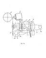
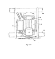
- FIGS 7a, 7b and 7c show in detail the carrier 61 of Figure 6. Parts are given the same reference numbers.
- the carrier 61 is supported by the guide bar 63a and the screw shaft 63b and is provided with a bracket 72 which can move along a shaft 71 as a centre. This bracket 72 is always urged by a spring 73 in the direction indicated by the arrow mark in Figure 7b.
- the DC motor 66 used for type element selection and the hammer mechanism 67 are fitted to the bracket 72.
- a position detector 74 is provided at the rear end of DC motor 66 and direction of rotation, speed and movement of the DC motor 66 are controlled in dependence upon an output from this position detector 74.
- the printing wheel 30 is coupled to the output shaft 66a of DC motor 66 via a universal joint 75.
- the rotating shaft of the printing wheel 30 is supported by a shift lever 76 with freedom of rotation.
- One end of the shift lever 76 is coupled to the bracket 72 with freedom of rotation, while the other end is engaged with a crank 78 which is fitted to the output shaft of shift motor 77.
- the shift motor 77, crank 78 and shift lever 76 constitute a shift mechanism.
- This shift mechanism is provided for shifting the printing wheel 30, in other words, for determining that printing is effected by a type element 33a (outer type element group) of the printing wheel 30 or by a type element 33b (inner type element group).
- the shift motor 77 is so controlled that the printing wheel 30 occupies the position indicated in Figure 7a, while in order to use a type element 33b for printing, the printing wheel 30 must be shifted up from the position indicated in Figure 7a by 180° rotation of the output shaft of the shift motor 77, and then a type element 33b must be located face to face with the hammer 67a of hammer mechanism 67.
- said universal joint 75 plays an important role. Namely the printing wheel 30 is shifted by the shift motor 77 but since the DC motor 66 for type element selection is fitted to the bracket 72, the rotating shaft of the printing wheel 30 and the output shaft of the DC motor do not form a straight line. Nevertheless, the rotation of DC motor 66 must be transmitted to the printing wheel, but this is successfully provided by the universal joint 75 which allows misalignment between shafts.
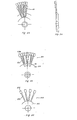
- FIG 8 shows another printing wheel embodying the present invention.
- This printing wheel 80 consists of, as indicated in Figure 8a and 8b, two sub-wheels 80a, 80b.
- the sub-wheel 80b is the same as the sub-wheel 30b of Figure 5, but the sub-wheel 80a is a little different from the sub-wheel 30a of Figure 5.
- This difference is that the hub portion 81a a and arms 82a are not in the same radial plane in the sub-wheel 80a.
- coupling portions 84 of three arms 82a are provided to a side of the hub portion 81a and a gap is formed between respective coupling portions 84.
- an arm 82b of the sub-wheel 80b is located between said coupling portions 84, and the result is as indicated in Figure 8d, the arm 82a of the sub-wheel 80a and the arm 82b of the sub-wheel 80b are substantially arranged in the same plane.
- the length of an arm 82a of the sub-wheel 80a is equal to the length of an arm 82b of the sub-wheel 80b.
- Arms 82a carry type elements 83a
- arms 82b carry type elements 83b.
- the printing wheel embodying this invention can accommodate more type elements without an increase in outer diameter of the wheel, and provides the same printing characteristics for all type elements because of the equal lengths of all arms.
- an embodiment of this invention relates to a printing wheel for a serial printer and provides a printing wheel which can accommodate many type elements without an increase in outer diameter of the printing wheel and which gives the same printing characteristics to all type elements when they are hit by a hammer mechanism.
Landscapes
- Common Mechanisms (AREA)
Description
- The present invention relates to a printing wheel for a serial printer.
- A printing wheel used in a serial printer is driven by a DC motor in order to select a desired one type element from the many type elements on the wheel. For this purpose, it is desirable to keep the outer diameter of the printing wheel small so as to make the load on the DC motor small. As the outer diameter of a printing wheel is increased the DC driving motor must also be increased in size and the time required for selecting a type element also increases.
- On the other hand, accommodation of more type elements on a printing wheel results in an increase of the outer diameter of the printing wheel, because the minimum size of type element is limited and the minimum width of arms supporting type elements is also restricted.
- Thus, a reduction in the outer size of a printing wheel and an increase in the number of type elements to be accommodated on the printing wheel are contradictory requirements.
- Printing wheels of a variety of structures have already been proposed with a view to satisfying both these contradictory requirements. Examples of such structures will be explained with reference to Figure 1 and Figure 2. In the case of the printing wheel shown in Figure 1, a pair of type elements 3a, 3b are provided on each of the
many arms 2 which extend radially from a hub portion 1. - A printing wheel having a structure as shown in Figure 1 is described in US-A-4 126 400 (see Figure 2 thereof).
- In the case of the printing wheel shown in Figure 2, only one type element 6 is provided on each of the many arms 5 extending radially from a hub portion 4, but type elements 6a and 6b are located on circumferences of different diameters.
- A printing wheel having a structure as shown in Figure 2 is described in US-A-4 126 400 (see Figure 11 thereof).
- Each type of printing wheel shown in Figure 1 and 2 allows more type elements to be accommodated without increasing printing wheel diameter, but each printing wheel has such disadvantages as are explained below.
- Namely, since the Figure 1 printing wheel has a pair of type elements on each arm, when a type element 3a, for example, is driven by a hammer mechanism for printing towards the printing paper, type element 3b naturally comes close to the printing paper, and a printing may also be made by the type element 3b, in addition to the printing by the type element 3a, resulting in side printing. Moreover, the printing wheel (of Figure 2) provdes only one type element on one arm and therefore can avoid the disadvantage as mentioned above, but it has a disadvantage in that the printing characteristics of type elements on arms of different length are different. In other words, since the distance from hub portion 4 to a type element on an arm is different for arms supporting type elements 6a and arms supporting type elements 6b, conditions of deformation of an arm when a type element 6a is hit by a hammer mechanism are different from the conditions when a type element 6b is hit. As a result, impact conditions of type elements 6a and 6b on printing paper are different, resulting in differences of contrast and/or quality of printing.
- USA4 126 400 also describes a printing wheel having two or more hub portions all of the same diameter and each carrying a set of arms, each arm with two or more type elements thereon. The arms of sets on different hub portions may be bent so that the type elements on all the arms lie in the same plane.
- According to the present invention there is provided a printing wheel, for a serial printer, in which type elements, on respective arms radiating from a hub part of the printing wheel, only one type element being provided on each arm, are arranged around a plurality of circumferences of respective different diameters, characterised in that the hub part has a plurality of hub portions which support respective sets of arms, each set consisting of arms all with type elements arranged around a respective one of the said circumferences, the said hub portions being of respective different diameters and all the arms being of the same length.
- An embodiment of the present invention can provide a printing wheel which can accommodate more type elements without any increase in outer diameter, and moreover which provides the same impact printing characteristics for all type elements.
- Reference is made, by way of example, to the accompanying drawings, in which:-
- Figure 1 is a schematic perspective view of a part of the structure of a conventional printing wheel;
- Figure 2 is a schematic view of the structure of another conventional printing wheel;
- Figure 3 is a front end on view of a printing wheel embodying the present invention;
- Figure 4 is a cross-sectional view taken along the line IV-IV of Figure 3;
- Figure 5a and 5b are respective diagrams illustrating parts of the printing wheel of Figure 3, dissassembled for clarity;
- Figure 6 is a schematic overall perspective view of a serial printer using a printing wheel embodying the present invention;
- Figures 7a, 7b and 7c show the serial printer of Figure 6 in more detail, Figure 7a is a front view,
- Figure 7b is a side view and Figure 7c is a plan view; and
- Figures 8a to 8d illustrate another embodiment of the present invention, Figure 8a is a view similar to that of Figure 3, Figures 8b and 8c are diagrams similar to those of Figures 5a and 5b, and Figure 8d is a view similar to that of Figure 4.
- A printing wheel embodying the present invention will be explained with reference to Figure 3 and Figure 4 and Figures 5a and 5b. The
printing wheel 30 has a disk-like hub portion 31,many arms 32 andtype elements 33. Thearms 32 extend radially from the hub portion and only onetype element 33 is provided at the end of eacharm 32.Printing wheel 30 is obtained by combining the sub-wheels 30a and 30b as indicated in Figures 5a and 5b. - As indicated in Figure 5a, sub-wheel 30a consists of a hub portion 31 a, arms 32a, with one type element 33a provided at the end of each arm 32a. The arms 32a are formed in groups of three arms, each group is provided with the same pitch with predetermined spacing, and the spacing of arms 32a in each group is the same. The radius of sub-wheel 30a is Wa in length, the length of the hub portion 31a is Ha and the length from a coupling portion of an arm 32a which joins the hub portion 31 a to a type element 33a is set at Aa.
- On the other hand, as indicated in Figure 5b, the sub-wheel 30b consists of a hub portion 31b,
arms 32b with one type element 33b provided at the end of eacharm 32b. The basic structure is the same as sub-wheel 30a, but the sub-wheels 30a and 30b are different in that the radius of sub-wheel 30b is set to Wb and the length of hub portion 31 b is set to Hb. - However, it is important that the length Ab from the hub portion 31 b end of an
arm 32b to the type element 33b on the arm in the sub-wheel 30b is set to be equal to the length Aa of the sub-wheel 30a. - The sub-wheels 30a, 30b can desirably be formed by molding of plastics; each type element can be molded simultaneously.
- The sub-wheels 30a, 30b are coupled through
holes arm 32b of sub-wheel 30b is positioned between groups of three arms 32a of the sub-wheel 30a and it is important that type elements 33a of the sub-wheel 30a are arranged on a circumference of radius Wa, while the type elements 33b of the sub-wheel 30b are arranged on a circumference of radius Wb. What is more important is that the length of an arm 32a supporting a type element 33a is equal to the length of anarm 32b supporting a type element 33b. - Such a
printing wheel 30 is used for a serial printer as indicated in Figure 6. - In Figure 6, 61 is a carrier which moves reciprocally in a longitudinal direction along a
platen 62. For this purpose, the carrier is supported by a guide bar 63a and ascrew shaft 63b and moves when thescrew shaft 63b is rotated by means of a pace motor 64 (DC motor). On thecarrier 61, a typeselection DC motor 66, ahammer mechanism 67 consisting of a plunger type magnet, and theprinting wheel 30 are mounted. - The
printing wheel 30 is fixed to the output shaft of theDC motor 66 for type element selection, and a desired type element is placed in a hitting position confronting a hammer 67a of thehammer mechanism 67 by rotating forwards or backwards theDC motor 66. When the positioning of the desired type element is complete, the magnet is excited and the hammer 67a shifts the type element towards theplaten 62. As a result, the arm carrying the type element deforms and the type element hits theprinting paper 68 set in theplaten 62, thus effecting printing. When one printing operation is complete, theDC motor 66 causes theprinting wheel 30 to rotate for selection of a next type element and thespace motor 64 rotates, causing thecarrier 61 to move to a next print position. - When fitting the
print wheel 30 on the output shaft of the DC motor, it is important that theprint wheel 30 should be fitted to the output shaft ofDC motor 66 so that the sub-wheel 30a of theprinting wheel 30 is located on theDC motor side 66, while the sub-wheel 30b is located on theplaten 62 side. - Figures 7a, 7b and 7c show in detail the
carrier 61 of Figure 6. Parts are given the same reference numbers. Thecarrier 61 is supported by the guide bar 63a and thescrew shaft 63b and is provided with abracket 72 which can move along ashaft 71 as a centre. Thisbracket 72 is always urged by aspring 73 in the direction indicated by the arrow mark in Figure 7b. To thebracket 72, theDC motor 66 used for type element selection and thehammer mechanism 67 are fitted. At the rear end ofDC motor 66, aposition detector 74 is provided and direction of rotation, speed and movement of theDC motor 66 are controlled in dependence upon an output from thisposition detector 74. Theprinting wheel 30 is coupled to the output shaft 66a ofDC motor 66 via auniversal joint 75. The rotating shaft of theprinting wheel 30 is supported by ashift lever 76 with freedom of rotation. One end of theshift lever 76 is coupled to thebracket 72 with freedom of rotation, while the other end is engaged with acrank 78 which is fitted to the output shaft ofshift motor 77. Theshift motor 77,crank 78 andshift lever 76 constitute a shift mechanism. This shift mechanism is provided for shifting theprinting wheel 30, in other words, for determining that printing is effected by a type element 33a (outer type element group) of theprinting wheel 30 or by a type element 33b (inner type element group). In order to use a type element 33a for printing, theshift motor 77 is so controlled that theprinting wheel 30 occupies the position indicated in Figure 7a, while in order to use a type element 33b for printing, theprinting wheel 30 must be shifted up from the position indicated in Figure 7a by 180° rotation of the output shaft of theshift motor 77, and then a type element 33b must be located face to face with the hammer 67a ofhammer mechanism 67. In this case, said universal joint 75 plays an important role. Namely theprinting wheel 30 is shifted by theshift motor 77 but since theDC motor 66 for type element selection is fitted to thebracket 72, the rotating shaft of theprinting wheel 30 and the output shaft of the DC motor do not form a straight line. Nevertheless, the rotation ofDC motor 66 must be transmitted to the printing wheel, but this is successfully provided by the universal joint 75 which allows misalignment between shafts. - Figure 8 shows another printing wheel embodying the present invention. This
printing wheel 80 consists of, as indicated in Figure 8a and 8b, two sub-wheels 80a, 80b. The sub-wheel 80b is the same as the sub-wheel 30b of Figure 5, but the sub-wheel 80a is a little different from the sub-wheel 30a of Figure 5. This difference is that the hub portion 81a a andarms 82a are not in the same radial plane in the sub-wheel 80a. In other words,coupling portions 84 of threearms 82a are provided to a side of the hub portion 81a and a gap is formed betweenrespective coupling portions 84. Therefore, when the sub-wheels 80a and 80b are combined, an arm 82b of the sub-wheel 80b is located between saidcoupling portions 84, and the result is as indicated in Figure 8d, thearm 82a of the sub-wheel 80a and the arm 82b of the sub-wheel 80b are substantially arranged in the same plane. As in the case of theprinting wheel 30 in Figure 5, the length of anarm 82a of the sub-wheel 80a is equal to the length of an arm 82b of the sub-wheel 80b.Arms 82a carry type elements 83a, and arms 82b carry type elements 83b. - As explained above, the printing wheel embodying this invention can accommodate more type elements without an increase in outer diameter of the wheel, and provides the same printing characteristics for all type elements because of the equal lengths of all arms.
- Thus, an embodiment of this invention relates to a printing wheel for a serial printer and provides a printing wheel which can accommodate many type elements without an increase in outer diameter of the printing wheel and which gives the same printing characteristics to all type elements when they are hit by a hammer mechanism.
Claims (6)
Applications Claiming Priority (4)
| Application Number | Priority Date | Filing Date | Title |
|---|---|---|---|
| JP16252679A JPS5921788B2 (en) | 1979-12-14 | 1979-12-14 | type wheel |
| JP162526/79 | 1979-12-14 | ||
| JP16252779A JPS5934504B2 (en) | 1979-12-14 | 1979-12-14 | type wheel |
| JP162527/79 | 1979-12-14 |
Publications (3)
| Publication Number | Publication Date |
|---|---|
| EP0031217A2 EP0031217A2 (en) | 1981-07-01 |
| EP0031217A3 EP0031217A3 (en) | 1982-09-22 |
| EP0031217B1 true EP0031217B1 (en) | 1985-04-24 |
Family
ID=26488289
Family Applications (1)
| Application Number | Title | Priority Date | Filing Date |
|---|---|---|---|
| EP19800304462 Expired EP0031217B1 (en) | 1979-12-14 | 1980-12-11 | A printing wheel for a serial printer |
Country Status (2)
| Country | Link |
|---|---|
| EP (1) | EP0031217B1 (en) |
| DE (1) | DE3070562D1 (en) |
Families Citing this family (1)
| Publication number | Priority date | Publication date | Assignee | Title |
|---|---|---|---|---|
| GB2134851B (en) * | 1983-01-24 | 1986-03-05 | Sanyo Electric Co | Daisy-wheel printer |
Family Cites Families (2)
| Publication number | Priority date | Publication date | Assignee | Title |
|---|---|---|---|---|
| NL7009606A (en) * | 1970-06-30 | 1972-01-03 | ||
| US4126400A (en) * | 1975-09-12 | 1978-11-21 | Ricoh Company, Ltd. | Serial printing apparatus |
-
1980
- 1980-12-11 DE DE8080304462T patent/DE3070562D1/en not_active Expired
- 1980-12-11 EP EP19800304462 patent/EP0031217B1/en not_active Expired
Also Published As
| Publication number | Publication date |
|---|---|
| DE3070562D1 (en) | 1985-05-30 |
| EP0031217A3 (en) | 1982-09-22 |
| EP0031217A2 (en) | 1981-07-01 |
Similar Documents
| Publication | Publication Date | Title |
|---|---|---|
| US4165190A (en) | Serial printing apparatus | |
| US4126400A (en) | Serial printing apparatus | |
| EP0031217A2 (en) | A printing wheel for a serial printer | |
| US4335970A (en) | Type wheel for serial printing apparatus | |
| EP0317146B1 (en) | A reel driving device for use in the slot machine | |
| CA1118698A (en) | Multiple spoked wheel printer | |
| US4228577A (en) | Method of making rotary type wheels | |
| US4127336A (en) | Type heads | |
| US4069907A (en) | High speed printer having spokes with a plurality of sections connected together at an angle greater than zero | |
| US4392756A (en) | Serial printing apparatus | |
| US4015699A (en) | Alphanumeric serial printer with a flexible membrane printing element | |
| US4436440A (en) | Shiftable daisy wheel printer | |
| US3944052A (en) | Single element flexible type drum | |
| JPS5924525Y2 (en) | type wheel | |
| EP0049351B1 (en) | Impact printer with dual helix character print elements | |
| US3794150A (en) | Axially and rotationally moveable print head | |
| JPS6274623U (en) | ||
| JPS5934504B2 (en) | type wheel | |
| EP0075465A2 (en) | Print element shifter | |
| JPS6132987B2 (en) | ||
| JPS5842121Y2 (en) | Spoke-shaped printed wheel | |
| US4902148A (en) | Typewriter with a print wheel and hammer driven by one motor | |
| JPH022708B2 (en) | ||
| GB2196299A (en) | Printing apparatus with a type wheel | |
| US5186106A (en) | Arrangement on transfer drum for in-registry sheet transfer |
Legal Events
| Date | Code | Title | Description |
|---|---|---|---|
| PUAI | Public reference made under article 153(3) epc to a published international application that has entered the european phase |
Free format text: ORIGINAL CODE: 0009012 |
|
| AK | Designated contracting states |
Designated state(s): DE FR GB IT |
|
| RBV | Designated contracting states (corrected) |
Designated state(s): DE FR GB IT |
|
| 17P | Request for examination filed |
Effective date: 19811027 |
|
| PUAL | Search report despatched |
Free format text: ORIGINAL CODE: 0009013 |
|
| AK | Designated contracting states |
Designated state(s): DE FR GB IT |
|
| ITF | It: translation for a ep patent filed | ||
| GRAA | (expected) grant |
Free format text: ORIGINAL CODE: 0009210 |
|
| AK | Designated contracting states |
Designated state(s): DE FR GB IT |
|
| REF | Corresponds to: |
Ref document number: 3070562 Country of ref document: DE Date of ref document: 19850530 |
|
| ET | Fr: translation filed | ||
| PLBE | No opposition filed within time limit |
Free format text: ORIGINAL CODE: 0009261 |
|
| STAA | Information on the status of an ep patent application or granted ep patent |
Free format text: STATUS: NO OPPOSITION FILED WITHIN TIME LIMIT |
|
| 26N | No opposition filed | ||
| ITTA | It: last paid annual fee | ||
| PGFP | Annual fee paid to national office [announced via postgrant information from national office to epo] |
Ref country code: GB Payment date: 19941201 Year of fee payment: 15 |
|
| PGFP | Annual fee paid to national office [announced via postgrant information from national office to epo] |
Ref country code: DE Payment date: 19941208 Year of fee payment: 15 |
|
| PGFP | Annual fee paid to national office [announced via postgrant information from national office to epo] |
Ref country code: FR Payment date: 19941209 Year of fee payment: 15 |
|
| PG25 | Lapsed in a contracting state [announced via postgrant information from national office to epo] |
Ref country code: GB Effective date: 19951211 |
|
| GBPC | Gb: european patent ceased through non-payment of renewal fee |
Effective date: 19951211 |
|
| PG25 | Lapsed in a contracting state [announced via postgrant information from national office to epo] |
Ref country code: FR Effective date: 19960830 |
|
| PG25 | Lapsed in a contracting state [announced via postgrant information from national office to epo] |
Ref country code: DE Effective date: 19960903 |
|
| REG | Reference to a national code |
Ref country code: FR Ref legal event code: ST |