EP0031048A1 - Device and method for storing spent fuel elements - Google Patents
Device and method for storing spent fuel elements Download PDFInfo
- Publication number
- EP0031048A1 EP0031048A1 EP80107437A EP80107437A EP0031048A1 EP 0031048 A1 EP0031048 A1 EP 0031048A1 EP 80107437 A EP80107437 A EP 80107437A EP 80107437 A EP80107437 A EP 80107437A EP 0031048 A1 EP0031048 A1 EP 0031048A1
- Authority
- EP
- European Patent Office
- Prior art keywords
- leakage detection
- detection space
- measuring device
- container
- measuring
- Prior art date
- Legal status (The legal status is an assumption and is not a legal conclusion. Google has not performed a legal analysis and makes no representation as to the accuracy of the status listed.)
- Withdrawn
Links
Images
Classifications
-
- G—PHYSICS
- G21—NUCLEAR PHYSICS; NUCLEAR ENGINEERING
- G21F—PROTECTION AGAINST X-RADIATION, GAMMA RADIATION, CORPUSCULAR RADIATION OR PARTICLE BOMBARDMENT; TREATING RADIOACTIVELY CONTAMINATED MATERIAL; DECONTAMINATION ARRANGEMENTS THEREFOR
- G21F5/00—Transportable or portable shielded containers
- G21F5/005—Containers for solid radioactive wastes, e.g. for ultimate disposal
- G21F5/008—Containers for fuel elements
Definitions
- the invention relates to a device and a method for storing spent fuel elements of a nuclear reactor using a fuel transport container with a cavity for receiving at least one fuel element and a lid for gas-tight closure of an opening leading into the cavity.
- a fuel transport container with a cavity for receiving at least one fuel element and a lid for gas-tight closure of an opening leading into the cavity.
- the gas-tight closure remains reliably effective even in the case of long-term storage, which takes, for example, several years, because otherwise radioactivity could be discharged.
- the latter must be avoided, in particular if the residual heat still emanating from the spent fuel elements is dissipated to the atmosphere via air cooling. Therefore, the invention is looking for a way to easily and reliably monitor the tightness.
- the device according to the invention is designed such that the cavity is provided with a trace gas that a leakage detection space covering the cross section of the opening is created with an additional cover and that the leakage detection space is connected to a measuring device for the trace gas for monitoring the gas-tight seal. Since the trace gas can only enter the leakage detection space via leaks, the invention makes it possible to reliably detect leaks. This results in a permanent monitoring of the function of the sealing of the transport container when the connection to the measuring device is constantly open. But even a connection that is only temporary, for example periodically, allows the leaky transport container to be separated out and / or the leakage gases to be removed in a controlled manner.
- Helium is particularly suitable as a trace gas because it is present in the air with such small proportions that even the smallest additional proportions that escape through leaks lead to a significant increase in concentration and can be determined with certainty.
- the invention can also be implemented with other trace gases.
- the leakage detection space which is preferably a recess in the additional cover, can be connected to a measuring device for one transport container each.
- a measuring device for one transport container each.
- several transport containers with their respective leakage detection spaces will advantageously be connected to a common measuring device via valves.
- the valves then allow individual containers to be connected to the measuring device in such a way that the tightness of each container can be provided and a possibly leaky container can be sorted out.
- the connecting lines of the transport containers with the measuring device form a grouping of the transport containers that can be connected overall to the measuring device, adapted to the spatial arrangement of the transport containers.
- the transport containers are preferably combined in rows.
- a measuring container can be connected upstream of the measuring device, the volume of which is advantageously a multiple of that of the leakage detection space. This can improve the accuracy of the measurement, because it is possible to store the sample gas in the measuring container for the period of the measurement after a relatively short transport time of the sample gas through the pipes that connect the leakage detection space to the measurement device, and thus disturbing leaks that result from the Pipe system come from, keep as far as possible.
- the measuring container can be brought to a high vacuum (eg P ⁇ 10 -1 mbar) before the measurement, so that the sample gas preload can be neglected. The influence of the gas in the pipeline can be reduced by evacuating with the vacuum pump.
- Leakage detection space and measuring device can be connected to a vacuum system with a vacuum pump with a lower pressure than in the cavity. Furthermore, the measuring device can be designed together with a vacuum pump and possibly a measuring container as a mobile system, which is connected to the transport container to be checked in each case with quick-action couplings.
- Working with the device according to the invention is advantageously such that the transport container with a trace gas is provided, that the leakage detection space assigned to the transport container is evacuated, that the pressure rise in the leakage detection space is then determined as a function of time, that the trace gas content in the leakage detection space is determined and that the transport container is sealed, extracted or removed if a limit value of the trace gas content is exceeded.
- Sucking off means a controlled, if necessary constant removal of the leakage gases.
- connecting lines between the leakage detection space and a device for determining the trace gas content can be evacuated.
- the leakage gases resulting from the invention can be stored for final storage without great effort because of their small amount. But you can also control, i.e. taking into account all radiation protection regulations etc. Filters and delay lines can be used if necessary to maintain the permissible delivery rates, which are monitored with activity measuring points.
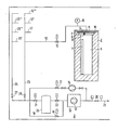
- the transport containers 2 which are also used to transport the fuel elements 1 and which each hold several, for example eight, fuel elements 1, are placed in rows in a warehouse indicated by line 3.
- the cavity is 5 the transport container 2, of which only one is shown, is closed with a cover 6 provided for transport, which is inserted into an opening 7 leading into the cavity 5 and is intended to ensure a gas-tight closure.
- a gas line accessible via a valve 8 is provided in the cover 6.
- a further cover is designated, which ends the end of the container 2 flush for transport.
- the transport container 5 Upon arrival in the warehouse 3, the transport container 5 is evacuated to, for example, 0.2 bar. Then a filling with a trace gas is introduced, which is only present in low concentrations in the surrounding atmosphere and therefore causes a noticeable increase in concentration even with small additional amounts.
- Helium is preferably used, which is filled with 10 vol.%, For example. Its concentration changes (He content in air 5 ppm) can be detected by mass spectrometry.
- a cover 10 is additionally placed on the upper end face and forms a leakage detection space 11 with a recess.
- the cover 10 covers the entire upper end face of the transport container 2, so that all leakages that can occur in the area of the opening 7 of the transport container 2 are collected with the leakage detection space 11.
- the tightness of the leakage detection space against the outside air is made as large as possible. It ensures leakage rates of a maximum of 10-2 mbar l / s.
- the leakage detection chamber 11 is connected via a pipeline 12 which is connected via a solenoid valve 13 connected to a vacuum pump 14. It is evacuated to a negative pressure P 2 of approximately 1 mbar, which is lower than the pressure P 1 in the cavity 5 and can be monitored with a pressure gauge 15 if it rises due to leakage after the valve 13 has been closed.
- the measuring device is a mass spectrometer 16, which contains a very fine vacuum pump 17 as a helium analysis device, so that the gas to be examined can be conveyed.
- trace gas concentration e.g. helium
- one of the pipeline strings 24, 25 assigned to the container rows, which each has a plurality of branch lines 12, 12 ', 12 "etc. and 26, 26', 26” etc. leading to the containers 2 , 22 and 27 or 28 including the measuring container 20 are evacuated to a pressure of approximately 1 mbar by the vacuum pump 14 or by the pump 17 of the helium analyzer 16.
- the vacuum pump 14 is equipped with sufficient pumping speed to even with a pipeline network resistance of 10 -3 - 10 -2 mbar 1 / s yet to achieve the desired final vacuum of about 1 mbar.
- the measurement gas By opening the solenoid valve 13 attached to the corresponding leakage detection space 11, the measurement gas, which is at a higher pressure level, expands in a short time via the pipeline system 12, 25 into the measurement container 20.
- the sample gas Due to the pre-evacuation, the sample gas is preloaded by residual gas in the pipes 12, 25 and in the measurement reduced gas container 20 and achieved a rapid inflow to the sample gas container 20 by the pressure level difference. This minimization of the inflow time enables the penetrating external leakage into the piping system 12, 25 to be tolerated.
- a sample gas sample in the container 20 is isolated from this sample gas stream by closing the fittings 21, 22 attached directly to the sample gas container 20.
- This container is designed with a relatively low effort in a tightness of 10- 7 mbar l / s, so that here the intrusion air falsifying the measurement can be kept away.
- the trace gas concentration increase for example helium content
- a sampling possibility is provided instead of the pipeline 12 as a mobile leakage transport system in the leakage detection space.
- One or more sample gas containers and a vacuum pump are located on a mobile unit. After being connected to the leakage detection chamber, the evacuated sample gas container serves to record the leaks, and the vacuum pump to evacuate the leakage detection chamber.
- the transport to the trace gas concentration measuring device (for example helium measurement) takes place, where by evacuation the leakage gases are transferred for the purpose of measurement and control levied delivery.
- the sampling device is designed such that the leakage gas is taken over in a short time, for example by means of quick-action couplings etc., and therefore only short inspection times are required in the radiation-endangered atmosphere of warehouse 3.
- the pipe system shown in the figure can also serve to deliver increased leakage rates from leaky containers 2 in the relatively long periods between the monitoring measurements, which are largely carried out by remote control and without the use of personnel, also by remote control.
- the outlet line 29 then leads, for example, via an activity measuring point 30 into a suitable exhaust system with filters, delay lines, chimneys, etc. not shown.
Abstract
Zur Lagerung von verbrauchten Brennelementen kann man Brennelement-Transportbehälter (2) einsetzen. Deren Dichtigkeit wird mit einem in den Transportbehälter (2) eingefüllten Spurengas, insbesondere Helium, ermittelt, das in einen Leckageerfassungsraum (11) gelangt, der als zusätzlicher Deckel (10) vorgesehen und mit einer Meßeinrichtung (16) für das Spurengas verbunden ist.Fuel storage containers (2) can be used to store spent fuel assemblies. Their tightness is determined with a trace gas, in particular helium, filled into the transport container (2) which enters a leakage detection space (11) which is provided as an additional cover (10) and is connected to a measuring device (16) for the trace gas.
Description
Die Erfindung betrifft eine Einrichtung sowie ein Verfahren zur Lagerung von verbrauchten Brennelementen eines Kernreaktors unter Verwendung eines Brennelement-Transportbehälters mit einem Hohlraum zur Aufnahme mindestens eines Brennelements und einem Deckel zum gasdichten Verschluß einer in den Hohlraum führenden Öffnung. Bei einer solchen Lagerung ist vorauszusetzen, daß der gasdichte Verschluß auch bei einer langfristigen Lagerung, die zum Beispiel mehrere Jahre dauert, zuverlässig wirksam bleibt, weil sonst Radioaktivität ausgetragen werden könnte. Letztes muß jedoch vermieden werden, insbesondere dann, wenn die von den verbrauchten Brennelementen noch ausgehende Restwärme über Luftkühlung an die Atmosphäre abgeführt wird. Deshalb sucht die Erfindung nach einer Möglichkeit zur einfachen und dennoch zuverlässigen Überwachung der Dichtigkeit.The invention relates to a device and a method for storing spent fuel elements of a nuclear reactor using a fuel transport container with a cavity for receiving at least one fuel element and a lid for gas-tight closure of an opening leading into the cavity. In the case of such storage, it must be assumed that the gas-tight closure remains reliably effective even in the case of long-term storage, which takes, for example, several years, because otherwise radioactivity could be discharged. However, the latter must be avoided, in particular if the residual heat still emanating from the spent fuel elements is dissipated to the atmosphere via air cooling. Therefore, the invention is looking for a way to easily and reliably monitor the tightness.
Die erfindungsgemäße Einrichtung ist so ausgebildet, daß der Hohlraum mit einem Spurengas versehen ist, daß mit einem zusätzlichen Deckel ein den Querschnitt der Öffnung überdeckender Leckageerfassungsraum geschaffen ist und daß der Leckageerfassungsraum zur Überwachung des gasdichten Verschlusses mit einer Meßeinrichtung für das Spurengas verbunden ist. Da das Spurengas nur über Undichtigkeiten in den Leckageerfassungsraum gelangen kann, ist mit der Erfindung eine sichere Erfassung von Undichtigkeiten möglich. Daraus ergibt sich eine ständige Funktionsüberwachung der Abdichtung des Transportbehälters, wenn die Verbindung mit der Meßeinrichtung ständig geöffnet ist. Aber auch eine nur zeitweilig, zum Beispiel periodisch bestehende Verbindung gestattet auf einfache Weise eine Aussonderung des undichten Transportbehälters und/oder eine kontrollierte Abfuhr der Leckagegase.The device according to the invention is designed such that the cavity is provided with a trace gas that a leakage detection space covering the cross section of the opening is created with an additional cover and that the leakage detection space is connected to a measuring device for the trace gas for monitoring the gas-tight seal. Since the trace gas can only enter the leakage detection space via leaks, the invention makes it possible to reliably detect leaks. This results in a permanent monitoring of the function of the sealing of the transport container when the connection to the measuring device is constantly open. But even a connection that is only temporary, for example periodically, allows the leaky transport container to be separated out and / or the leakage gases to be removed in a controlled manner.
Als Spurengas ist insbesondere Helium geeignet, weil es in der Luft mit so geringen Anteilen vorhanden ist, daß schon kleinste zusätzliche Anteile, die durch Leckagen entweichen, zu einer deutlichen Konzentrationserhöhung führen und mit Sicherheit festgestellt werden können. Im Prinzip kann die Erfindung aber auch mit anderen Spurengasen verwirklicht werden.Helium is particularly suitable as a trace gas because it is present in the air with such small proportions that even the smallest additional proportions that escape through leaks lead to a significant increase in concentration and can be determined with certainty. In principle, however, the invention can also be implemented with other trace gases.
Der Leckageerfassungsraum, der vorzugsweise eine Ausnehmung in dem zusätzlichen Deckel ist, kann für jeweils einen Transportbehälter mit einer Meßeinrichtung verbunden werden. Zur Vereinfachung wird man aber vorteilhaft mehrere Transportbehälter mit ihrem jeweiligen Leckageerfassungsraum über Ventile an eine gemeinsame Meßeinrichtung anschließen. Die Ventile gestatten es dann, einzelne Behälter mit der Meßeinrichtung so zu verbinden, daß für jeden Behälter der Dichtheitsnachweis erbracht werden und ein gegebenenfalls undichter Behälter aussortiert werden kann. Dabei ist es günstig, wenn die Verbindungsleitungen der Transportbehälter mit der Meßeinrichtung eine der räumlichen Anordnung der Transportbehälter angepaßte Gruppierung der insgesamt mit der Meßeinrichtung verbindbaren Transportbehälter bilden. Vorzugsweise sind die Transportbehälter reihenweise zusammengefaßt.The leakage detection space, which is preferably a recess in the additional cover, can be connected to a measuring device for one transport container each. For simplification, however, several transport containers with their respective leakage detection spaces will advantageously be connected to a common measuring device via valves. The valves then allow individual containers to be connected to the measuring device in such a way that the tightness of each container can be provided and a possibly leaky container can be sorted out. It is advantageous if the connecting lines of the transport containers with the measuring device form a grouping of the transport containers that can be connected overall to the measuring device, adapted to the spatial arrangement of the transport containers. The transport containers are preferably combined in rows.
Der Meßeinrichtung kann ein Meßbehälter vorgeschaltet sein, dessen Volumen vorteilhaft ein Mehrfaches von dem des Leckageerfassungsraumes ist. Damit kann man die Genauigkeit der Messung verbessern, weil es möglich ist, nach relativ kurzer Transportzeit des Meßgases durch die Rohrleitungen, die den Leckageerfassungsraum mit der Meßeinrichtung verbinden, das Meßgas im Meßbehälter für den Zeitraum der Messung aufzubewahren und so störende Leckagen, die aus dem Rohrleitungssystem herrühren, weitestgehend fernzuhalten. Zusätzlich kann der Meßbehälter vor der Messung aufgrund seiner hohen Dichtheit auf ein hohes Vakuum (z.B. P<10-1 mbar) gebracht werden, so daß die Meßgasvorbelastung vernachlässigt werden kann. Der Einfluß des Gases in der Rohrleitung kann durch Evakuieren mit der Vakuumpumpe verringert werden. Dabei können Leckageerfassungsraum und Meßeinrichtung mit einer Vakuumpumpe zu einem Unterdrucksystem mit einem kleineren Druck als im Hohlraum verbunden sein. Ferner kann die Meßeinrichtung zusammen mit einer Vakuumpumpe und gegebenenfalls einem Meßbehälter als mobiles System gestaltet sein, das mit Schnellkupplungen an den jeweils zu prüfenden Transportbehälter angeschlossen wird.A measuring container can be connected upstream of the measuring device, the volume of which is advantageously a multiple of that of the leakage detection space. This can improve the accuracy of the measurement, because it is possible to store the sample gas in the measuring container for the period of the measurement after a relatively short transport time of the sample gas through the pipes that connect the leakage detection space to the measurement device, and thus disturbing leaks that result from the Pipe system come from, keep as far as possible. In addition, the measuring container can be brought to a high vacuum (eg P <10 -1 mbar) before the measurement, so that the sample gas preload can be neglected. The influence of the gas in the pipeline can be reduced by evacuating with the vacuum pump. Leakage detection space and measuring device can be connected to a vacuum system with a vacuum pump with a lower pressure than in the cavity. Furthermore, the measuring device can be designed together with a vacuum pump and possibly a measuring container as a mobile system, which is connected to the transport container to be checked in each case with quick-action couplings.
Das Arbeiten mit der erfindungsgemäßen Einrichtung geht vorteilhaft so vor sich, daß der Transportbehälter mit einem Spurengas versehen wird, daß der dem Transportbehälter zugeordnete Leckageerfassungsraum evakuiert wird, daß danach der Druckanstieg im Leckageerfassungsraum zeitabhängig ermittelt wird, daß der Spurengasanteil im Leckageerfassungsraum ermittelt wird und daß bei Überschreiten eines Grenzwertes des Spurengasanteils der Transportbehälter besonders abgedichtet, abgesaugt oder entfernt wird. Mit Absaugen ist eine kontrollierte, gegebenenfalls ständige Abfuhr der Leckagegase gemeint. Zur Erhöhung der Genauigkeit der Leckagemessung kann man Verbindungsleitungen zwischen dem Leckageerfassungsraum und einer Einrichtung zur Ermittlung des Spurengasanteils evakuieren.Working with the device according to the invention is advantageously such that the transport container with a trace gas is provided, that the leakage detection space assigned to the transport container is evacuated, that the pressure rise in the leakage detection space is then determined as a function of time, that the trace gas content in the leakage detection space is determined and that the transport container is sealed, extracted or removed if a limit value of the trace gas content is exceeded. Sucking off means a controlled, if necessary constant removal of the leakage gases. To increase the accuracy of the leakage measurement, connecting lines between the leakage detection space and a device for determining the trace gas content can be evacuated.
Die bei der Erfindung anfallenden Leckagegase können wegen ihrer geringen Menge an sich ohne großen Aufwand für eine Endlagerung gespeichert werden. Sie können aber auch kontrolliert, d.h. unter Berücksichtigung aller Strahlenschutzbestimmungen usw. abgegeben werden. Zur Einhaltung der zulässigen Abgaberaten, die mit Aktivitätsmeßstellen überwacht wird, kann man bei Bedarf Filter und Verzögerungsstrecken einsetzen.The leakage gases resulting from the invention can be stored for final storage without great effort because of their small amount. But you can also control, i.e. taking into account all radiation protection regulations etc. Filters and delay lines can be used if necessary to maintain the permissible delivery rates, which are monitored with activity measuring points.
Zur näheren Erläuterung der Erfindung wird anhand der beiliegenden schematischen Zeichnung ein Ausführungsbeispiel beschrieben.For a more detailed explanation of the invention, an exemplary embodiment is described with reference to the accompanying schematic drawing.
Zur Zwischenlagerung der verbrauchten Brennelenente 1 eines Leichtwasserreaktors, insbesondere eines Druckwasserreaktors, werden die auch zum Transport der Brennelemente 1 dienenden Transportbehälter 2, die jeweils mehrere, zum Beispiel acht Brennelemente 1 aufnehmen, reihenweise in einer durch die Linie 3 angedeuteten Lagerhalle aufgestellt. Dabei ist der Hohlraum 5 der Transportbehälter 2, von denen nur einer dargestellt ist, mit einem für den Transport vorgesehenen Deckel 6 verschlossen, der in eine in den Hohlraum 5 führende Öffnung 7 eingesetzt ist und einen gasdichten Verschluß gewährleisten soll. Im Deckel 6 ist eine über ein Ventil 8 zugängliche Gasleitung vorgesehen. Mit 9 ist ein weiterer Deckel bezeichnet, der für den Transport die Stirnseite des Behälters 2 bündig abschließt.For intermediate storage of the
Nach der Ankunft in der Lagerhalle 3 wird der Transportbehälter 5 auf zum Beispiel 0,2 bar evakuiert. Dann wird eine Füllung mit einem Spurengas eingebracht, das nur in geringen Konzentrationen in der umgebenden Atmosphäre vorhanden ist und deshalb schon mit geringen zusätzlichen Mengen einen merklichen Konzentrationsanstieg hervorruft. Vorzugsweise wird Helium verwendet, das zum Beispiel mit 10 Vol.% eingefüllt wird. Seine Konzentrationsänderungen (He-Anteil in Luft 5 ppm) können massenspektrometrisch nachgewiesen werden.Upon arrival in the
Nach dem Füllen des Transportbehälters 2 wird auf die obere Stirnseite zusätzlich ein Deckel 10 aufgesetzt, der mit einer Ausnehmung einen Leckageerfassungsraum 11 bildet. Der Deckel 10 überdeckt die gesamte obere Stirnseite des Transportbehälters 2, so daß alle Leckagen, die im Bereich der Öffnung 7 des Transportbehälters 2 auftreten können, mit dem Leckageerfassungsraum 11 aufgefangen werden. Die Dichtheit des Leckageerfassungsraumes gegenüber der Außenluft wird so groß wie möglich gemacht. Sie sorgt für Leckageraten von höchstens 10-2 mbar l/s.After the transport container 2 has been filled, a
Der Leckageerfassungsraum 11 ist über eine Rohrleitung 12, die über ein Magnetventil 13 angeschlossen ist, mit einer Vakuumpumpe 14 verbunden. Er wird auf einen Unterdruck P2 von etwa 1 mbar evakuiert, der kleiner ist als der Druck P1 im Hohlraum 5 und mit einem Druckmesser 15 verfolgt werden kann, wenn er leckagebedingt ansteigt, nachdem das Ventil 13 geschlossen worden ist.The
Durch das Evakuieren des Leckageerfassungsraumes 11 wird die Vorbelastung der für die Leckageerfassung vorgesehenen Meßeinrichtung reduziert und damit die Nachweisempfindlichkeit entscheidend erhöht. Die Meßeinrichtung ist beim Ausführungsbeispiel ein Massenspektrometer 16, das als Helium-Analysegerät eine Feinstvakuumpumpe 17 enthält, so daß das zu untersuchende Gas gefördert werden kann.As a result of the evacuation of the
Der Meßeinrichtung 16 ist ein Meßbehälter 20 vorgeschaltet, der über Magnetventile 21 und 22 abtrennbar ist. Parallel zum Meßbehälter 20 liegt eine Umgehungsleitung 18 mit einem Magnetventil 19. Außerdem ist parallel zu der Reihenschaltung von Meßeinrichtung 16 und Meßbehälter 20 die Vakuumpumpe 14 angeordnet, die über ein Magnetventil 31 absperrbar ist. Daraus ergibt sich folgendes Verfahren zur Überwachung der Dichtheit:
- Aus dem Transportbehälter-Innenraum 5 strömt die Innenleckage, aus der Atmosphäre die Außenleckage in den
Leckageerfassungsraum 11. Dieser Mengenzuwachs führt über die Zeit zu einem Druckanstieg in denLeckageerfassungsraum 11. Wird ein Mehrfaches des Ausgangsdruckes erreicht, was über eineDruckmessung 15 ständig kontrolliert wird, beginnt der Meßvorgang.
- The internal leakage flows out of the transport container interior 5, and the external leakage flows from the atmosphere into the
leakage detection space 11. This increase in volume leads over time to an increase in pressure in theleakage detection space 11. If a multiple of the outlet pressure is reached, which is constantly controlled by apressure measurement 15, the measuring process begins.
Auf Grund des protokollierten Druckanstieges über die Zeit wird durch die Druckanstiegsmethode die Gesamtleckage ermittelt.Due to the recorded pressure increase over the Time, the total leakage is determined by the pressure increase method.
Auf Grund der Transportbehälter-Konzeption kann nicht ausgeschlossen werden, daß die ermittelte Gesamtleckage oberhalb der zulässigen Transportbehälter-Innenleckage liegt.Due to the design of the transport container, it cannot be ruled out that the total leakage determined is above the permissible internal container leakage.
Zur Unterscheidung zwischen Innen- und Außenleckage ist zusätzlich der massenspektrometrische Nachweis der Spurengaskonzentrationserhöhung (zum Beispiel Helium) notwendig.In order to differentiate between internal and external leakage, mass spectrometric detection of the increase in trace gas concentration (e.g. helium) is also necessary.
Zu diesem Zweck wird einer der den Behälterreihen zugeordneten Rohrleitungsstränge 24, 25, der jeweils mehrere zu den Behältern 2 führende Stichleitungen 12, 12', 12" usw. und 26, 26', 26" usw. aufweist, nach Öffnen der entsprechenden Ventile 21, 22 und 27 oder 28 einschließlich des Meßbehälters 20 durch die Vakuumpumpe 14 bzw. durch die Pumpe 17 des Helium-Analysegerätes 16 auf einen Druck von etwa 1 mbar evakuiert. Die Vakuumpumpe 14 ist mit ausreichendem Saugvermögen ausgestattet, um auch bei einer Leitungsnetzdichtheit von 10-3 - 10-2 mbar 1/s noch das gewünschte Endvakuum von ca. 1 mbar zu erreichen.For this purpose, after opening the
Durch Öffnen des am entsprechenden Leckageerfassungsraum 11 angebrachten Magnetventils 13 expandiert das Meßgas, welches sich auf höherem Druckniveau befindet, in kurzer Zeit über das Rohrleitungssystem 12, 25 bis in den Meßbehälter 20.By opening the
Durch die Vor-Evakuierung wird die Meßgasvorbelastung durch Restgas in den Rohrleitungen 12, 25 sowie im Meßgasbehälter 20 reduziert und durch den Druckniveauunterschied ein schnelles Zuströmen zum Meßgasbehälter 20 erreicht. Diese Minimierung der Zuströmzeit ermöglicht es, daß die eindringende Außenleckage in das Rohrleitungssystem 12, 25 toleriert werden kann.Due to the pre-evacuation, the sample gas is preloaded by residual gas in the
Aus diesem Meßgasstrom wird durch Schließen der direkt am Meßgasbehälter 20 angebrachten Armaturen 21, 22 eine Meßgasprobe im Behälter 20 isoliert. Dieser Behälter wird mit relativ geringem Aufwand in einer Dichtheit von 10-7 mbar l/s ausgeführt, so daß hier die die Messung verfälschende Einbruchsluft ferngehalten werden kann. Durch Führen des Meßgases über das Massenspektrometer 16 wird der Spurengaskonzentrationsanstieg (zum Beispiel Helium-Anteil) gegenüber der Luft ermittelt.A sample gas sample in the
Aus dem Konzentrationsanstieg des Spurengases im Meßgas in Kombination mit der durch die Druckanstiegsmethode ermittelten Gesamtleckrate läßt sich nachweisen, ob die zulässige Transportbehälterdichtheit vorhanden ist oder die zulässige Leckrate überschritten wurde.From the increase in the concentration of trace gas in the sample gas in combination with the total leak rate determined by the pressure increase method, it can be demonstrated whether the permissible tightness of the transport container is present or the permissible leak rate has been exceeded.
Bei einer Abwandlung der Erfindung ist als mobiles Leckage-Transportsystem am Leckageerfassungsraum anstelle der Rohrleitung 12 eine Probenahmemöglichkeit vorgesehen. Auf einer mobilen Einheit befindet sich ein oder mehrere Meßgasbehälter sowie eine Vakuumpumpe. Der evakuierte Meßgasbehälter dient nach Anschluß an den Leckageerfassungsraum zur Aufnahme der Leckagen, die Vakuumpumpe zum Evakuieren des Leckageerfassungsraumes. Im Meßgasbehälter folgt der Transport zur Spurengaskonzentrationsmeßeinrichturng (zum Beispiel Helium-Messung), wo durch Evakuieren die Übergabe der Leckagegase zwecks Messung und kontrollierter Abgabe erfolgt. Die Probenahmeeinrichtung ist so ausgeführt, daß zum Beispiel über Schnellschlußkupplungen etc. in kurzer Zeit die Leckagegasübernahme erfolgt und damit nur kurze Begehungszeiten in der strahlengefährdeten Atmosphäre der Lagerhalle 3 benötigt werden.In a modification of the invention, a sampling possibility is provided instead of the
Es können aber auch mehrere Behälter 2 mit jeweils separaten Absperrarmaturen 13 über ein Rohrleitungssystem mit einer gemeinsamen Rohrleitung zusammengefaßt werden, die bis in einen Bereich mit geringerer Strahlenbelastung geführt wird. An diesem Ort erfolgt der Anschluß eines mobilen Leckagegastransportsystems und wie oben beschrieben, die Übernahme, dann Auswertung und Abgabe der Leckagegase.However, it is also possible to combine a plurality of containers 2, each with separate shut-off
Das in der Figur dargestellte Rohrleitungssystem kann auch dazu dienen, erhöhte Leckageraten aus undichten Behältern 2 in den relativ langen Zeiträumen zwischen den Überwachungsmessungen, die weitgehend durch Fernbedienung und ohne Personaleinsatz erfolgen, ebenfalls durch Fernbedienung kontrolliert abzugeben. Die Auslaßleitung 29 führt dann zum Beispiel über eine Aktivitätsmeßstelle 30 in ein geeignetes Abgassystem mit nicht dargestellten Filtern, Verzögerungsstrecken, Kaminen usw..The pipe system shown in the figure can also serve to deliver increased leakage rates from leaky containers 2 in the relatively long periods between the monitoring measurements, which are largely carried out by remote control and without the use of personnel, also by remote control. The
Claims (12)
Applications Claiming Priority (2)
| Application Number | Priority Date | Filing Date | Title |
|---|---|---|---|
| DE2950198 | 1979-12-13 | ||
| DE19792950198 DE2950198A1 (en) | 1979-12-13 | 1979-12-13 | DEVICE AND METHOD FOR STORING USED FUEL ELEMENTS |
Publications (1)
| Publication Number | Publication Date |
|---|---|
| EP0031048A1 true EP0031048A1 (en) | 1981-07-01 |
Family
ID=6088403
Family Applications (1)
| Application Number | Title | Priority Date | Filing Date |
|---|---|---|---|
| EP80107437A Withdrawn EP0031048A1 (en) | 1979-12-13 | 1980-11-27 | Device and method for storing spent fuel elements |
Country Status (4)
| Country | Link |
|---|---|
| US (1) | US4427893A (en) |
| EP (1) | EP0031048A1 (en) |
| JP (1) | JPS5693085A (en) |
| DE (1) | DE2950198A1 (en) |
Cited By (6)
| Publication number | Priority date | Publication date | Assignee | Title |
|---|---|---|---|---|
| FR2486701A1 (en) * | 1980-07-08 | 1982-01-15 | Nuklear Service Gmbh Gns | ARMORED CONTAINER FOR THE TRANSPORT AND STORAGE OF RADIOACTIVE SUBSTANCES |
| FR2552519A1 (en) * | 1983-09-22 | 1985-03-29 | Commissariat Energie Atomique | DEVICE FOR SEALING A CONFINEMENT ENCLOSURE |
| GB2166680A (en) * | 1984-11-13 | 1986-05-14 | Westinghouse Electric Corp | Closure system for a spent fuel storage cask |
| US4983352A (en) * | 1984-11-13 | 1991-01-08 | Westinghouse Electric Corp. | Closure system for a spent fuel storage cask |
| EP0468233A2 (en) * | 1990-07-26 | 1992-01-29 | Westinghouse Electric Corporation | Cask for storage or transport of radioactive materials |
| EP0978849A1 (en) * | 1998-08-01 | 2000-02-09 | GNB Gesellschaft für Nuklear-Behälter mbH | Container for the final storage of spent fuel elements from nuclear powerplants |
Families Citing this family (5)
| Publication number | Priority date | Publication date | Assignee | Title |
|---|---|---|---|---|
| US4576274A (en) * | 1983-05-26 | 1986-03-18 | Cart-O-Matic Aktiebolag | Means for the storing of carts such as shopping carts |
| GB8402669D0 (en) * | 1984-02-01 | 1984-03-07 | English Electric Co Ltd | Storage arrangements for nuclear fuel |
| KR930003174A (en) * | 1991-07-18 | 1993-02-24 | 데릭 제임스 맥코맥 | Nuclear fuel container |
| FR2777090B1 (en) * | 1998-04-07 | 2000-05-05 | Commissariat Energie Atomique | METHOD OF MEASURING THE TRITIUM ACTIVITY OF A RADIOACTIVE WASTE DRUM |
| CN114112226A (en) * | 2021-12-08 | 2022-03-01 | 中国原子能科学研究院 | Device and method for detecting damage of spent fuel element |
Citations (1)
| Publication number | Priority date | Publication date | Assignee | Title |
|---|---|---|---|---|
| DE2854358A1 (en) * | 1977-12-16 | 1979-06-21 | Nl Industries Inc | TRANSPORT CONTAINER FOR RADIOACTIVE MATERIALS |
-
1979
- 1979-12-13 DE DE19792950198 patent/DE2950198A1/en not_active Ceased
-
1980
- 1980-11-27 EP EP80107437A patent/EP0031048A1/en not_active Withdrawn
- 1980-12-10 US US06/215,136 patent/US4427893A/en not_active Expired - Lifetime
- 1980-12-12 JP JP17646280A patent/JPS5693085A/en active Pending
Patent Citations (1)
| Publication number | Priority date | Publication date | Assignee | Title |
|---|---|---|---|---|
| DE2854358A1 (en) * | 1977-12-16 | 1979-06-21 | Nl Industries Inc | TRANSPORT CONTAINER FOR RADIOACTIVE MATERIALS |
Cited By (9)
| Publication number | Priority date | Publication date | Assignee | Title |
|---|---|---|---|---|
| FR2486701A1 (en) * | 1980-07-08 | 1982-01-15 | Nuklear Service Gmbh Gns | ARMORED CONTAINER FOR THE TRANSPORT AND STORAGE OF RADIOACTIVE SUBSTANCES |
| FR2552519A1 (en) * | 1983-09-22 | 1985-03-29 | Commissariat Energie Atomique | DEVICE FOR SEALING A CONFINEMENT ENCLOSURE |
| EP0147250A1 (en) * | 1983-09-22 | 1985-07-03 | Commissariat A L'energie Atomique | Confinement vessel for dangerous, especially radioactive products |
| GB2166680A (en) * | 1984-11-13 | 1986-05-14 | Westinghouse Electric Corp | Closure system for a spent fuel storage cask |
| US4983352A (en) * | 1984-11-13 | 1991-01-08 | Westinghouse Electric Corp. | Closure system for a spent fuel storage cask |
| EP0468233A2 (en) * | 1990-07-26 | 1992-01-29 | Westinghouse Electric Corporation | Cask for storage or transport of radioactive materials |
| US5089214A (en) * | 1990-07-26 | 1992-02-18 | Westinghouse Electric Corp. | Apparatus for monitoring the pressure within a cask containing radioactive material |
| EP0468233A3 (en) * | 1990-07-26 | 1992-11-04 | Westinghouse Electric Corporation | Apparatus and method for monitoring the pressure within a cask containing potentially hazardous gas |
| EP0978849A1 (en) * | 1998-08-01 | 2000-02-09 | GNB Gesellschaft für Nuklear-Behälter mbH | Container for the final storage of spent fuel elements from nuclear powerplants |
Also Published As
| Publication number | Publication date |
|---|---|
| JPS5693085A (en) | 1981-07-28 |
| DE2950198A1 (en) | 1981-06-19 |
| US4427893A (en) | 1984-01-24 |
Similar Documents
| Publication | Publication Date | Title |
|---|---|---|
| DE3828588C1 (en) | ||
| EP1238253B1 (en) | Method for detecting and localising leaks and suitable devices for carrying out said method | |
| DE3421533A1 (en) | COUNTER-CURRENT LEAK DETECTOR WITH REFRIGERATOR | |
| EP0931253B1 (en) | Process for testing the tightness of packages | |
| EP2994736B1 (en) | Leak test assembly and leak testing method | |
| EP0285864A1 (en) | Method and device for detecting leakage in liquid systems | |
| EP2989638B1 (en) | Nuclear power plant with emission monitoring system of a venting system | |
| DE112014004741T5 (en) | Leakage test device and method | |
| EP0031048A1 (en) | Device and method for storing spent fuel elements | |
| DE102009004363A1 (en) | Leak detection method | |
| WO2000022398A1 (en) | Film leak detector | |
| DE19542330A1 (en) | Detector for testing individual PWR fuel elements for leakage | |
| EP0598789B1 (en) | Process and device for obtaining samples from the atmosphere in a closed gastight container, especially from the reactor safety vessel of a nuclear power station | |
| DE2441124B2 (en) | Leak detection device | |
| DE2403360A1 (en) | LEAK INSPECTION PROCEDURE | |
| WO2016096499A1 (en) | Device and method for performing a leak test on fuel rod capsules | |
| EP2801808A1 (en) | Leak test assembly and leak testing method | |
| DE102013104682B3 (en) | Calibration device for testing tightness of structural component or closed package of car rim, has test gas supply line with individual insertion elements applied with compressed air, and test gas and is arranged in test gas chamber | |
| DE2441123A1 (en) | PROCEDURE FOR TESTING OBJECTS FOR LEAKAGE | |
| DE2245822B2 (en) | METHOD OF DETECTING LEAKS AND APPROPRIATE LEAK DETECTOR ARRANGEMENT FOR ITS IMPLEMENTATION | |
| EP1240491B1 (en) | Method for operating a film leak indicator and a corresponding film leak indicator for carrying out said method | |
| EP1119754A1 (en) | Method and device for integrally detecting test gas leaks | |
| EP0646781A2 (en) | Method and arrangement for examining the tightness of a gas withdrawing system of a gas analysing device | |
| EP1964130A1 (en) | Device for testing the tightness of fuel rod capsules | |
| DE2846826B2 (en) | Process and device for determining the proportion of non-condensable gases in vapors |
Legal Events
| Date | Code | Title | Description |
|---|---|---|---|
| PUAI | Public reference made under article 153(3) epc to a published international application that has entered the european phase |
Free format text: ORIGINAL CODE: 0009012 |
|
| AK | Designated contracting states |
Designated state(s): SE |
|
| 17P | Request for examination filed |
Effective date: 19811030 |
|
| STAA | Information on the status of an ep patent application or granted ep patent |
Free format text: STATUS: THE APPLICATION IS DEEMED TO BE WITHDRAWN |
|
| 18D | Application deemed to be withdrawn |
Effective date: 19840613 |
|
| RIN1 | Information on inventor provided before grant (corrected) |
Inventor name: QUEISER, HORST Inventor name: ECKHARDT, BERND |