EP0030750B1 - Threshold circuit for radar video signals - Google Patents
Threshold circuit for radar video signals Download PDFInfo
- Publication number
- EP0030750B1 EP0030750B1 EP80201121A EP80201121A EP0030750B1 EP 0030750 B1 EP0030750 B1 EP 0030750B1 EP 80201121 A EP80201121 A EP 80201121A EP 80201121 A EP80201121 A EP 80201121A EP 0030750 B1 EP0030750 B1 EP 0030750B1
- Authority
- EP
- European Patent Office
- Prior art keywords
- zone
- average
- circuit
- echo strength
- azimuth
- Prior art date
- Legal status (The legal status is an assumption and is not a legal conclusion. Google has not performed a legal analysis and makes no representation as to the accuracy of the status listed.)
- Expired
Links
- 238000012935 Averaging Methods 0.000 claims description 57
- 230000015654 memory Effects 0.000 claims description 14
- 238000000034 method Methods 0.000 description 22
- 230000000694 effects Effects 0.000 description 3
- 238000010586 diagram Methods 0.000 description 2
- 230000006870 function Effects 0.000 description 2
- 230000003044 adaptive effect Effects 0.000 description 1
- 238000002592 echocardiography Methods 0.000 description 1
- 230000001629 suppression Effects 0.000 description 1
Images
Classifications
-
- G—PHYSICS
- G01—MEASURING; TESTING
- G01S—RADIO DIRECTION-FINDING; RADIO NAVIGATION; DETERMINING DISTANCE OR VELOCITY BY USE OF RADIO WAVES; LOCATING OR PRESENCE-DETECTING BY USE OF THE REFLECTION OR RERADIATION OF RADIO WAVES; ANALOGOUS ARRANGEMENTS USING OTHER WAVES
- G01S7/00—Details of systems according to groups G01S13/00, G01S15/00, G01S17/00
- G01S7/02—Details of systems according to groups G01S13/00, G01S15/00, G01S17/00 of systems according to group G01S13/00
- G01S7/28—Details of pulse systems
- G01S7/285—Receivers
- G01S7/292—Extracting wanted echo-signals
- G01S7/2923—Extracting wanted echo-signals based on data belonging to a number of consecutive radar periods
- G01S7/2927—Extracting wanted echo-signals based on data belonging to a number of consecutive radar periods by deriving and controlling a threshold value
Definitions
- the invention relates to a threshold circuit for radar video signals, where the radar coverage is divided into zones constituted by azimuth sectors and range rings, the zones being subdivided into cells formed by azimuth and range increments, which threshold circuit comprises a first cell-averaging circuit for determining, from the video signals received in the individual cells, the average echo strength in each zone pertaining to the azimuth sector that has been scanned by the radar beam.
- the German Auslegeschrift 24 40 742 and the German Offenlegungsschrift 28 50 508 describe circuits for the suppression of clutter areas and stationary targets, where the radar coverage is divided as stated above and where the average echo strength is determined in each zone.
- this average echo strength is compared with that of zones adjoining in azimuth and range to establish the presence of clutter areas.
- the average echo strength obtained for each zone is integrated over several antenna revolutions to indicate the presence of stationary targets.
- An object of the present invention is to derive a threshold level from the average echo strength established in each zone, above which level the echo signals from both stationary and moving targets are passed if these signals exceed the average echo strength.
- the threshold circuit should be suitable for radar video signals from targets at sea or in a harbour, considering both point targets and extended targets. Since one threshold level is determined for each zone, it is necessary that for the proper functioning of the threshold circuit the clutter distribution in the zone be substantially homogenous; for this reason the size of the zones must be kept within limits. A consequence of this is however that extended targets may cover a zone fully or for the larger part. It is therefore another object of the present invention to derive, also for such cases, a threshold level from the average echo strength established in each zone.
- the threshold circuit as set forth in the opening paragraph is characterised by a first zone-averaging circuit connected to the first cell-averaging circuit for determining, from the last established average echo strength of a zone, from the average echo strength of said zone as established after the previous scanning of the relevant azimuth sector by the radar beam, and from the average echo strengths of zones adjoining in azimuth and range, a new average echo strength of the zone, from which new average echo strength a threshold level is derived, which threshold level is applied to a gate circuit to pass the video signals received in the individual cells of the relevant zone if said video signals exceed said threshold level.
- the threshold circuit according to the invention is hereinafter referred to as a three-dimensional (3D) threshold circuit.
- the averaging process over the zones adjoining in azimuth and range occurs to avoid excessive differences in threshold levels between neighbouring zones, and to derive a threshold level in case an extended target covers a zone completely or for the larger part.
- the radar video signals are from targets situated in a harbour, it is desirable to blank the zones extending over the land area covered by the radar to exclude them from the averaging processes. If however an extended target fills a zone adjoining a blanked zone, a surrounding part of the target will be lacking so that the averaging process will not be complete. In such a case, a greater weighting factor must be applied to the unblanked target area involved in the averaging process. This may be done in an indirect way by including in the averaging process the average echo strength obtained at a previous time.
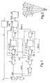
- the threshold circuit of Fig. 1 comprises a first cell-averaging circuit 1. This circuit is supplied with the video signals received in the individual cells. In the embodiment in question, these video signals are not supplied direct but via a limiter 2.
- limiter 2 the amplitude of the video signals VID received in each cell is limited to a value CL, determined in a summing network 3 by the average echo strength T t (r,n) of the relevant zone increased by a preset constant CLDR, the average echo strength T t (r,n) being established in a manner to be described hereinafter.
- the amplitude limitation by the CL signal is to prevent that the threshold level determined in each zone by the threshold circuit be raised to an excessive value.
- the limitation is adaptive, as it depends on the average value of the echo strength. Another reason for using limiter 2 is to prevent the "shadow" effect; this is the effect of an increased threshold level in the vicinity of targets.
- the CLDR value is so selected that clutter echoes are not limited.
- the output signals of limiter 2 applied to the first cell-averaging circuit 1 can be expressed by:
- the video signal received in the cell (p,q) of the relevant zone is expressed by:
- the MT signal delivered by cell-averaging circuit 1 can then be expressed by:
- the number of cells involved in the summation need not per se correspond with the here defined number of cells per zone, viz. A.B. This number may slightly vary through variations in the rotational speed of the antenna through wind load. Besides, a number of cells may be blanked. The summation is therefore performed over a number of cells slightly less than A.B. If this number is not reached through blanking, the results of the averaging process are of no concern. For instance, a zone may be covered fully or for the greater part by land, while the average echo strength is to be established at sea or in a harbour.
- a blanking circuit (not shown) is used to generate signals which are applied via line 4 to the first cell-averaging circuit 1 to indicate the blanked areas.
- Cell-averaging circuit 1 delivers a signal VAL which is "0" when through the blanking the MT signal is meaningless and is "1" when this signal is of interest.
- the MT signal representing the last established average echo strength in each zone, is applied to the first zone-averaging circuit 5. From the MT signal, the average echo strength T t (r,n) of the relevant zone, as determined after the previous scanning of the relevant azimuth sector by the radar beam, and from the average echo strengths of zones adjoining in azimuth and range, the first zone-averaging circuit determines a new average echo strength GT t+1 (r,n) in the zone.
- the first zone-averaging circuit 5 thereto comprises a first computing means 6, a T memory 7 and a second computing means 8.
- Fig. 2 illustrating the zones of three azimuth sectors n-1, n and n+1, and three range rings r-1, r and r+1.
- the shaded portion (r,n) is the zone for which the new average echo strength GT t+1 (r,n) must be determined.
- the average echo strength of the zones already scanned by the radar is determined at time t+1; the average echo strengths established during the previous radar antenna revolution at time t still apply to the zones yet to be scanned by the radar.
- the new average echo strength GT t+ ,(r,n) to be established for zone (r,n) is a function of the average echo strength of the surrounding zones and of the previously established values of the average echo strength of zone (r,n).
- GT t+1 (r,n) is a function of the average echo strength of the zones (r,n-1) and (r,n+ 1) adjoining in azimuth, viz.
- T t+1 (r,n-1 ) and Tt(r,n+ 1) of the value T t (r,n) established during the previous antenna revolution, and of the average echo strength of the zones adjoining in range ..., (r-3,n), (r-2,n), (r-1,n), (r+1,n), (r+2,n), (r+3,n),..., viz...., T t+1 (r-3,n), T t+1 (r-2,n), T t+1 (r-1,n), T t (r+1,n), T t (r+2,n), T t (r+3,n), ....
- ⁇ and ⁇ are adjustable weighting factors.
- T memory 7 This memory thereto contains a value T(r,n) for each zone.
- T t+1 (r,n) the value of memory 7 is supplied to computing means 6.
- second computing means 8 an averaging process is performed on the zones adjoining in range.
- the output signal of computing means 8 may be expressed by: where N is an even number.
- This output signal is applied to combining circuit 9.
- This circuit in turn generates a threshold value DR, which is supplied to gate circuit 10 to pass the video signals VID from the individual cells of a zone if these signals exceed the threshold DR.
- the threshold DR can be determined more accurately if it is based not only on the average echo strength of a zone, but also on the average absolute difference between the video signals received in the individual cells and the average echo strength of this zone. This is connected with the fact that from a mathematical point of view the clutter has the characteristics of a Weibull distribution.
- a second cell-averaging circuit 12 and a second zone-averaging circuit 13 are incorporated.
- Cell-averaging circuit 12 determines the average absolute difference between the video signals VIDL, received in the individual cells and delivered by limiter 2, and the average echo strength T t (r,n) of the relevant zone.
- the value from the subtracting circuit 14 is thereto applied to the cell-averaging circuit 12.
- cell-averaging circuit 12 delivers a signal MD, which can be expressed by:
- the averaging process is performed on the same number of cells as in the case of averaging circuit 1.
- the aforementioned signals indicative of the blanked areas are supplied via line 15.
- second zone-averaging circuit 13 also consists of a first computing means 16, a D memory 17 and a second computing means 18.
- computing means 16 the averaging process is performed on the zones adjoining in azimuth and on the time.
- ⁇ ' and A' are weighting factors.
- D memory 17 This memory thus contains a value D(r,n) for each zone.
- computing means 16 is supplied with the D t (r,n) value from memory 17.
- computing means 18 the averaging process is performed on the zones adjoining in range.
- the output signal of computing means 18 can be expressed by: where N is an even number.
- This signal is applied to combining circuit 9 which derives a threshold value DR from this signal and from the GT L+ ,(r,n) signal of computing means 8.
- zone offset values CO(r,n) determined by a computer can be stored for each zone. These values are supplied to the combining circuit 9, where they are used to establish the threshold value DR.
- the threshold DR can be expressed by: where the constant is selectable, depending on the desired false alarm rate and the nature of the clutter.
- the values T t+1 (r,n-1 ) and D t+1 (r,n-1) in the expression of signals T t+1 (r,n) and D t+1 (r,n) supplied by computing means 6 and 16, respectively, are substituted by T t (r,n) and Dt(r,n), respectively.
- zone (r,n+ 1) if the MT and DT values of zone (r,n+ 1) are undefined, the values T t (r,n+ 1) and D t (r,n+ 1) in the expression for T t+1 (r,n) and D t+1 (r,n) respectively, are substituted by T t (r,n) and D t (r,n) respectively.
- zone (r,n) is blanked, the MT and DT values of this zone are indeed undefined, but this does not imply the values T t (r,n) and D t (r,n); in this case the latter values are fully determined by the zones adjoining in azimuth.
Landscapes
- Engineering & Computer Science (AREA)
- Radar, Positioning & Navigation (AREA)
- Remote Sensing (AREA)
- Computer Networks & Wireless Communication (AREA)
- Physics & Mathematics (AREA)
- General Physics & Mathematics (AREA)
- Radar Systems Or Details Thereof (AREA)
Description
- The invention relates to a threshold circuit for radar video signals, where the radar coverage is divided into zones constituted by azimuth sectors and range rings, the zones being subdivided into cells formed by azimuth and range increments, which threshold circuit comprises a first cell-averaging circuit for determining, from the video signals received in the individual cells, the average echo strength in each zone pertaining to the azimuth sector that has been scanned by the radar beam.
- The German Auslegeschrift 24 40 742 and the German Offenlegungsschrift 28 50 508 describe circuits for the suppression of clutter areas and stationary targets, where the radar coverage is divided as stated above and where the average echo strength is determined in each zone. In the circuit described in the Auslegeschrift this average echo strength is compared with that of zones adjoining in azimuth and range to establish the presence of clutter areas. In the circuit described in the Offenlegungsschrift the average echo strength obtained for each zone is integrated over several antenna revolutions to indicate the presence of stationary targets. An object of the present invention is to derive a threshold level from the average echo strength established in each zone, above which level the echo signals from both stationary and moving targets are passed if these signals exceed the average echo strength.
- The threshold circuit should be suitable for radar video signals from targets at sea or in a harbour, considering both point targets and extended targets. Since one threshold level is determined for each zone, it is necessary that for the proper functioning of the threshold circuit the clutter distribution in the zone be substantially homogenous; for this reason the size of the zones must be kept within limits. A consequence of this is however that extended targets may cover a zone fully or for the larger part. It is therefore another object of the present invention to derive, also for such cases, a threshold level from the average echo strength established in each zone.
- To realise the above objects, the threshold circuit as set forth in the opening paragraph is characterised by a first zone-averaging circuit connected to the first cell-averaging circuit for determining, from the last established average echo strength of a zone, from the average echo strength of said zone as established after the previous scanning of the relevant azimuth sector by the radar beam, and from the average echo strengths of zones adjoining in azimuth and range, a new average echo strength of the zone, from which new average echo strength a threshold level is derived, which threshold level is applied to a gate circuit to pass the video signals received in the individual cells of the relevant zone if said video signals exceed said threshold level.
- In each zone the average echo strength is established with each antenna revolution. To do so, an averaging process is first performed over the cells of a zone. This is followed by an averaging process over the zones adjoining in azimuth and range and over the average value obtained previously, thus over azimuth, range and time. Hence, the threshold circuit according to the invention is hereinafter referred to as a three-dimensional (3D) threshold circuit.
- The averaging process over the zones adjoining in azimuth and range occurs to avoid excessive differences in threshold levels between neighbouring zones, and to derive a threshold level in case an extended target covers a zone completely or for the larger part. If the radar video signals are from targets situated in a harbour, it is desirable to blank the zones extending over the land area covered by the radar to exclude them from the averaging processes. If however an extended target fills a zone adjoining a blanked zone, a surrounding part of the target will be lacking so that the averaging process will not be complete. In such a case, a greater weighting factor must be applied to the unblanked target area involved in the averaging process. This may be done in an indirect way by including in the averaging process the average echo strength obtained at a previous time.
- The invention will now be explained with reference to the accompanying figures, of which:
- Fig. 1 is a block diagram illustrating an embodiment of the threshold circuit according to the invention, and
- Fig. 2 is a diagram which is useful in explaining the functioning of certain parts of the threshold circuit of Fig. 1.
- The coverage of the radar system, of which the 3D threshold circuit forms a part, is divided into zones made up of azimuth sectors and range rings, which zones are subdivided into cells formed by azimuth and range increments. To be able to determine the instantaneous average echo strength in each zone, the threshold circuit of Fig. 1 comprises a first cell-
averaging circuit 1. This circuit is supplied with the video signals received in the individual cells. In the embodiment in question, these video signals are not supplied direct but via alimiter 2. Inlimiter 2 the amplitude of the video signals VID received in each cell is limited to a value CL, determined in a summing network 3 by the average echo strength Tt(r,n) of the relevant zone increased by a preset constant CLDR, the average echo strength Tt(r,n) being established in a manner to be described hereinafter. The amplitude limitation by the CL signal is to prevent that the threshold level determined in each zone by the threshold circuit be raised to an excessive value. The limitation is adaptive, as it depends on the average value of the echo strength. Another reason for usinglimiter 2 is to prevent the "shadow" effect; this is the effect of an increased threshold level in the vicinity of targets. The CLDR value is so selected that clutter echoes are not limited. The output signals oflimiter 2 applied to the first cell-averagingcircuit 1 can be expressed by:
- The range interval of a cell within the range ring i+1 is indicated by i.A+p, where i.A represents the range, expressed in range increments, of the first i range rings, A the total number of range increments dividing a range ring, and p the number of range increments from the start of the range ring i+1 to the relevant cell in this range ring; p=1, 2, ..., A. The azimuth interval of a cell within the azimuth sector j+1 is indicated by j.B+q, where j.B represents the azimuth, expressed in numbers of azimuth increments, of the first j azimuth sectors, B the total number of azimuth increments in an azimuth sector, and q the number of azimuth increments from the start of the azimuth sector j+ to the relevant cell in this azimuth sector; q=1, 2, ..., B. The video signal received in the cell (p,q) of the relevant zone is expressed by:

- In the first cell-
averaging circuit 1 this value is averaged over the cells of the relevant zone. The MT signal delivered by cell-averagingcircuit 1 can then be expressed by:
- The number of cells involved in the summation need not per se correspond with the here defined number of cells per zone, viz. A.B. This number may slightly vary through variations in the rotational speed of the antenna through wind load. Besides, a number of cells may be blanked. The summation is therefore performed over a number of cells slightly less than A.B. If this number is not reached through blanking, the results of the averaging process are of no concern. For instance, a zone may be covered fully or for the greater part by land, while the average echo strength is to be established at sea or in a harbour. With a fixed location of the radar the blanked areas are known; a blanking circuit (not shown) is used to generate signals which are applied via line 4 to the first cell-averaging
circuit 1 to indicate the blanked areas. Cell-averagingcircuit 1 delivers a signal VAL which is "0" when through the blanking the MT signal is meaningless and is "1" when this signal is of interest. - The MT signal, representing the last established average echo strength in each zone, is applied to the first zone-averaging circuit 5. From the MT signal, the average echo strength Tt(r,n) of the relevant zone, as determined after the previous scanning of the relevant azimuth sector by the radar beam, and from the average echo strengths of zones adjoining in azimuth and range, the first zone-averaging circuit determines a new average echo strength GTt+1(r,n) in the zone.
- In view of the fact that the average echo strength of a zone of the same range ring varies relatively little, an averaging process is performed first of all on the zones adjoining in azimuth. Since the average echo strength of zones of the same azimuth sector clearly varies as the range, the averaging process for the zones adjoining in range is performed last. For reasons of switching, the averaging process on the time, performed in principle in between, occurs simultaneously with the averaging process performed on the zones adjoining in azimuth. In the embodiment in question the first zone-averaging circuit 5 thereto comprises a first computing means 6, a T memory 7 and a second computing means 8.
- Before discussing the first zone-averaging circuit 5, reference should be had to Fig. 2, illustrating the zones of three azimuth sectors n-1, n and n+1, and three range rings r-1, r and r+1. The shaded portion (r,n) is the zone for which the new average echo strength GTt+1(r,n) must be determined. The average echo strength of the zones already scanned by the radar is determined at time t+1; the average echo strengths established during the previous radar antenna revolution at time t still apply to the zones yet to be scanned by the radar. The new average echo strength GTt+,(r,n) to be established for zone (r,n) is a function of the average echo strength of the surrounding zones and of the previously established values of the average echo strength of zone (r,n). In the embodiment in question, GTt+1(r,n) is a function of the average echo strength of the zones (r,n-1) and (r,n+ 1) adjoining in azimuth, viz. Tt+1(r,n-1 ) and Tt(r,n+ 1), of the value Tt(r,n) established during the previous antenna revolution, and of the average echo strength of the zones adjoining in range ..., (r-3,n), (r-2,n), (r-1,n), (r+1,n), (r+2,n), (r+3,n),..., viz...., Tt+1(r-3,n), Tt+1(r-2,n), Tt+1(r-1,n), Tt(r+1,n), Tt(r+2,n), Tt(r+3,n), ....
- In the first computing means 6 an averaging process is performed on the zones adjoining in azimuth and on the time. The output signal of computing means 6 may be expressed by:

- The values obtained from this averaging process are stored in the T memory 7; this memory thereto contains a value T(r,n) for each zone. To determine Tt+1(r,n), the value Tt(r,n) of memory 7 is supplied to computing means 6.
- In second computing means 8 an averaging process is performed on the zones adjoining in range. The output signal of computing means 8 may be expressed by:

- This output signal is applied to combining
circuit 9. This circuit in turn generates a threshold value DR, which is supplied togate circuit 10 to pass the video signals VID from the individual cells of a zone if these signals exceed the threshold DR. - The threshold DR can be determined more accurately if it is based not only on the average echo strength of a zone, but also on the average absolute difference between the video signals received in the individual cells and the average echo strength of this zone. This is connected with the fact that from a mathematical point of view the clutter has the characteristics of a Weibull distribution.
- To determine the threshold value more accurately, a second cell-averaging
circuit 12 and a second zone-averagingcircuit 13 are incorporated. Cell-averagingcircuit 12 determines the average absolute difference between the video signals VIDL, received in the individual cells and delivered bylimiter 2, and the average echo strength Tt(r,n) of the relevant zone. The value
circuit 14 is thereto applied to the cell-averagingcircuit 12. As in the case of cell-averagingcircuit 1, cell-averagingcircuit 12 delivers a signal MD, which can be expressed by:
- The averaging process is performed on the same number of cells as in the case of averaging
circuit 1. For the same reason as with cell-averagingcircuit 1, the aforementioned signals indicative of the blanked areas are supplied vialine 15. - As zone-averaging circuit 5, second zone-averaging
circuit 13 also consists of a first computing means 16, a D memory 17 and a second computing means 18. - Again, in computing means 16 the averaging process is performed on the zones adjoining in azimuth and on the time. The output signal of computing means 16 can be expressed by:

- The values obtained from this averaging process are stored in D memory 17; this memory thus contains a value D(r,n) for each zone. To determine Dt+1(r,n), computing means 16 is supplied with the Dt(r,n) value from memory 17.
- In computing means 18 the averaging process is performed on the zones adjoining in range. The output signal of computing means 18 can be expressed by:

- This signal is applied to combining
circuit 9 which derives a threshold value DR from this signal and from the GTL+,(r,n) signal of computing means 8. - In addition to memories 7 and 17 associated with the two zone-averaging circuits, another
CO memory 19 may be added. Inmemory 19 zone offset values CO(r,n) determined by a computer can be stored for each zone. These values are supplied to the combiningcircuit 9, where they are used to establish the threshold value DR. - The threshold DR can be expressed by:

- In the given description it is assumed that there are no blanked zones. In case of blanked zones, however, the MT and DT values for these zones cannot be determined in the cell-averaging
circuits
Claims (7)
Applications Claiming Priority (2)
| Application Number | Priority Date | Filing Date | Title |
|---|---|---|---|
| NL7908860A NL7908860A (en) | 1979-12-10 | 1979-12-10 | THRESHOLD FOR RADAR VIDEO SIGNALS. |
| NL7908860 | 1979-12-10 |
Publications (2)
| Publication Number | Publication Date |
|---|---|
| EP0030750A1 EP0030750A1 (en) | 1981-06-24 |
| EP0030750B1 true EP0030750B1 (en) | 1984-09-26 |
Family
ID=19834297
Family Applications (1)
| Application Number | Title | Priority Date | Filing Date |
|---|---|---|---|
| EP80201121A Expired EP0030750B1 (en) | 1979-12-10 | 1980-11-27 | Threshold circuit for radar video signals |
Country Status (4)
| Country | Link |
|---|---|
| US (1) | US4386353A (en) |
| EP (1) | EP0030750B1 (en) |
| DE (1) | DE3069313D1 (en) |
| NL (1) | NL7908860A (en) |
Families Citing this family (29)
| Publication number | Priority date | Publication date | Assignee | Title |
|---|---|---|---|---|
| NL8006950A (en) * | 1980-12-22 | 1982-07-16 | Hollandse Signaalapparaten Bv | THRESHOLD FOR RADARVIDEO INFORMATION. |
| DE3112323A1 (en) * | 1981-03-28 | 1982-10-07 | Licentia Patent-Verwaltungs-Gmbh, 6000 Frankfurt | Method for adaptive threshold value definition for radar signals |
| NL8103178A (en) * | 1981-07-02 | 1983-02-01 | Hollandse Signaalapparaten Bv | SEARCH RADAR DEVICE. |
| FR2512210A1 (en) * | 1981-08-28 | 1983-03-04 | Thomson Csf | DEVICE FOR REMOVING NON-TRACE MOBILE ECHOS AND PARASITE ECHOS IN A RADAR |
| GB2191052B (en) * | 1981-10-28 | 1988-05-25 | Emi Ltd | Radar apparatus |
| GB2122449B (en) * | 1982-04-10 | 1986-10-29 | Licentia Gmbh | Detecting targets and suppressing clutter in radar |
| US4586043A (en) * | 1984-03-21 | 1986-04-29 | The United States Of America As Represented By The Secretary Of The Air Force | Distribution sensitive constant false alarm rate (CFAR) processor |
| KR920007167B1 (en) * | 1987-04-20 | 1992-08-27 | 가부시기가이샤 히다씨세이사구쇼 | LCD and its driving method |
| US4845500A (en) * | 1988-03-25 | 1989-07-04 | Sperry Marine Inc. | Radar video detector and target tracker |
| US4940988A (en) * | 1988-11-02 | 1990-07-10 | Westinghouse Electric Corp. | Two parameter clutter map |
| US4954828A (en) * | 1989-10-13 | 1990-09-04 | Cincinnati Microwave, Inc. | Long range police radar warning receiver |
| US5134406A (en) * | 1989-10-13 | 1992-07-28 | Cincinnati Microwave, Inc. | Long range police radar warning receiver with multiple array averaging |
| US5079553A (en) * | 1989-10-13 | 1992-01-07 | Cincinnati Microwave, Inc. | Long range police radar warning receiver |
| US5049885A (en) * | 1989-10-13 | 1991-09-17 | Cincinnati Microwave, Inc. | Long range police radar warning receiver |
| NL9000437A (en) * | 1990-02-23 | 1991-09-16 | Hollandse Signaalapparaten Bv | RADAR DEVICE FOR THE DETECTION OF HELICOPTERS. |
| FR2682485B1 (en) * | 1991-10-11 | 1993-12-10 | Thomson Csf | METHOD FOR REDUCING FALSE ALARMS IN A RADAR. |
| GB2273014B (en) * | 1992-11-27 | 1996-10-30 | Samsung Electronics Co Ltd | Clutter canceler of a pulse radar system |
| US5254999A (en) * | 1993-01-22 | 1993-10-19 | Samsung Electronics Co., Ltd. | Video signal processor for radar system |
| DE10160896A1 (en) * | 2001-12-12 | 2003-07-17 | Eads Deutschland Gmbh | Process for CFAR processing of radar signals |
| US7298316B2 (en) * | 2005-12-19 | 2007-11-20 | Chung Shan Institute Of Science And Technology, Armaments Bureau M.N.D. | Apparatus and method for instantly automatic detecting clutter blocks and interference source and for dynamically establishing clutter map |
| FR2901886B1 (en) * | 2006-05-30 | 2008-07-11 | Thales Sa | METHOD FOR REDUCING THE NUMBER OF FALSE ALARMS, IN PARTICULAR IN A RADAR DETECTION |
| US8174435B2 (en) * | 2010-06-01 | 2012-05-08 | Raytheon Company | Methods and apparatus for non-isotropic sea clutter modeling |
| JP5697911B2 (en) * | 2010-07-06 | 2015-04-08 | 古野電気株式会社 | Threshold setting method, target detection method, threshold setting program, target detection program, and target detection apparatus |
| JP5697910B2 (en) | 2010-07-06 | 2015-04-08 | 古野電気株式会社 | Threshold setting method, target detection method, threshold setting device, target detection device, threshold setting program, and target detection program |
| US8456352B2 (en) | 2010-12-17 | 2013-06-04 | Raytheon Company | Methods and apparatus for automatic STC from sea state measurement via radar sea clutter eccentricity |
| US8456350B2 (en) | 2010-12-17 | 2013-06-04 | Raytheon Company | Methods and apparatus for sea state measurement via radar sea clutter eccentricity |
| US9213088B2 (en) * | 2011-05-17 | 2015-12-15 | Navico Holding As | Radar clutter suppression system |
| JP2014025916A (en) * | 2012-06-21 | 2014-02-06 | Furuno Electric Co Ltd | Target detection device and echo signal processing method |
| JP2016121970A (en) * | 2014-12-25 | 2016-07-07 | 古野電気株式会社 | Echo signal processing device, radar device, echo signal processing method, and program |
Family Cites Families (19)
| Publication number | Priority date | Publication date | Assignee | Title |
|---|---|---|---|---|
| US3940762A (en) * | 1965-09-09 | 1976-02-24 | Hughes Aircraft Company | Digital detection criteria control device for video mapping, detection parameter control, optimum radar receiver selection and rejection of non-moving targets |
| US3353177A (en) * | 1966-04-04 | 1967-11-14 | Hughes Aircraft Co | Radar clutter video processing system |
| FR1527968A (en) * | 1967-04-12 | 1968-06-07 | Electronique & Radio Ind | Improvements to devices eliminating dense areas |
| US3680095A (en) * | 1967-04-17 | 1972-07-25 | Hughes Aircraft Co | Automatic detection criteria control unit for pencil beam radars |
| US3946382A (en) * | 1970-01-28 | 1976-03-23 | The United States Of America As Represented By The Secretary Of The Navy | Search radar adaptive video processor |
| US3693100A (en) * | 1971-04-09 | 1972-09-19 | Presearch Inc | Cumulative enhancement signal processor |
| DE2164714C3 (en) * | 1971-12-27 | 1982-03-04 | Forschungsinstitut für Funk und Mathematik, 5307 Wachtberg | Arrangement for extracting radar echo target information with target detector threshold control |
| GB1429013A (en) * | 1973-08-25 | 1976-03-24 | Marconi Co Ltd | Pulse radar arrangement |
| US4023165A (en) * | 1975-06-02 | 1977-05-10 | Rca Corporation | Signal modification techniques |
| US3995270A (en) * | 1975-06-16 | 1976-11-30 | The United States Of America As Represented By The Secretary Of The Navy | Constant false alarm rate (CFAR) circuitry for minimizing extraneous target sensitivity |
| US4074264A (en) * | 1976-01-07 | 1978-02-14 | Hughes Aircraft Company | Adaptive threshold clutter processor |
| US4070673A (en) * | 1976-09-03 | 1978-01-24 | Sperry Rand Corporation | Radar video digital processor |
| US4137530A (en) * | 1977-06-27 | 1979-01-30 | Rockwell International Corporation | Digital radar display smoothing |
| US4109785A (en) * | 1977-11-21 | 1978-08-29 | Bristol-Myers Company | Child resistant package |
| FR2409521A1 (en) * | 1977-11-22 | 1979-06-15 | Thomson Csf | FIXED ECHO ELIMINATION DEVICE, MORE PARTICULARLY ASSOCIATED WITH A RADAR SYSTEM AND RADAR SYSTEM INCLUDING IT |
| US4233604A (en) * | 1978-11-27 | 1980-11-11 | Thomson-Csf | Receiver with fixed-echo suppressor |
| US4213127A (en) * | 1979-01-31 | 1980-07-15 | The United States Of America As Represented By The Secretary Of The Air Force | Doubly adaptive CFAR apparatus |
| US4243988A (en) * | 1979-03-01 | 1981-01-06 | The Bendix Corporation | Means for improving angular resolution of incoherent pulse radar systems |
| US4274095A (en) * | 1979-03-21 | 1981-06-16 | The United States Of America As Represented By The Secretary Of The Navy | Radar video converter |
-
1979
- 1979-12-10 NL NL7908860A patent/NL7908860A/en not_active Application Discontinuation
-
1980
- 1980-11-27 EP EP80201121A patent/EP0030750B1/en not_active Expired
- 1980-11-27 DE DE8080201121T patent/DE3069313D1/en not_active Expired
- 1980-12-04 US US06/212,777 patent/US4386353A/en not_active Expired - Lifetime
Also Published As
| Publication number | Publication date |
|---|---|
| EP0030750A1 (en) | 1981-06-24 |
| US4386353A (en) | 1983-05-31 |
| DE3069313D1 (en) | 1984-10-31 |
| NL7908860A (en) | 1981-07-01 |
Similar Documents
| Publication | Publication Date | Title |
|---|---|---|
| EP0030750A1 (en) | Threshold circuit for radar video signals | |
| US4713664A (en) | Point clutter threshold determination for radar systems | |
| CA1083250A (en) | Adaptive threshold clutter processor | |
| US8013781B2 (en) | Method and apparatus for radar surveillance and detection of sea targets | |
| JP3388506B2 (en) | Pulse Doppler radar system with improved cluster target resolution | |
| US4684950A (en) | Methods of and circuits for suppressing doppler radar clutter | |
| EP0419016B1 (en) | Forced correlation/mixed mode tracking system | |
| EP0334560B1 (en) | Radar video detector and target tracker | |
| CA2315739C (en) | Improvements in or relating to radar systems | |
| US5892478A (en) | Adaptive azimuth processing for monopulse IFF interrogators | |
| US4839655A (en) | Moving target detector signal processor enabling selected video output with smooth amplitude | |
| US6377212B1 (en) | Radar apparatus employing a sidelobe blanking system | |
| CA1246194A (en) | Pulse radar apparatus | |
| US4489388A (en) | Plot generator | |
| US5134410A (en) | Sensitivity velocity control | |
| CA1180431A (en) | Threshold circuit for radar video data | |
| CA2035611C (en) | Radar apparatus for the detection of helicopters | |
| US5805101A (en) | Process for determining the position of a radar target | |
| JPH09127241A (en) | Radar equipment | |
| US5946272A (en) | Image conversion for a scanning toroidal volume search sonar | |
| JPH0351752Y2 (en) | ||
| AU658410B2 (en) | Frequency dependent beamforming | |
| JPS62225979A (en) | Radar equipment | |
| US3179939A (en) | System for determining collision courses | |
| JPS5944591B2 (en) | STC method of pulse search radar |
Legal Events
| Date | Code | Title | Description |
|---|---|---|---|
| PUAI | Public reference made under article 153(3) epc to a published international application that has entered the european phase |
Free format text: ORIGINAL CODE: 0009012 |
|
| AK | Designated contracting states |
Designated state(s): DE FR GB IT NL SE |
|
| 17P | Request for examination filed |
Effective date: 19811009 |
|
| ITF | It: translation for a ep patent filed | ||
| GRAA | (expected) grant |
Free format text: ORIGINAL CODE: 0009210 |
|
| AK | Designated contracting states |
Designated state(s): DE FR GB IT NL SE |
|
| REF | Corresponds to: |
Ref document number: 3069313 Country of ref document: DE Date of ref document: 19841031 |
|
| ET | Fr: translation filed | ||
| PLBE | No opposition filed within time limit |
Free format text: ORIGINAL CODE: 0009261 |
|
| STAA | Information on the status of an ep patent application or granted ep patent |
Free format text: STATUS: NO OPPOSITION FILED WITHIN TIME LIMIT |
|
| 26N | No opposition filed | ||
| ITTA | It: last paid annual fee | ||
| NLT1 | Nl: modifications of names registered in virtue of documents presented to the patent office pursuant to art. 16 a, paragraph 1 |
Owner name: HASRODE B.V. TE EINDHOVEN. |
|
| NLS | Nl: assignments of ep-patents |
Owner name: HOLLANDSE SIGNAALAPPARATEN B.V. TE HENGELO (O.). |
|
| REG | Reference to a national code |
Ref country code: GB Ref legal event code: 732 |
|
| REG | Reference to a national code |
Ref country code: FR Ref legal event code: TP Ref country code: FR Ref legal event code: CD Ref country code: FR Ref legal event code: CA |
|
| ITPR | It: changes in ownership of a european patent |
Owner name: CESSIONE;HOLLANDSE SIGNAALAPPARATEN B.V. |
|
| PGFP | Annual fee paid to national office [announced via postgrant information from national office to epo] |
Ref country code: SE Payment date: 19931025 Year of fee payment: 14 Ref country code: FR Payment date: 19931025 Year of fee payment: 14 |
|
| PGFP | Annual fee paid to national office [announced via postgrant information from national office to epo] |
Ref country code: DE Payment date: 19931116 Year of fee payment: 14 |
|
| PGFP | Annual fee paid to national office [announced via postgrant information from national office to epo] |
Ref country code: GB Payment date: 19931117 Year of fee payment: 14 |
|
| PGFP | Annual fee paid to national office [announced via postgrant information from national office to epo] |
Ref country code: NL Payment date: 19931130 Year of fee payment: 14 |
|
| PG25 | Lapsed in a contracting state [announced via postgrant information from national office to epo] |
Ref country code: GB Effective date: 19941127 |
|
| PG25 | Lapsed in a contracting state [announced via postgrant information from national office to epo] |
Ref country code: SE Effective date: 19941128 |
|
| EAL | Se: european patent in force in sweden |
Ref document number: 80201121.3 |
|
| PG25 | Lapsed in a contracting state [announced via postgrant information from national office to epo] |
Ref country code: NL Effective date: 19950601 |
|
| NLV4 | Nl: lapsed or anulled due to non-payment of the annual fee | ||
| GBPC | Gb: european patent ceased through non-payment of renewal fee |
Effective date: 19941127 |
|
| PG25 | Lapsed in a contracting state [announced via postgrant information from national office to epo] |
Ref country code: FR Effective date: 19950731 |
|
| PG25 | Lapsed in a contracting state [announced via postgrant information from national office to epo] |
Ref country code: DE Effective date: 19950801 |
|
| EUG | Se: european patent has lapsed |
Ref document number: 80201121.3 |
|
| REG | Reference to a national code |
Ref country code: FR Ref legal event code: ST |