EP0030709B1 - Preventive means against the drawing of alien bodies into aircraft gas turbine engines - Google Patents
Preventive means against the drawing of alien bodies into aircraft gas turbine engines Download PDFInfo
- Publication number
- EP0030709B1 EP0030709B1 EP19800107785 EP80107785A EP0030709B1 EP 0030709 B1 EP0030709 B1 EP 0030709B1 EP 19800107785 EP19800107785 EP 19800107785 EP 80107785 A EP80107785 A EP 80107785A EP 0030709 B1 EP0030709 B1 EP 0030709B1
- Authority
- EP
- European Patent Office
- Prior art keywords
- airframe
- gas turbine
- obstructive body
- obstructive
- turbine engines
- Prior art date
- Legal status (The legal status is an assumption and is not a legal conclusion. Google has not performed a legal analysis and makes no representation as to the accuracy of the status listed.)
- Expired
Links
- 230000003449 preventive effect Effects 0.000 title claims description 8
- 230000000414 obstructive effect Effects 0.000 claims description 31
- 238000013019 agitation Methods 0.000 description 2
- 239000000725 suspension Substances 0.000 description 2
- 230000000903 blocking effect Effects 0.000 description 1
- 230000002542 deteriorative effect Effects 0.000 description 1
- 239000002184 metal Substances 0.000 description 1
Images
Classifications
-
- B—PERFORMING OPERATIONS; TRANSPORTING
- B64—AIRCRAFT; AVIATION; COSMONAUTICS
- B64D—EQUIPMENT FOR FITTING IN OR TO AIRCRAFT; FLIGHT SUITS; PARACHUTES; ARRANGEMENT OR MOUNTING OF POWER PLANTS OR PROPULSION TRANSMISSIONS IN AIRCRAFT
- B64D33/00—Arrangement in aircraft of power plant parts or auxiliaries not otherwise provided for
- B64D33/02—Arrangement in aircraft of power plant parts or auxiliaries not otherwise provided for of combustion air intakes
-
- F—MECHANICAL ENGINEERING; LIGHTING; HEATING; WEAPONS; BLASTING
- F02—COMBUSTION ENGINES; HOT-GAS OR COMBUSTION-PRODUCT ENGINE PLANTS
- F02C—GAS-TURBINE PLANTS; AIR INTAKES FOR JET-PROPULSION PLANTS; CONTROLLING FUEL SUPPLY IN AIR-BREATHING JET-PROPULSION PLANTS
- F02C7/00—Features, components parts, details or accessories, not provided for in, or of interest apart form groups F02C1/00 - F02C6/00; Air intakes for jet-propulsion plants
- F02C7/04—Air intakes for gas-turbine plants or jet-propulsion plants
- F02C7/05—Air intakes for gas-turbine plants or jet-propulsion plants having provisions for obviating the penetration of damaging objects or particles
-
- B—PERFORMING OPERATIONS; TRANSPORTING
- B64—AIRCRAFT; AVIATION; COSMONAUTICS
- B64D—EQUIPMENT FOR FITTING IN OR TO AIRCRAFT; FLIGHT SUITS; PARACHUTES; ARRANGEMENT OR MOUNTING OF POWER PLANTS OR PROPULSION TRANSMISSIONS IN AIRCRAFT
- B64D33/00—Arrangement in aircraft of power plant parts or auxiliaries not otherwise provided for
- B64D33/02—Arrangement in aircraft of power plant parts or auxiliaries not otherwise provided for of combustion air intakes
- B64D2033/022—Arrangement in aircraft of power plant parts or auxiliaries not otherwise provided for of combustion air intakes comprising bird or foreign object protections
Definitions
- This invention relates to preventive means against drawing alien bodies into aircraft gas turbine engines.
- This countermeasure consists essentially in guiding a whirlwind which has been generated on the ground surface rearwardly by means of a jet flow spouted from a location near the air-intake and directed in an oblique, rearward and downward direction. According to such last mentioned means, however, lowering of engine efficiency which is caused by a loss of energy for the generation of such a jet flow to control the whirlwind cannot be avoided.
- the invention as claimed is intended to remedy these drawbacks of the foregoing countermeasures against drawing of alien bodies into engines, particularly that of the last-mentioned countermeasure. It solves not only the problem to provide means for preventing gas turbine engines in operation of aircraft on the ground from drawing thereinto alien bodies lying scattered on the ground surface without the engine efficiency in full operation being affected and giving little influence on the increase in airframe resistance in the course of a flight, but the problem to providing means for minimizing weight of such preventive means which is not only useless but is deterious for the flight proper.
- connection means having collapsible means which is capable of withdrawal into inside of said airframe, said obstructive body being located between the corresponding air-intake of a said engine and the ground surface when the airframe is on the ground, and said obstructive body being located sufficiently remote from said air-intake and near the ground surface, so that said obstructive body prevents generation of the aerodynamic stagnation point of a whirlwind on the ground surface, and said obstructive body has a bottom face which, upon withdrawal of said obstructive body into said airframe, forms a portion of the outer face of an engine nacelle are provided, in which that said obstructive body is connected pivotally to a retractable landing gear for said airframe.
- said obstructive body comprises step means for boarding and alighting of crews.
- said obstructive body comprises door means for a retractable landing gear for said airframe.
- the obstructive body is connected pivotally to a retractable landing gear, it can be kept firmly and securely at a position near the ground surface only by means of a pivoted suspension rod having very simple structure, and it can easily be driven by the retractable landing gear without any driving means to be provided independently of the driving means for the landing gear. And, as noted in the foregoing, according to this invention, as the obstructive body can easily be held firmly at a position near the ground surface, it will be seen easily that the obstructive body can be served for step means for boarding and alighting of crews.
- weight required for holding securely said obstructive body in its most effective position and for driving said obstructive body is minimum, so that total weight of an airframe provided with means for preventing effectively drawing of alien bodies into the engine can be minimized.
- numeral 4 indicates a whirlwind caused by an engine in operation of an airplane on the ground.
- Such whirlwind causes whirling-up of alien bodies such as pebbles or the like casually lying scattered on the ground so that the same may be drawing through air-intake 2' into gas turbine engine 2.
- Such a phenomenon is well known.
- a large amount of air is drawn with force through air-intake 2' which is provided at the front face of engine nacelle, i.e. gas turbine engine 2.
- the stream lines are formed such as indicated in the figure which show also that air in the vicinity of ground surface 1 is drawn upwardly.
- the velocity of such air flow is small, presence of stagnation point 3 which is unstable from the view point of energy at a location where stagnation line 3' crosses ground surface 1 can be found.
- Ascension of alien bodies such as pebbles or the like accompanied by air flow to reach air-intake 2' cannot yet be caused.
- Such a state of air below the air-intake is considered to be a critical state.
- a natural wind having a component of turbulence to an environment as stated above, such a natural wind forms itself to be a trigger, and said critical state gives way to cause a whirlwind 4 as shown in Fig. 1.
- Such a natural wind having a component of turbulence may be caused upon agitation of natural wind with no component of turbulence. And, such an agitation is caused by the presence of any exhaust gas discharged from other airplanes, or any movement of motorcars or individuals passing nearby. And, it can also be caused in such an occasion in which an airplane passes a corner of a building such as a hangar.
- a whirlwind is caused in such an occasion in which both conditions, that is, (1) a large amount of air is being drawn with force into the air-intake of an aircraft engine, (2) a natural wind having a component of turbulence is present, are satisfied.
- whirlwind 4 it is only a small air-eddy, and it extends upwardly and is strengthened afterwards.
- Such a small air-eddy has not but a small energy.
- stagnation line 3' is cut loose at a middle portion thereof by means of an obstruc- tuve body such as a metal plate.
- the body indicated at 5 in Fig. 3 is such an obstructive body such as stated above.
- Obstructive body 5 may have a plate-like configuration such as shown in the figure, but it is not limited to be a plate-like body. And, it is desired that such an obstructive body be located sufficiently below air-intake 2' and extend horizontally from a position slightly rearward of a point which is just below the air-intake to a position which is forward of the same point.
- obstructive body 5 is connected pivotally to retractable landing gear 8' of alighting gear 8. Upon withdrawal of alighting gear 8 into inside of the airframe such as indicated at the imaginary lines, obstructive body 5 composes door 9 for the alighting gear so that the doorway can be closed by obstructive body 5.
Landscapes
- Engineering & Computer Science (AREA)
- Chemical & Material Sciences (AREA)
- Combustion & Propulsion (AREA)
- Aviation & Aerospace Engineering (AREA)
- Mechanical Engineering (AREA)
- General Engineering & Computer Science (AREA)
- Wind Motors (AREA)
- Structures Of Non-Positive Displacement Pumps (AREA)
Description
- This invention relates to preventive means against drawing alien bodies into aircraft gas turbine engines.
- It is not rarely the case in which a gas turbine engine mounted on an airplane at its attitude ready for start or in the course of running for take- off or landing draws thereinto, accompanied by large amount of air, alien bodies such as pebbles or the like lying scattered on the ground. Such drawing of alien bodies often causes a heavy damage or at least an undesirable influence on the engine.
- It has heretofore been proposed, against such drawing of alien bodies, particularly ice blocks, in the course of flight, to provide means for changing air-intake passages sidewardly or the like when required. Such a countermeasure is to an extent effective also for preventive means against drawing into the engine alien bodies lying scattered on the ground. Such a countermeasure, however, has a serious drawback that it causes lowering of air-intake efficiency and increase in the engine weight. Protecting the air-intake by means of a filter net has another and notable drawback that such a filter net soon causes blocking of meshes. There has heretofore been known still another countermeasure against drawing of such alien bodies. This countermeasure consists essentially in guiding a whirlwind which has been generated on the ground surface rearwardly by means of a jet flow spouted from a location near the air-intake and directed in an oblique, rearward and downward direction. According to such last mentioned means, however, lowering of engine efficiency which is caused by a loss of energy for the generation of such a jet flow to control the whirlwind cannot be avoided.
- And, still another countermeasure which is quite effective from the view point of preventing loss of energy and lowering of engine efficiency has been disclosed by French Patent No. 1,550,581 corresponding to the precharacterizing part of claim 1. Such a countermeasure disclosed by said French Patent comprises an obstructive body which is a segment of a nacelle and is projected apart from the nacelle by means of a collapsible link means which is operated by a hydraulic cylinder. While such a countermeasure is effective, the weight of suspension means such as link means and driving means for the same is far from being negligible, particularly in cases in which the position of the nacelle over the ground surface is high. It may be without saying that such weight of parts which are useless from the view point of flight proper should be kept as small as possible.
- The invention as claimed is intended to remedy these drawbacks of the foregoing countermeasures against drawing of alien bodies into engines, particularly that of the last-mentioned countermeasure. It solves not only the problem to provide means for preventing gas turbine engines in operation of aircraft on the ground from drawing thereinto alien bodies lying scattered on the ground surface without the engine efficiency in full operation being affected and giving little influence on the increase in airframe resistance in the course of a flight, but the problem to providing means for minimizing weight of such preventive means which is not only useless but is deterious for the flight proper.
- To achieve the foregoing object of this invention preventive means against drawing alien bodies into aircraft gas turbine engines, having an obstructive body connected by connection means to an airframe having one or more gas turbine engines mounted thereon, said connection means having collapsible means which is capable of withdrawal into inside of said airframe, said obstructive body being located between the corresponding air-intake of a said engine and the ground surface when the airframe is on the ground, and said obstructive body being located sufficiently remote from said air-intake and near the ground surface, so that said obstructive body prevents generation of the aerodynamic stagnation point of a whirlwind on the ground surface, and said obstructive body has a bottom face which, upon withdrawal of said obstructive body into said airframe, forms a portion of the outer face of an engine nacelle are provided, in which that said obstructive body is connected pivotally to a retractable landing gear for said airframe.
- In a further embodiment of the invention said obstructive body comprises step means for boarding and alighting of crews.
- In another advantageous embodiment of the invention said obstructive body comprises door means for a retractable landing gear for said airframe.
- Because the obstructive body is connected pivotally to a retractable landing gear, it can be kept firmly and securely at a position near the ground surface only by means of a pivoted suspension rod having very simple structure, and it can easily be driven by the retractable landing gear without any driving means to be provided independently of the driving means for the landing gear. And, as noted in the foregoing, according to this invention, as the obstructive body can easily be held firmly at a position near the ground surface, it will be seen easily that the obstructive body can be served for step means for boarding and alighting of crews. So, according to this invention, weight required for holding securely said obstructive body in its most effective position and for driving said obstructive body is minimum, so that total weight of an airframe provided with means for preventing effectively drawing of alien bodies into the engine can be minimized.
- Ways for carrying out the invention are described in detail below with reference to the drawings, in which:
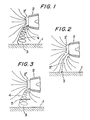
- Fig. 1 is a schematic illustrative view in the vicinity of an engine nacelle for explaining an aerodynamic phenomenon causing drawing of alien bodies,
- Fig. 2 is a schematic ilustrative view similar to Fig. 1 for explaining a critical state prior to generation of a whirlwind,
- Fig. 3 is a schematic illustrated view similar to Fig. 1 and 2 for explaining the phenomenon upon an obstructive body being provided,
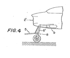
- Fig. 4 is a side view of an embodiment according to this invention.
- Referring to Fig. 1, numeral 4 indicates a whirlwind caused by an engine in operation of an airplane on the ground. Such whirlwind causes whirling-up of alien bodies such as pebbles or the like casually lying scattered on the ground so that the same may be drawing through air-intake 2' into
gas turbine engine 2. Such a phenomenon is well known. - Referring to Fig. 2, upon operation of an engine, a large amount of air is drawn with force through air-intake 2' which is provided at the front face of engine nacelle, i.e.
gas turbine engine 2. The stream lines are formed such as indicated in the figure which show also that air in the vicinity of ground surface 1 is drawn upwardly. However, the velocity of such air flow is small, presence ofstagnation point 3 which is unstable from the view point of energy at a location where stagnation line 3' crosses ground surface 1 can be found. However, with all the presence of such a stagnation point, ascension of alien bodies such as pebbles or the like accompanied by air flow to reach air-intake 2' cannot yet be caused. Such a state of air below the air-intake is considered to be a critical state. And, upon addition of a natural wind having a component of turbulence to an environment as stated above, such a natural wind forms itself to be a trigger, and said critical state gives way to cause a whirlwind 4 as shown in Fig. 1. - Such a natural wind having a component of turbulence, other than a phenomenon which is commonly present in nature, may be caused upon agitation of natural wind with no component of turbulence. And, such an agitation is caused by the presence of any exhaust gas discharged from other airplanes, or any movement of motorcars or individuals passing nearby. And, it can also be caused in such an occasion in which an airplane passes a corner of a building such as a hangar.
- As stated in the foregoing, a whirlwind is caused in such an occasion in which both conditions, that is, (1) a large amount of air is being drawn with force into the air-intake of an aircraft engine, (2) a natural wind having a component of turbulence is present, are satisfied. In an early stage of such whirlwind 4, it is only a small air-eddy, and it extends upwardly and is strengthened afterwards. Such a small air-eddy has not but a small energy. According to wind tunnel experiments, stagnation line 3' is cut loose at a middle portion thereof by means of an obstruc- tuve body such as a metal plate. Upon the stagnation line being cut in such a way, the condition required for the generation of a stagnation point is lost to cause interception of generation of whirlwind 4. The body indicated at 5 in Fig. 3 is such an obstructive body such as stated above.
Obstructive body 5 may have a plate-like configuration such as shown in the figure, but it is not limited to be a plate-like body. And, it is desired that such an obstructive body be located sufficiently below air-intake 2' and extend horizontally from a position slightly rearward of a point which is just below the air-intake to a position which is forward of the same point. - In Fig. 4 is shown an embodiment of this invention. In this embodiment for single engine airplanes,
obstructive body 5 is connected pivotally to retractable landing gear 8' ofalighting gear 8. Upon withdrawal of alightinggear 8 into inside of the airframe such as indicated at the imaginary lines,obstructive body 5 composes door 9 for the alighting gear so that the doorway can be closed byobstructive body 5.
Claims (3)
Applications Claiming Priority (2)
| Application Number | Priority Date | Filing Date | Title |
|---|---|---|---|
| JP16134879A JPS5914613B2 (en) | 1979-12-12 | 1979-12-12 | Aircraft gas turbine engine foreign object inhalation prevention device |
| JP161348/79 | 1979-12-12 |
Publications (2)
| Publication Number | Publication Date |
|---|---|
| EP0030709A1 EP0030709A1 (en) | 1981-06-24 |
| EP0030709B1 true EP0030709B1 (en) | 1985-11-13 |
Family
ID=15733364
Family Applications (1)
| Application Number | Title | Priority Date | Filing Date |
|---|---|---|---|
| EP19800107785 Expired EP0030709B1 (en) | 1979-12-12 | 1980-12-10 | Preventive means against the drawing of alien bodies into aircraft gas turbine engines |
Country Status (3)
| Country | Link |
|---|---|
| EP (1) | EP0030709B1 (en) |
| JP (1) | JPS5914613B2 (en) |
| DE (1) | DE3071236D1 (en) |
Families Citing this family (2)
| Publication number | Priority date | Publication date | Assignee | Title |
|---|---|---|---|---|
| JPH04212378A (en) * | 1990-10-09 | 1992-08-03 | Shiro Yamada | Electrode structural body for high-frequency heating and solidifying device |
| JPH04197269A (en) * | 1990-11-29 | 1992-07-16 | Shiro Yamada | Electrode structural body for high-frequency heating and solidifying |
Family Cites Families (1)
| Publication number | Priority date | Publication date | Assignee | Title |
|---|---|---|---|---|
| GB1167911A (en) * | 1967-01-17 | 1969-10-22 | Rolls Royce | Pod for a Gas Turbine Engine. |
-
1979
- 1979-12-12 JP JP16134879A patent/JPS5914613B2/en not_active Expired
-
1980
- 1980-12-10 EP EP19800107785 patent/EP0030709B1/en not_active Expired
- 1980-12-10 DE DE8080107785T patent/DE3071236D1/en not_active Expired
Also Published As
| Publication number | Publication date |
|---|---|
| EP0030709A1 (en) | 1981-06-24 |
| DE3071236D1 (en) | 1985-12-19 |
| JPS5914613B2 (en) | 1984-04-05 |
| JPS5683522A (en) | 1981-07-08 |
Similar Documents
| Publication | Publication Date | Title |
|---|---|---|
| US5158251A (en) | Aerodynamic surface tip vortex attenuation system | |
| EP3718886B1 (en) | Aircraft having embedded engines | |
| US8152095B2 (en) | Aircraft having a reduced acoustic signature | |
| US6129309A (en) | Aircraft engine apparatus with reduced inlet vortex | |
| RU2516923C2 (en) | Spacecraft afterbody arrangement | |
| US8118265B2 (en) | Devices and methods to improve wing aerodynamics at low airspeeds | |
| US6969028B2 (en) | Scarf nozzle for a jet engine and method of using the same | |
| EP2060769B1 (en) | Thrust reverser | |
| US5779169A (en) | Aircraft engine inlet hot gas and foreign object ingestion reduction and pitch control system | |
| US6616092B1 (en) | Reusable flyback rocket booster and method for recovering same | |
| GB2155413A (en) | A mechanism for improving flow conditions at air inlets for gas turbine engines installed in aircraft | |
| US5934607A (en) | Shock suppression supersonic aircraft | |
| JP3980775B2 (en) | Aircraft wave resistance reduction method | |
| US5496001A (en) | T-38 aircraft modified with an F-5 wing | |
| US4629147A (en) | Over-the-wing propeller | |
| US4934481A (en) | Arrangement for suppressing jet engine noise | |
| EP1413721B1 (en) | Active ground vortex suppression system for an aircraft engine | |
| GB2070139A (en) | Inlet Cowl for Supersonic Aircraft Engine | |
| US4146197A (en) | Boundary layer scoop for the enhancement of Coanda effect flow deflection over a wing/flap surface | |
| US4768737A (en) | Helicopter control system | |
| US3493198A (en) | Aerodynamic landing roll braking of turbojet powered aircraft | |
| EP0030709B1 (en) | Preventive means against the drawing of alien bodies into aircraft gas turbine engines | |
| US3981463A (en) | Overwing thrust reverser | |
| EP2610170A1 (en) | Air drag reduction for an undercarriage with skids of a rotary wing aircraft | |
| US2844337A (en) | Aircraft control arrangement incorporating deflectable surface and boundary layer control jets |
Legal Events
| Date | Code | Title | Description |
|---|---|---|---|
| PUAI | Public reference made under article 153(3) epc to a published international application that has entered the european phase |
Free format text: ORIGINAL CODE: 0009012 |
|
| AK | Designated contracting states |
Designated state(s): DE FR GB IT NL |
|
| 17P | Request for examination filed |
Effective date: 19820223 |
|
| ITF | It: translation for a ep patent filed | ||
| GRAA | (expected) grant |
Free format text: ORIGINAL CODE: 0009210 |
|
| AK | Designated contracting states |
Designated state(s): DE FR GB IT NL |
|
| REF | Corresponds to: |
Ref document number: 3071236 Country of ref document: DE Date of ref document: 19851219 |
|
| ET | Fr: translation filed | ||
| PLBE | No opposition filed within time limit |
Free format text: ORIGINAL CODE: 0009261 |
|
| STAA | Information on the status of an ep patent application or granted ep patent |
Free format text: STATUS: NO OPPOSITION FILED WITHIN TIME LIMIT |
|
| 26N | No opposition filed | ||
| PGFP | Annual fee paid to national office [announced via postgrant information from national office to epo] |
Ref country code: GB Payment date: 19911206 Year of fee payment: 12 |
|
| PGFP | Annual fee paid to national office [announced via postgrant information from national office to epo] |
Ref country code: FR Payment date: 19911227 Year of fee payment: 12 |
|
| ITTA | It: last paid annual fee | ||
| PGFP | Annual fee paid to national office [announced via postgrant information from national office to epo] |
Ref country code: NL Payment date: 19911231 Year of fee payment: 12 |
|
| PGFP | Annual fee paid to national office [announced via postgrant information from national office to epo] |
Ref country code: DE Payment date: 19920228 Year of fee payment: 12 |
|
| PG25 | Lapsed in a contracting state [announced via postgrant information from national office to epo] |
Ref country code: GB Effective date: 19921210 |
|
| PG25 | Lapsed in a contracting state [announced via postgrant information from national office to epo] |
Ref country code: NL Effective date: 19930701 |
|
| GBPC | Gb: european patent ceased through non-payment of renewal fee |
Effective date: 19921210 |
|
| NLV4 | Nl: lapsed or anulled due to non-payment of the annual fee | ||
| PG25 | Lapsed in a contracting state [announced via postgrant information from national office to epo] |
Ref country code: FR Effective date: 19930831 |
|
| PG25 | Lapsed in a contracting state [announced via postgrant information from national office to epo] |
Ref country code: DE Effective date: 19930901 |
|
| REG | Reference to a national code |
Ref country code: FR Ref legal event code: ST |