EP0030340B1 - Apparatus for bending and tempering glass sheets, especially thin sheets - Google Patents
Apparatus for bending and tempering glass sheets, especially thin sheets Download PDFInfo
- Publication number
- EP0030340B1 EP0030340B1 EP80107455A EP80107455A EP0030340B1 EP 0030340 B1 EP0030340 B1 EP 0030340B1 EP 80107455 A EP80107455 A EP 80107455A EP 80107455 A EP80107455 A EP 80107455A EP 0030340 B1 EP0030340 B1 EP 0030340B1
- Authority
- EP
- European Patent Office
- Prior art keywords
- forming
- frame
- tempering
- rolls
- sheets
- Prior art date
- Legal status (The legal status is an assumption and is not a legal conclusion. Google has not performed a legal analysis and makes no representation as to the accuracy of the status listed.)
- Expired
Links
- 239000011521 glass Substances 0.000 claims description 43
- 238000005496 tempering Methods 0.000 claims description 29
- 230000033001 locomotion Effects 0.000 claims description 10
- 238000005452 bending Methods 0.000 claims description 6
- 238000010438 heat treatment Methods 0.000 claims description 6
- 238000004519 manufacturing process Methods 0.000 claims description 4
- 230000000284 resting effect Effects 0.000 claims description 2
- 230000000630 rising effect Effects 0.000 claims description 2
- 230000007423 decrease Effects 0.000 description 6
- 238000000034 method Methods 0.000 description 5
- 238000001816 cooling Methods 0.000 description 3
- 239000005341 toughened glass Substances 0.000 description 3
- 230000003287 optical effect Effects 0.000 description 2
- 238000007664 blowing Methods 0.000 description 1
- 230000000295 complement effect Effects 0.000 description 1
- 238000007599 discharging Methods 0.000 description 1
- 230000001771 impaired effect Effects 0.000 description 1
- 230000001788 irregular Effects 0.000 description 1
- 239000000463 material Substances 0.000 description 1
- 230000033764 rhythmic process Effects 0.000 description 1
- 238000004904 shortening Methods 0.000 description 1
Images


Classifications
-
- C—CHEMISTRY; METALLURGY
- C03—GLASS; MINERAL OR SLAG WOOL
- C03B—MANUFACTURE, SHAPING, OR SUPPLEMENTARY PROCESSES
- C03B27/00—Tempering or quenching glass products
- C03B27/04—Tempering or quenching glass products using gas
- C03B27/044—Tempering or quenching glass products using gas for flat or bent glass sheets being in a horizontal position
- C03B27/0442—Tempering or quenching glass products using gas for flat or bent glass sheets being in a horizontal position for bent glass sheets
- C03B27/0445—Tempering or quenching glass products using gas for flat or bent glass sheets being in a horizontal position for bent glass sheets the quench unit being adapted to the bend of the sheet
-
- C—CHEMISTRY; METALLURGY
- C03—GLASS; MINERAL OR SLAG WOOL
- C03B—MANUFACTURE, SHAPING, OR SUPPLEMENTARY PROCESSES
- C03B23/00—Re-forming shaped glass
- C03B23/02—Re-forming glass sheets
- C03B23/023—Re-forming glass sheets by bending
- C03B23/025—Re-forming glass sheets by bending by gravity
- C03B23/0256—Gravity bending accelerated by applying mechanical forces, e.g. inertia, weights or local forces
-
- C—CHEMISTRY; METALLURGY
- C03—GLASS; MINERAL OR SLAG WOOL
- C03B—MANUFACTURE, SHAPING, OR SUPPLEMENTARY PROCESSES
- C03B23/00—Re-forming shaped glass
- C03B23/02—Re-forming glass sheets
- C03B23/023—Re-forming glass sheets by bending
- C03B23/03—Re-forming glass sheets by bending by press-bending between shaping moulds
-
- C—CHEMISTRY; METALLURGY
- C03—GLASS; MINERAL OR SLAG WOOL
- C03B—MANUFACTURE, SHAPING, OR SUPPLEMENTARY PROCESSES
- C03B35/00—Transporting of glass products during their manufacture, e.g. hot glass lenses, prisms
- C03B35/14—Transporting hot glass sheets or ribbons, e.g. by heat-resistant conveyor belts or bands
- C03B35/16—Transporting hot glass sheets or ribbons, e.g. by heat-resistant conveyor belts or bands by roller conveyors
- C03B35/161—Transporting hot glass sheets or ribbons, e.g. by heat-resistant conveyor belts or bands by roller conveyors specially adapted for bent sheets or ribbons
-
- C—CHEMISTRY; METALLURGY
- C03—GLASS; MINERAL OR SLAG WOOL
- C03B—MANUFACTURE, SHAPING, OR SUPPLEMENTARY PROCESSES
- C03B35/00—Transporting of glass products during their manufacture, e.g. hot glass lenses, prisms
- C03B35/14—Transporting hot glass sheets or ribbons, e.g. by heat-resistant conveyor belts or bands
- C03B35/20—Transporting hot glass sheets or ribbons, e.g. by heat-resistant conveyor belts or bands by gripping tongs or supporting frames
Definitions
- the present invention relates to the production of curved and tempered (toughened) glass, especially thin sheets.
- Such products are frequently used as windows for vehicles in general, more especially for automobiles.
- This application requires that the windows be accurately made, both as regards the required dimensions and tolerances of curvature, as well as the configuration to correspond to the general shape of the vehicle body.
- tempered glass sheets especially those used in the automobile industry, can be manufactured by horizontal machines which permit high outputs.
- each glass sheet is conveyed horizontally by a roller conveyor during the consecutive heating, forming (if required) and tempering phases.
- the piece leaves the forming press and passes on to the tempering zone via a roller conveyor.
- the thinner is the glass sheet the greater is the risk of deformation, since, whilst it is true that the weight and inertia decrease in proportion with the decrease in thickness of the glass sheet, it is also true that resistance to deformation decreases more or less with the cube of the thickness of the glass sheet.
- the Applicant makes use of a known process on an apparatus in which the conveying of the sheet takes place through rolls in all their working phases and precisely through roll sets 'formed by a fixed and an interchangeable part (which was already been provided only in the U.S.A. Patent 3.338.695 Ritter).
- Such rolls are indeed suitable for supporting and conveying the glass sheet from the tempering zone to the forming zone, conforming to the form of the sheet to be bent, but they are constrained to the conveying plane at their ends (see 92').
- the forming ring (145, 146) is constrained, in its downward motion, by the presence of the supporting axles of the rolls outside said ring.
- sheets can be produced whose bending is greater than in past times, as the supporting ring can fall more, with relation to the plane of the rolls, than it was possible before (see U.S.A. Patent 3.338.695 Ritter).
- the Applicant has devised a bending and tempering appratus for the glass piece which is still highly plastic when it emerges from the furnace, in order to safeguard both the shape within the required tolerances, and the optical properties of the glass as well as its desired degree of toughness and which enables the production of strongly bent sheets with different configurations and dimensions.
- the present invention relates effectively to an apparatus for bending and tempering glass sheets, and especially thin sheets comprising
- connection means are also provided between ring and frame and the latter rests on traverse small bases resting in turn on two vertically movable tracks and so that it can, by rising, pass above the rolls, and moreover in that besides the supporting and conveying means, other similar means overlying the former ones are provided and in the upper tempering nozzle section a passage way or chamber is suitably designed to allow the frame and forming ring, as well as their horizontal conveying means to pass through it in the horizontal return direction.
- the longitudinal direction is considered to be that parallel to the direction of movement of the glass sheet, the cross direction, the one perpendicular to it, and the vertical one, the one normally taken as being vertical.
- the glass sheet V which has been previously heated to the softening point in furnace F is conveyed by rolls 1 in the direction of arrow W until it reaches frame 2, whereupon it is rested on other rolls 5.
- Said frame 2 can be made of any suitable material provided it has good resistance to heat and low specific weight.
- the frame supports in turn (Fig. 3), the actua) forming ring 3.
- connections 4 between forming ring 3 and frame 2 are designed so as to permit all the . necessary adjustments required for setting up the forming phase of glass sheet V.
- frame 2 passes beyond conveyor rolls 5 and is raised upwards, thereby permitting (with the assistance, if required of male member 6 located above) glass sheet V to be formed according to the desired degree of curvature.
- the forming frame 2 is rested, in actual practice, (Fig. 2) on two cross blocks 7 which, in turn, rest upon wo vertically movable tracks 12 which impart a rise and fall movement to frame 2.
- Said vertical movement is preferably carried out through a device 8 consisting of a rotating screw with moving screw nut.
- the frame 2 including integral forming ring 3 and glass sheet V which is by now formed but still in the plastic state, is coupled to a pin 9 of a tooth 10 which, when moved by a chain 11, causes frame 2 to travel on another pair of fixed tracks 12a.
- Chain movement 11 is powered by electric stepping motors (not shown in the Figure).
- Frame 2 moves along tracks 12a and passes nozzles S of the tempering zone, after which, the gase separating the forming and tempering zones, is automatically lowered.
- the speed at which frame 2 travels under nozzles S of the tempering zone depends on the temperature of glass sheets V, on the air flow rate of nozzles S, and on the required degree of tempering.
- Air blowing pressure in the tempering zone is around 1500 to 2000 mm H 2 0, while the rate of travel under nozzles S is about 0.07 to 0.15 m/s.
- Glass sheet V therefore remains securely attached to frame 2 and forming ring 3; hence it is submitted in a most original way to an accurate vibration-free movement during the delicate holding phase of the mould at high temperature.
- glass sheet V is hardened and consolidated through the heat treatment into the previously assumed shape.
- frame 2 loaded with glass sheet V travels towards the glass sheet discharge zone Z.
- frame 2 is lowered under the level of conveyor rolls 5a through vertical moving device 8a which is similar to device 8 in the forming zone C.
- the as-formed and tempered glass sheet V is released, during the downwards movement of frame 2, on to the rolls 5a.
- Average duration of the above described work cycle is from 4 to 5 seconds; hence it can well meet the required output rhythm and productivity.
- Frame 2 after discharging the glass sheet, is then raised automatically until reaching the same level as track 12' ready for its return to the inlet of furnace F.
- a passageway 14 in the upper nozzle section S of the tempering zone allows the frame 2 to pass through during its return travel.
- Air supply pipes T are adequately dimensioned in this zone so as not to allow the amount and pressure of air during the tempering phase to decrease.
- the return traversing system for frame 2 is identical to that described previously for the forward traverse, with analogous members, that is, pin 9', tooth 10' and chain 11'.
- male member 6 is provided with a horizontal traversing device which traverses it to position 6a thereby retracting it from the path of said frame 2 when the latter is on its way to the inlet of furnace F.
- the same device traverses male member 6 back to its vertical position on frame 2 ready for the forming operation.
- the latter conveyor rolls 5 (Fig. 3) are likewise arranged in a special way, that is, in distinct sections, a central section B of constant length, and two side sections B' whose length varies according to requirements.
Landscapes
- Chemical & Material Sciences (AREA)
- Engineering & Computer Science (AREA)
- Materials Engineering (AREA)
- Organic Chemistry (AREA)
- Mechanical Engineering (AREA)
- Physics & Mathematics (AREA)
- Thermal Sciences (AREA)
- Re-Forming, After-Treatment, Cutting And Transporting Of Glass Products (AREA)
Description
- The present invention relates to the production of curved and tempered (toughened) glass, especially thin sheets.
- Such products are frequently used as windows for vehicles in general, more especially for automobiles.
- This application requires that the windows be accurately made, both as regards the required dimensions and tolerances of curvature, as well as the configuration to correspond to the general shape of the vehicle body.
- Moreover, it is necessary that the visibility through such windows should not be impaired by optical distortions or by flaws in the glass. As is well known, tempered glass sheets, especially those used in the automobile industry, can be manufactured by horizontal machines which permit high outputs.
- In these machines, each glass sheet is conveyed horizontally by a roller conveyor during the consecutive heating, forming (if required) and tempering phases.
- In the case of curved glass sheets, these sheets are collected at the output of a forming press which forms them into the required shape.
- After the forming operation, the piece leaves the forming press and passes on to the tempering zone via a roller conveyor.
- In order for a piece to be efficiently tempered, it must still retain a certain degree of plasticity.
- This plasticity, which is an essential conditions for tempering, inevitably leads to deformation of the shape previously assumed by the glass when submitted to treatment in the forming press.
- Causes of deformation are essentially as follows:
- a) the glass' own weight
- b) inertia of the glass sheet
- c) action of the first blasts of hot air in the tempering zone
- d) any asymmetrical cooling between the upper and lower sides of the glass sheet.
- It should be noted that the thinner is the glass sheet, the greater is the risk of deformation, since, whilst it is true that the weight and inertia decrease in proportion with the decrease in thickness of the glass sheet, it is also true that resistance to deformation decreases more or less with the cube of the thickness of the glass sheet.
- The deformation due to the hot blast of air in tempering is also very marked.
- During recent years, much commercial importance has been placed on thinner and thinner curved tempered glass sheets, with thicknesses passing from 5-6.5 mm down to 2.5-4 mm.
- Consequently, a bending process such as that described above in which the piece travels on a roller conveyor, is particularly affected by the decrease in thickness since the resistance to deformation decreases more or less with the cube of the thickness.
- The increase of blasts of hot air for tempering which is necessary on account of the higher temperature gradient required by the thinner glass sheets contributes, in turn, to the lower structural resistance, thereby making it difficult to control the shape of the product which, after forming, is still in the plastic state.
- From the prior art are well known many processes for bending and tempering thin glass sheets, among which are particularly important the patents:
- -FR 1.474.251 (Libbey-Owens-Ford)
- - U.S.A. 3.684.473 (Ritter), disclosing an apparatus according to the prior art portion of claim 1
- - FR 2.046.790 (Permaglass)
- 1) In some known processes one takes advantage of apparatus in which the glass sheet, under the tempering blowers, is supported by a forming ring, and the conveying of the sheet takes place on a gaseous bed: (see Patents FR 2.046.790 Permaglass-U.S.A. 3.607.200 McMaster and DE 2.400.296 P.P.G.).
- 2) In other processes instead one takes advantage of apparatus in which the glass sheet is conveyed on rolls: (see Patents FR 1.474.251 Libbey-Owens-Ford-U.S.A. 2.684.473 Ritter-LU 65.146 Libbey-Owens-Ford-U.S.A. 3.338.695 Ritter-U.S.A. 4.092.141 Frank. '
- The Applicant makes use of a known process on an apparatus in which the conveying of the sheet takes place through rolls in all their working phases and precisely through roll sets 'formed by a fixed and an interchangeable part (which was already been provided only in the U.S.A. Patent 3.338.695 Ritter).
- In the latter patent the rolls (148, 149) are already provided side by side in two dimensions with complementary widths utilizable according to the glass sheet to be produced.
- Such rolls are indeed suitable for supporting and conveying the glass sheet from the tempering zone to the forming zone, conforming to the form of the sheet to be bent, but they are constrained to the conveying plane at their ends (see 92').
- Therefore the forming ring (145, 146) is constrained, in its downward motion, by the presence of the supporting axles of the rolls outside said ring.
- On the contrary, according to the present invention there are provided free outer roll ends, so that the forming
ring 3 can rise and fall with the glass sheet, without any constraint. - Nevertheless, the outer rolls (B') are still interchangeable according to the dimension of the sheet to be bent, as in the U.S.A. Patent 3.338.695 Ritter.
- So, with the apparatus according to the invention sheets can be produced whose bending is greater than in past times, as the supporting ring can fall more, with relation to the plane of the rolls, than it was possible before (see U.S.A. Patent 3.338.695 Ritter).
- The release of the forming and supporting ring of the glass sheet from the rolls makes it possible for said ring to perform in the apparatus a continuous movement for many working cycles shortening the working times.
- Hence the Applicant has devised a bending and tempering appratus for the glass piece which is still highly plastic when it emerges from the furnace, in order to safeguard both the shape within the required tolerances, and the optical properties of the glass as well as its desired degree of toughness and which enables the production of strongly bent sheets with different configurations and dimensions.
- The present invention relates effectively to an apparatus for bending and tempering glass sheets, and especially thin sheets comprising
- a) a horizontal furnace for heating the glass up to its softening temperature,
- b) means for forming the sheets,
- c) tempering nozzles,
- d) means for supporting and conveying the sheet in the horizontal direction, these means consisting in the heating phase of rolls, in the forming and in discharge zones of further rolls and during the forming and tempering phases of a ring supported by a special frame which contains it,
- e) means for supporting and conveying the frame with integral forming ring horizontally through the consecutive phases of the work cycle, and moreover
- f) means provided for causing a vertical rise and fall movement of the frame both in the forming zone and in the sheet discharge zone, the latter following the tempering zone,
- A suitable embodiment of the invention is characterized in that connection means are also provided between ring and frame and the latter rests on traverse small bases resting in turn on two vertically movable tracks and so that it can, by rising, pass above the rolls, and moreover in that besides the supporting and conveying means, other similar means overlying the former ones are provided and in the upper tempering nozzle section a passage way or chamber is suitably designed to allow the frame and forming ring, as well as their horizontal conveying means to pass through it in the horizontal return direction.
- The accompanying drawings, which are to be considered as an explication of the principles of the invention and are not intended to limit it, illustrate a preferred embodiment of the apparatus in accordance with the invention.
- In the drawings:
- Figure 1 is an assembly view of the apparatus;
- Figure 2 is a cross sectional view of said apparatus taken along the lines II-II of Figure 1;
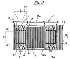
- Figure 3 is a plan view of the apparatus itself.
- In the following description, the longitudinal direction is considered to be that parallel to the direction of movement of the glass sheet, the cross direction, the one perpendicular to it, and the vertical one, the one normally taken as being vertical.
- As can be seen from the drawing (Fig. 1), the glass sheet V, which has been previously heated to the softening point in furnace F is conveyed by rolls 1 in the direction of arrow W until it reaches frame 2, whereupon it is rested on
other rolls 5. - Said frame 2 can be made of any suitable material provided it has good resistance to heat and low specific weight.
- The frame supports, in turn (Fig. 3), the actua) forming
ring 3. - The
connections 4 between formingring 3 and frame 2 are designed so as to permit all the . necessary adjustments required for setting up the forming phase of glass sheet V. - Once the glass sheet V is placed on the forming
ring 3, frame 2 passes beyondconveyor rolls 5 and is raised upwards, thereby permitting (with the assistance, if required of male member 6 located above) glass sheet V to be formed according to the desired degree of curvature. - The forming frame 2 is rested, in actual practice, (Fig. 2) on two
cross blocks 7 which, in turn, rest upon wo verticallymovable tracks 12 which impart a rise and fall movement to frame 2. - Said vertical movement is preferably carried out through a
device 8 consisting of a rotating screw with moving screw nut. - After the forming phase, the frame 2, including integral forming
ring 3 and glass sheet V which is by now formed but still in the plastic state, is coupled to a pin 9 of atooth 10 which, when moved by achain 11, causes frame 2 to travel on another pair offixed tracks 12a. -
Chain movement 11 is powered by electric stepping motors (not shown in the Figure). - Frame 2 moves along
tracks 12a and passes nozzles S of the tempering zone, after which, the gase separating the forming and tempering zones, is automatically lowered. - The speed at which frame 2 travels under nozzles S of the tempering zone, depends on the temperature of glass sheets V, on the air flow rate of nozzles S, and on the required degree of tempering.
- Air blowing pressure in the tempering zone is around 1500 to 2000 mm H20, while the rate of travel under nozzles S is about 0.07 to 0.15 m/s.
- Glass sheet V therefore remains securely attached to frame 2 and forming
ring 3; hence it is submitted in a most original way to an accurate vibration-free movement during the delicate holding phase of the mould at high temperature. - In this way, the action of the aerodynamic forces during tempering and the less adequate holding means, such as the conveyor rolls, are prevented from causing irregular and unexpected deformations, or at least deformations difficult to control.
- As a result, glass sheet V is hardened and consolidated through the heat treatment into the previously assumed shape.
- After leaving nozzles S of the tempering zone, frame 2 loaded with glass sheet V travels towards the glass sheet discharge zone Z.
- When the cooling nozzles Sa are reached, frame 2 is lowered under the level of conveyor rolls 5a through vertical moving
device 8a which is similar todevice 8 in the forming zone C. - The as-formed and tempered glass sheet V is released, during the downwards movement of frame 2, on to the
rolls 5a. - These latter items are arranged to deliver glass sheet V to
other rolls 13 on which it is conveyed through cooling nozzles section Sa. - Finally the finished product is discharged from the machine.
- Average duration of the above described work cycle is from 4 to 5 seconds; hence it can well meet the required output rhythm and productivity.
- Frame 2, after discharging the glass sheet, is then raised automatically until reaching the same level as track 12' ready for its return to the inlet of furnace F.
- A
passageway 14 in the upper nozzle section S of the tempering zone allows the frame 2 to pass through during its return travel. - Air supply pipes T are adequately dimensioned in this zone so as not to allow the amount and pressure of air during the tempering phase to decrease.
- The return traversing system for frame 2 is identical to that described previously for the forward traverse, with analogous members, that is, pin 9', tooth 10' and chain 11'.
- When frame 2 reaches the inlet of furnace F it is automatically lowered down to the lower level, that of conveyor rolls 5, ready for the next work cycle.
- In order to allow lowering of frame 2 into the loading position, male member 6 is provided with a horizontal traversing device which traverses it to position 6a thereby retracting it from the path of said frame 2 when the latter is on its way to the inlet of furnace F.
- The same device traverses male member 6 back to its vertical position on frame 2 ready for the forming operation.
- When frame 2 is positioned ready to pick up glass sheet V it is actually (Fig. 1) under conveyor rolls 5.
- The latter conveyor rolls 5 (Fig. 3) are likewise arranged in a special way, that is, in distinct sections, a central section B of constant length, and two side sections B' whose length varies according to requirements.
characterized in that the rolls for conveying the glass sheet in the horizontal direction provided in the forming and discharge zones consist each of a central section of constant length, and two cantilevered side sections whose length can be modified to suit production requirements, that is to say, they can be adapted to the required glass sheet dimensions.
Claims (3)
characterized in that the rolls (5 and 5a) for conveying the glass sheet in the horizontal direction provided in the forming and discharge zones consist each of a central section (B) of constant length, and two cantilevered side sections (B') whose length can be modified to suit production requirements, that is to say, they can be adapted to the required glass sheet dimensions.
Applications Claiming Priority (2)
| Application Number | Priority Date | Filing Date | Title |
|---|---|---|---|
| IT7927967A IT1209156B (en) | 1979-12-07 | 1979-12-07 | PROCEDURE AND EQUIPMENT FOR CURVING AND TEMPERING GLASS SHEETS, PARTICULARLY THIN THICK. |
| IT2796779 | 1979-12-07 |
Publications (2)
| Publication Number | Publication Date |
|---|---|
| EP0030340A1 EP0030340A1 (en) | 1981-06-17 |
| EP0030340B1 true EP0030340B1 (en) | 1984-02-15 |
Family
ID=11222699
Family Applications (1)
| Application Number | Title | Priority Date | Filing Date |
|---|---|---|---|
| EP80107455A Expired EP0030340B1 (en) | 1979-12-07 | 1980-11-28 | Apparatus for bending and tempering glass sheets, especially thin sheets |
Country Status (5)
| Country | Link |
|---|---|
| US (1) | US4339259A (en) |
| EP (1) | EP0030340B1 (en) |
| DE (1) | DE3066646D1 (en) |
| ES (1) | ES8202320A1 (en) |
| IT (1) | IT1209156B (en) |
Families Citing this family (15)
| Publication number | Priority date | Publication date | Assignee | Title |
|---|---|---|---|---|
| IT1138266B (en) * | 1981-04-06 | 1986-09-17 | Siv Soc Italiana Vetro | EQUIPMENT FOR CURVING AND TEMPERA OF THIN THICK GLASS SHEETS |
| US4518410A (en) * | 1983-05-09 | 1985-05-21 | Ppg Industries, Inc. | Storing bending molds |
| EP0354001B1 (en) * | 1988-08-03 | 1993-03-31 | Nippon Sheet Glass Co. Ltd. | Apparatus for bending glass sheet |
| JPH02296741A (en) * | 1989-05-11 | 1990-12-07 | Nippon Sheet Glass Co Ltd | Bend molding device for sheet glass |
| US5004492A (en) * | 1989-08-29 | 1991-04-02 | Libbey-Owens-Ford Co. | Glass sheet conveying and bending apparatus |
| DE4020708A1 (en) * | 1990-06-29 | 1992-01-09 | Ver Glaswerke Gmbh | METHOD AND DEVICE FOR PRODUCING CURVED AND TEMPERED GLASS PANELS |
| DE4208219C1 (en) * | 1992-03-14 | 1993-05-06 | Vegla Vereinigte Glaswerke Gmbh, 5100 Aachen, De | |
| GB9407610D0 (en) * | 1994-04-15 | 1994-06-08 | Pilkington Glass Ltd | Bending and tempering glass sheets |
| IT1312035B1 (en) * | 1999-03-30 | 2002-04-04 | Techint Spa | PLANT FOR THE PRODUCTION OF GLASS PANELS, DEVICE FOR THE POSITIONING OF A GLASS SHEET IN CORRESPONDENCE WITH A |
| FR2821285B1 (en) * | 2001-02-23 | 2003-11-28 | Saint Gobain Seva | DEVICE FOR BLOWING A FLUID ON AT LEAST ONE SIDE OF A THIN ELEMENT, AND ASSOCIATED BLOW UNIT |
| ATE348080T1 (en) * | 2001-03-23 | 2007-01-15 | Glaverbel | METHOD AND DEVICE FOR HEATING GLASS PANELS IN A FURNACE |
| BE1014065A3 (en) * | 2001-03-23 | 2003-03-04 | Glaverbel | Heating of glass sheets on a roller conveyor in a furnace by radiation and forced convection with the injection of hot gas |
| US20110247367A1 (en) * | 2010-04-08 | 2011-10-13 | Glasstech, Inc. | Press bending station and method for bending heated glass sheets |
| CN107840565B (en) * | 2017-11-29 | 2024-11-29 | 上海北玻玻璃技术工业有限公司 | Production equipment and production method for horizontal roller way type reverse bending toughened glass |
| CN113149413B (en) * | 2021-05-26 | 2022-09-06 | 郑州福耀玻璃有限公司 | Vertical furnace production line for automobile glass |
Family Cites Families (9)
| Publication number | Priority date | Publication date | Assignee | Title |
|---|---|---|---|---|
| US3338695A (en) * | 1962-09-14 | 1967-08-29 | Libbey Owens Ford Glass Co | Method and apparatus for press bending and tempering glass sheets |
| US3294516A (en) * | 1964-09-02 | 1966-12-27 | Libbey Owens Ford Glass Co | Apparatus for press bending glass sheets |
| US3607200A (en) * | 1967-12-18 | 1971-09-21 | Permaglass | Apparatus for conveying glass sheets through adjacent bending and tempering stations |
| US3573889A (en) * | 1969-06-16 | 1971-04-06 | Permaglass | Method for shaping,tempering and laminating glass sheets |
| US3684473A (en) * | 1970-08-28 | 1972-08-15 | Libbey Owens Ford Co | Bending and tempering glass sheets |
| US3734706A (en) * | 1971-04-16 | 1973-05-22 | Libbey Owens Ford Co | Producing bent tempered glass sheets |
| US3846104A (en) * | 1973-01-10 | 1974-11-05 | Ppg Industries Inc | Handling glass sheets for shaping and cooling |
| US4092141A (en) * | 1977-01-03 | 1978-05-30 | Ppg Industries, Inc. | Method and apparatus for handling glass sheets for shaping and cooling |
| US4204853A (en) * | 1978-11-13 | 1980-05-27 | Ppg Industries, Inc. | Glass sheet alignment means and method of using |
-
1979
- 1979-12-07 IT IT7927967A patent/IT1209156B/en active
-
1980
- 1980-11-28 EP EP80107455A patent/EP0030340B1/en not_active Expired
- 1980-11-28 DE DE8080107455T patent/DE3066646D1/en not_active Expired
- 1980-12-01 US US06/211,721 patent/US4339259A/en not_active Expired - Lifetime
- 1980-12-05 ES ES497490A patent/ES8202320A1/en not_active Expired
Also Published As
| Publication number | Publication date |
|---|---|
| DE3066646D1 (en) | 1984-03-22 |
| ES497490A0 (en) | 1982-01-16 |
| EP0030340A1 (en) | 1981-06-17 |
| IT1209156B (en) | 1989-07-10 |
| IT7927967A0 (en) | 1979-12-07 |
| ES8202320A1 (en) | 1982-01-16 |
| US4339259A (en) | 1982-07-13 |
Similar Documents
| Publication | Publication Date | Title |
|---|---|---|
| US4285715A (en) | Cycle of mold movement while press bending glass sheets | |
| US4339259A (en) | Process and apparatus for bending and tempering glass sheets, especially thin sheets | |
| US4883526A (en) | Method and apparatus for shaping and conveying glass sheets | |
| US4197108A (en) | Slotted glass sheet shaping mold | |
| US4277276A (en) | Method and apparatus for shaping glass sheets using deformable vacuum mold | |
| US4272274A (en) | Slotted glass sheet shaping mold | |
| CA1120725A (en) | Apparatus for bending and tempering glass | |
| FI58623B (en) | ANORDNING FOER BOEJNING AV VAERMEUPPMJUKADE GLASSKIVOR | |
| US4447252A (en) | Apparatus for curving and tempering or heat toughening thin glass sheets | |
| US5336288A (en) | Apparatus for the manufacture of sheets of glass having a complex shape | |
| JP3559052B2 (en) | Glass sheet bending method and glass sheet bending apparatus | |
| US4221580A (en) | Glass sheet vacuum molding apparatus with uniform release means | |
| US4252552A (en) | Shaping glass sheets using molds of different shapes | |
| US3992181A (en) | Shaping glass sheets | |
| US4767434A (en) | Horizontal press bending pickup and delivery system | |
| US4233049A (en) | Method and apparatus for shaping glass sheets by drop forming | |
| US4218232A (en) | Method of shaping moving sheets on roll forming apparatus | |
| JPH07291646A (en) | Bending and heating equipment for sheet glass | |
| US4368065A (en) | Method and apparatus to remove bent, tempered glass sheets from a cooling station | |
| US4298368A (en) | Delivering and aligning glass sheets in a bending station | |
| EP0523017B1 (en) | Apparatus and process for the manufacture of sheets of glass having a complex shape | |
| EP0103983A1 (en) | Apparatus and method for locally heating conveyed glass sheets | |
| US3834885A (en) | Method of conveying glass sheets through a furnace | |
| US4430111A (en) | Method and apparatus to remove sharply bent, tempered glass sheets from a cooling station | |
| US4199341A (en) | Glass lift mechanism for and method of press bending glass sheets |
Legal Events
| Date | Code | Title | Description |
|---|---|---|---|
| PUAI | Public reference made under article 153(3) epc to a published international application that has entered the european phase |
Free format text: ORIGINAL CODE: 0009012 |
|
| AK | Designated contracting states |
Kind code of ref document: A1 Designated state(s): BE DE FR GB LU NL Designated state(s): BE DE FR GB LU NL |
|
| 17P | Request for examination filed |
Effective date: 19810723 |
|
| GRAA | (expected) grant |
Free format text: ORIGINAL CODE: 0009210 |
|
| AK | Designated contracting states |
Kind code of ref document: B1 Designated state(s): BE DE FR GB LU NL Designated state(s): BE DE FR GB LU NL |
|
| REF | Corresponds to: |
Ref document number: 3066646 Country of ref document: DE Date of ref document: 19840322 |
|
| ET | Fr: translation filed | ||
| PLBE | No opposition filed within time limit |
Free format text: ORIGINAL CODE: 0009261 |
|
| STAA | Information on the status of an ep patent application or granted ep patent |
Free format text: STATUS: NO OPPOSITION FILED WITHIN TIME LIMIT |
|
| 26N | No opposition filed | ||
| EPTA | Lu: last paid annual fee | ||
| PGFP | Annual fee paid to national office [announced via postgrant information from national office to epo] |
Ref country code: FR Payment date: 19951024 Year of fee payment: 16 |
|
| PGFP | Annual fee paid to national office [announced via postgrant information from national office to epo] |
Ref country code: LU Payment date: 19951101 Year of fee payment: 16 |
|
| PGFP | Annual fee paid to national office [announced via postgrant information from national office to epo] |
Ref country code: BE Payment date: 19951110 Year of fee payment: 16 |
|
| PGFP | Annual fee paid to national office [announced via postgrant information from national office to epo] |
Ref country code: GB Payment date: 19951121 Year of fee payment: 16 |
|
| PGFP | Annual fee paid to national office [announced via postgrant information from national office to epo] |
Ref country code: NL Payment date: 19951130 Year of fee payment: 16 |
|
| PGFP | Annual fee paid to national office [announced via postgrant information from national office to epo] |
Ref country code: DE Payment date: 19951229 Year of fee payment: 16 |
|
| PG25 | Lapsed in a contracting state [announced via postgrant information from national office to epo] |
Ref country code: LU Free format text: LAPSE BECAUSE OF NON-PAYMENT OF DUE FEES Effective date: 19961128 Ref country code: GB Effective date: 19961128 |
|
| PG25 | Lapsed in a contracting state [announced via postgrant information from national office to epo] |
Ref country code: BE Effective date: 19961130 |
|
| BERE | Be: lapsed |
Owner name: SOCIETA ITALIANA VETRO SIV S.P.A. Effective date: 19961130 |
|
| PG25 | Lapsed in a contracting state [announced via postgrant information from national office to epo] |
Ref country code: NL Effective date: 19970601 |
|
| GBPC | Gb: european patent ceased through non-payment of renewal fee |
Effective date: 19961128 |
|
| PG25 | Lapsed in a contracting state [announced via postgrant information from national office to epo] |
Ref country code: FR Effective date: 19970731 |
|
| NLV4 | Nl: lapsed or anulled due to non-payment of the annual fee |
Effective date: 19970601 |
|
| PG25 | Lapsed in a contracting state [announced via postgrant information from national office to epo] |
Ref country code: DE Effective date: 19970801 |
|
| REG | Reference to a national code |
Ref country code: FR Ref legal event code: ST |