EP0030144B1 - Apparatus for minimising the effect of concentrated high density material outside a small scan circle in computed tomography - Google Patents
Apparatus for minimising the effect of concentrated high density material outside a small scan circle in computed tomography Download PDFInfo
- Publication number
- EP0030144B1 EP0030144B1 EP80304291A EP80304291A EP0030144B1 EP 0030144 B1 EP0030144 B1 EP 0030144B1 EP 80304291 A EP80304291 A EP 80304291A EP 80304291 A EP80304291 A EP 80304291A EP 0030144 B1 EP0030144 B1 EP 0030144B1
- Authority
- EP
- European Patent Office
- Prior art keywords
- scan circle
- radiation
- source
- detectors
- circle
- Prior art date
- Legal status (The legal status is an assumption and is not a legal conclusion. Google has not performed a legal analysis and makes no representation as to the accuracy of the status listed.)
- Expired
Links
Images



Classifications
-
- A—HUMAN NECESSITIES
- A61—MEDICAL OR VETERINARY SCIENCE; HYGIENE
- A61B—DIAGNOSIS; SURGERY; IDENTIFICATION
- A61B6/00—Apparatus or devices for radiation diagnosis; Apparatus or devices for radiation diagnosis combined with radiation therapy equipment
- A61B6/48—Diagnostic techniques
- A61B6/483—Diagnostic techniques involving scattered radiation
-
- A—HUMAN NECESSITIES
- A61—MEDICAL OR VETERINARY SCIENCE; HYGIENE
- A61B—DIAGNOSIS; SURGERY; IDENTIFICATION
- A61B6/00—Apparatus or devices for radiation diagnosis; Apparatus or devices for radiation diagnosis combined with radiation therapy equipment
- A61B6/02—Arrangements for diagnosis sequentially in different planes; Stereoscopic radiation diagnosis
- A61B6/03—Computed tomography [CT]
- A61B6/032—Transmission computed tomography [CT]
-
- A—HUMAN NECESSITIES
- A61—MEDICAL OR VETERINARY SCIENCE; HYGIENE
- A61B—DIAGNOSIS; SURGERY; IDENTIFICATION
- A61B6/00—Apparatus or devices for radiation diagnosis; Apparatus or devices for radiation diagnosis combined with radiation therapy equipment
- A61B6/42—Arrangements for detecting radiation specially adapted for radiation diagnosis
- A61B6/4275—Arrangements for detecting radiation specially adapted for radiation diagnosis using a detector unit almost surrounding the patient, e.g. more than 180°
-
- G—PHYSICS
- G06—COMPUTING OR CALCULATING; COUNTING
- G06T—IMAGE DATA PROCESSING OR GENERATION, IN GENERAL
- G06T12/00—Tomographic reconstruction from projections
- G06T12/10—Image preprocessing, e.g. calibration, positioning of sources or scatter correction
-
- G—PHYSICS
- G06—COMPUTING OR CALCULATING; COUNTING
- G06T—IMAGE DATA PROCESSING OR GENERATION, IN GENERAL
- G06T2211/00—Image generation
- G06T2211/40—Computed tomography
- G06T2211/421—Filtered back projection [FBP]
-
- Y—GENERAL TAGGING OF NEW TECHNOLOGICAL DEVELOPMENTS; GENERAL TAGGING OF CROSS-SECTIONAL TECHNOLOGIES SPANNING OVER SEVERAL SECTIONS OF THE IPC; TECHNICAL SUBJECTS COVERED BY FORMER USPC CROSS-REFERENCE ART COLLECTIONS [XRACs] AND DIGESTS
- Y10—TECHNICAL SUBJECTS COVERED BY FORMER USPC
- Y10S—TECHNICAL SUBJECTS COVERED BY FORMER USPC CROSS-REFERENCE ART COLLECTIONS [XRACs] AND DIGESTS
- Y10S378/00—X-ray or gamma ray systems or devices
- Y10S378/901—Computer tomography program or processor
Definitions
- This invention relates to an apparatus for eliminating or at least substantially minimizing a streaking artifact observed in high resolution computed tomography (CT) scans of a small area of interest such as the spine in the vicinity of bones lying within a scan, but outside the imaged region.
- CT computed tomography
- Fig. 1 illustrates the mechanism of the artifact.
- Point V represents a detector 20, one of a plurality of detectors (two represented) 9 (see Fig. 8) disposed equiangularly about detector circle 100.
- the position of detector 20 is defined by its angular displacement ⁇ from the normal, represented by centerline 12 emanating from point U which represents detector 30.
- Points P1 and P2 located on the perimeter of circle 104 represent origins of the source of artifacts viewed by detector 20. These two points are disposed along center line 12 which intersects isocenter 0 of circle 104. From the perspective of detector 20, point P1 is on the far side of isocenter 0 while point P2 is on the near side thereof.
- the data line AB is normal to central ray CR which intersects point V and isocenter 0.
- Fig. 2 shows the projection of information from points P1, 0, and P2 onto the data line AB.
- Source width, source motion, and detector aperture combine to produce an effective point spread function (PSF) for each of the three data points P1, 0, and P2.
- the three PSFs are shown centered on P1', 0, and P2', respectively.
- the full width at half maximum (FWHM), i.e. the width of the projection function at half its amplitude, is indicated on Fig. 2. Since the points are separated by a distance greater than the FWHM, they cannot blend into a uniform distribution.
- FWHM full width at half maximum
- point P1 the view from detector 30 produces a backprojected ray along line 12 through the isocenter 0.
- the adjacent view of point P1 from detector 20 produces a backprojected ray along line 14.
- S F the distance indicated on Fig. 2.
- point P2 indicates that its corresponding rays will be separated by a distance S, as indicated on Fig. 2.
- Fig. 3 shows the effect of backprojecting beams of finite width W about a point 120 representing the origin of an artifact.
- variable width of the low pass filter can be determined.
- Fig. 4 illustrates a small scan circle 10 shown within body section 16 disposed within detector circle 100.
- the area of diagnostic significance is fully contained within the region defined by small scan circle 10.
- the small scan circle 10 includes therewithin a section of the patient's spinal cord 18 and spinal column 22.
- bone sections 24 Located well outside the scan circle 10 are bone sections 24, the sources of the artifact.
- detector circle 100 which surrounds body section 16 and hence bone sections 24, the locations about detector circle 100 to which portions of bone sections 24 would project are determined.
- the horizontal is denoted 0° and angular displacements therefrom in counterclockwise rotation are indicated as negative. This convention is consistently followed in the diagrammatical illustrations of Figs. 5-7.
- Fig. 5 illustrates where the shoulder attenuation values appear in the projection data based upon the example of Fig. 4.
- the shoulder located nearest the detectors first appears (as indicated on the left column) over the detector view angle range 23 to 10 degrees and disappears (as indicated on the right column) over the range 1 to -13 degrees.
- the distant shoulder first appears on the right side of the projection data between 21 and 10 degrees and disappears between -22 and -34 degrees.
- a similar situation occurs 180 degrees around the scan circle with the nearest shoulder appearing between -167 and -181 degrees and disappearing between -190 and -203 degrees.
- the distant shoulder again appears on the right side between -146 and -158 degrees and disappears between -190 and -201 degrees.
- an equal weighted filter of width 2.75 mm (based on calculations for S N and equivalent to an 11 point filter for sample rate of four samples per millimeter at the centre of the scan circle) is sufficient to widen the discontinuities, i.e. effectively increase the critical radius such that they do not contribute to a streaking effect in the reconstructed image.
- a filter of width 1.75 mm (based on calculations for S F and equivalent to a 7 point filter for data sampled at four samples per millimeter) is sufficient to cancel its effects. It is therefore only necessary to decide where in the projection data this filtering should take place.
- Fig. 4 shows the geometry that must be considered to determine at what view angles the shoulder projections appear. Once these angles have been determined, the regions in which the shoulder projections appear in the projection data can be outlined as shown in Fig. 5.
- Filter I Filter the regions with a filter which processes only those areas within the projections which contain the shoulder projections, one width for nearby shoulders, the other width for distant shoulders. This filter is designated as Filter II.
- Figs. 6 and 7 show where these filters are applied to the projection data.
- Integer N takes on values between 0 and 5 as determined by the function illustrated to the right of Fig. 6 which according to the following relationship assures an odd number of filter elements (since an even number of elements could cause a half element shift during filtration):
- Every projection line is filtered according to the N value given at the corresponding view angle.
- the symmetrical situation occurs for view angles 180 degrees from those shown in the diagram, i.e. for the projections shown in the lower portion of Fig. 5.
- Fig. 7 indicates the application of alternative embodiment Filter II.
- Filter I The advantage of Filter I is its simplicity and speed of operation. In the case in which an array processor is used for calculating the filtered output for the appropriate projections, only one call to the processor is necessary for each filter width being used, which may extend over several projection lines. For each projection line being processed by Filter II, two calls to the processor are required to filter the data. Therefore, the larger overhead for Filter II makes it a slower process. Furthermore, any misalignment of predicted shoulder projections in the case of Filter II will tend to cause streaking to appear sooner than in the case of Filter 1. On the other hand, the minimal region operated on by Filter Il, leads to an improved spatial resolution in the two- dimensional reconstruction. As shown in Fig.
- Fig. 8 is a system diagram of the above.
- a radiation in particular, X-ray source 1 is shown with X-ray shielding 2 provided thereabout.
- a collimator 3 is disposed about the source 1 with which the angle of the radiation beam emanating from the source is modified.
- the radiation source beam projects at a wide angle resulting in a normal scan circle 4 within which a section of a body 16 is fully enclosed.
- the beam is collimated to an angle x which accommodates small scan circle 10.
- the shoulder portions 24 of the patient having body 16 is shown. The patient lies on a support table 7 during the diagnostic procedure.
- Circumscribing the patient 16 is a plurality of detectors generally referred to as 9. These detectors are placed in equiangular relation about detector circle 100. Ordinarily, data accumulated by each of the detectors 9 are collected in Data Memory 40. A subset of the detectors 9 is a plurality of detectors 8 which "see" at least a portion of at least one of the shoulders 24 with the X-ray source 1 collimated for small scan circle 10 projection. A signal harness 110 is provided for transmitting the data accumulated by detectors 8 to Programmable Low Pass Signal Filters 50. The remaining detectors 9 are provided with conventional signal harness 111 for transmitting data accumulated by the remaining detectors 9 to the Data Memory 40. The signals processed in the Programmable Low Pass Signal Filters 50 is also transmitted to Data Memory 40 for subsequent projection completion by Projection Completion Circuits 60. Finally the completed projection is reconstructed by Convolver and Backprojector 70 and the reconstructed image is displayed by Display 80.
Landscapes
- Health & Medical Sciences (AREA)
- Life Sciences & Earth Sciences (AREA)
- Engineering & Computer Science (AREA)
- Medical Informatics (AREA)
- Physics & Mathematics (AREA)
- Pathology (AREA)
- Biomedical Technology (AREA)
- Biophysics (AREA)
- High Energy & Nuclear Physics (AREA)
- Veterinary Medicine (AREA)
- Nuclear Medicine, Radiotherapy & Molecular Imaging (AREA)
- Optics & Photonics (AREA)
- Public Health (AREA)
- Radiology & Medical Imaging (AREA)
- General Health & Medical Sciences (AREA)
- Heart & Thoracic Surgery (AREA)
- Molecular Biology (AREA)
- Surgery (AREA)
- Animal Behavior & Ethology (AREA)
- Theoretical Computer Science (AREA)
- Pulmonology (AREA)
- General Physics & Mathematics (AREA)
- Toxicology (AREA)
- Apparatus For Radiation Diagnosis (AREA)
- Image Processing (AREA)
Description
- This invention relates to an apparatus for eliminating or at least substantially minimizing a streaking artifact observed in high resolution computed tomography (CT) scans of a small area of interest such as the spine in the vicinity of bones lying within a scan, but outside the imaged region.
- State of the art CT body scanners are being modified to produce high resolution images of such traditionally difficult areas as the spine. R. Ethier et al. in 3 Journal of Computer Assisted Tomography 433 (August, 1979) have reported high resolution CT images of lesions in the spinal cord.
- Such limited regions of anatomical interest as the spinal cord lie well within the total body portion of a patient positioned within the scanning apparatus. To permit higher resolution in the area of diagnostic significance, the apparatus is made to "focus" on a scan circle smaller than one that would include the entire body section. Accordingly, some portions of the body section will be outside the small scan circle of the "projection" used to reconstruct the image. Acceptable methods of reconstruction require some information from the region external to the small scan circle. There are several techniques for the "completion" of such incomplete or "truncated" projections. See for example, the copending European patent application No. 80304290.2 filed on the same date as the present application by the same Applicants entitled "Method of Preprocessing Truncated Intensity Values in Computed Tomography", and now published as EP-A-0 030 143.
- Concentrated high density material, such as bone, situated outside the small scan circle is not considered in previous projection completion methods. Hence, such concentrated masses produce artifacts in the form of streaking in the region of interest. In high resolution spine scanning, this artifact was first noticed when the arms were included in the slice. Having the patient hold the arms overhead eliminated the artifact. However, when the scan included the shoulders the artifact returned. The shoulders, of course, cannot easily be removed from the slice. In addition, in some cases it is not very practical to have the patient hold the arms overhead. This streaking artifact can affect substantially the diagnostic value of images obtained from relatively small regions of interest such as the spine.
- An article in Medical Physics, Vol. 5, No. 6, Nov/Dec, 1978, pages 497 to 499 by Chase and Stein, entitled "An Improved Algorithm for CT Scanners", discloses a method of uniformly filtering projection data for reducing polychromatic artifacts and for smoothing photon noise, but does not address the problem of reducing scanning errors resulting from high density material located outside the small scan circle.
- We have discovered a method of eliminating or at least substantially minimizing this streaking artifact with minimal loss of resolution resulting in high resolution reconstruction of partial area projections in the presence of substantial dense material outside the region of interest. The present method is compatible with known projection completion methodologies, in particular, with the one referred to hereinabove, as well as being compatible with known reconstruction techniques involving backprojection and convolution.
- According to the present invention there is also provided a high resolution CT scanner as described in
claim 1. -
- Fig. 1 is a geometric representation of a circle of radius R disposed within the larger circle defined by the detectors of a CT scanner.
- Fig. 2 is a graphical display of selected projections illustrated in Fig. 1.
- Fig. 3 illustrates backprojection of positive portions of convolved beams.
- Fig. 4 is a sectional diagram of the outline of the thorax and shoulder and the small scan circle of Fig. 1 therewithin surrounding the limited region of interest.
- Fig. 5 diagrammatically illustrates the degree range wherein the shoulder projections appear as shown in Fig. 4.
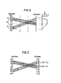
- Fig. 6 is a diagram which illustrates the application of a variable width equal weighted filter used for Filter I.
- Fig. 7 is a diagram which illustrates the application of medium and heavy equal weighted filters used for Filter II.
- Fig. 8 is a schematic block diagram illustrating the present method in machine implemented form.
- Fig. 1 illustrates the mechanism of the artifact. Point V represents a
detector 20, one of a plurality of detectors (two represented) 9 (see Fig. 8) disposed equiangularly aboutdetector circle 100. The position ofdetector 20 is defined by its angular displacement Δθ from the normal, represented bycenterline 12 emanating from point U which representsdetector 30. - Points P1 and P2 located on the perimeter of
circle 104 represent origins of the source of artifacts viewed bydetector 20. These two points are disposed alongcenter line 12 which intersectsisocenter 0 ofcircle 104. From the perspective ofdetector 20, point P1 is on the far side ofisocenter 0 while point P2 is on the near side thereof. - In the reconstruction process all points in this view will be projected to data line AB. The data line AB is normal to central ray CR which intersects point V and
isocenter 0. - Fig. 2 shows the projection of information from points P1, 0, and P2 onto the data line AB. Source width, source motion, and detector aperture combine to produce an effective point spread function (PSF) for each of the three data points P1, 0, and P2. The three PSFs are shown centered on P1', 0, and P2', respectively. The full width at half maximum (FWHM), i.e. the width of the projection function at half its amplitude, is indicated on Fig. 2. Since the points are separated by a distance greater than the FWHM, they cannot blend into a uniform distribution.
- Considering now only point P1, the view from
detector 30 produces a backprojected ray alongline 12 through theisocenter 0. The adjacent view of point P1 fromdetector 20 produces a backprojected ray alongline 14. In the center of a matrix of backprojections, these rays will be separated by a distance SF indicated on Fig. 2. Similarly, the above analysis for point P2 indicates that its corresponding rays will be separated by a distance S, as indicated on Fig. 2. - Fig. 3 shows the effect of backprojecting beams of finite width W about a
point 120 representing the origin of an artifact. The angle between rays sharing acommon intersection point 120 i6. Ifpoint 120 corresponds to point P1, then

- However, if
point 120 corresponds to point P2, then

- Outside a
circle 105 of radius Rc there will be no beam overlap. Not shown in Fig. 3 are the negative wings on each beam produced by convolution with a standard deblurring filter function. Inside thecircle 105 the summation of the negative wing values cancels out the positive beam portions so the net effect is a zero field everywhere except at the point being reconstructed. - Since the views of an exterior point are incomplete in the partial area scan, the above is not absolutely true, but for practical purposes, the cancellation is quite good. However, outside the
circle 105 cancellation is not complete. The spaces between the positive rays will contain negative values only and streaking artifact results from bones situated from the center of the region of interest a distance greater than critical radius Re. - The critical radius for
circle 105 of radius Re is given by the following expression:
- Inspection of this relationship shows the radius can be effectively increased by either reducing the angle Δθ between detectors or by increasing the beam width W. The former requires an increased number of detectors. That is a costly proposition and one that entails increased maintenance. Alternatively, increasing the beam width W can be effectively and simply achieved, however, by low pass filtering of the data in those views producing the artifact. The effect of the low pass filter is to effectively increase the beam width, W, and thereby effectively increase the critical radius to include the area of interest. Once that is accomplished, the artifact is eliminated by the cancellation achieved during reconstruction.
- The separation of the beams on the data line near the
isocenter 0 is given by the following expressions: - Far side points:

- D=Radius of
Detector Circle 100 and - R=Radius of
Circle 104 - Near side points:

- From these expressions the variable width of the low pass filter can be determined.
- Fig. 4 illustrates a
small scan circle 10 shown withinbody section 16 disposed withindetector circle 100. The area of diagnostic significance is fully contained within the region defined bysmall scan circle 10. For illustrative purposes only, thesmall scan circle 10, includes therewithin a section of the patient'sspinal cord 18 andspinal column 22. Located well outside thescan circle 10 arebone sections 24, the sources of the artifact. - From the perspective of
detector circle 100 which surroundsbody section 16 and hencebone sections 24, the locations aboutdetector circle 100 to which portions ofbone sections 24 would project are determined. For reference purposes, the horizontal is denoted 0° and angular displacements therefrom in counterclockwise rotation are indicated as negative. This convention is consistently followed in the diagrammatical illustrations of Figs. 5-7. - Fig. 5 illustrates where the shoulder attenuation values appear in the projection data based upon the example of Fig. 4. The shoulder located nearest the detectors first appears (as indicated on the left column) over the detector view angle range 23 to 10 degrees and disappears (as indicated on the right column) over the
range 1 to -13 degrees. The distant shoulder first appears on the right side of the projection data between 21 and 10 degrees and disappears between -22 and -34 degrees. A similar situation occurs 180 degrees around the scan circle with the nearest shoulder appearing between -167 and -181 degrees and disappearing between -190 and -203 degrees. The distant shoulder again appears on the right side between -146 and -158 degrees and disappears between -190 and -201 degrees. - For projection data of the
near shoulder 24, an equal weighted filter of width 2.75 mm (based on calculations for SN and equivalent to an 11 point filter for sample rate of four samples per millimeter at the centre of the scan circle) is sufficient to widen the discontinuities, i.e. effectively increase the critical radius such that they do not contribute to a streaking effect in the reconstructed image. Likewise, for thedistant shoulder 24, a filter of width 1.75 mm (based on calculations for SF and equivalent to a 7 point filter for data sampled at four samples per millimeter) is sufficient to cancel its effects. It is therefore only necessary to decide where in the projection data this filtering should take place. Fig. 4 shows the geometry that must be considered to determine at what view angles the shoulder projections appear. Once these angles have been determined, the regions in which the shoulder projections appear in the projection data can be outlined as shown in Fig. 5. - Two alternatives exist for processing the data: (1) Filter these regions with a filter which is variable in width as a function of view angle but constant along each projection. This filter is designated as Filter I. (2) Filter the regions with a filter which processes only those areas within the projections which contain the shoulder projections, one width for nearby shoulders, the other width for distant shoulders. This filter is designated as Filter II.
- Figs. 6 and 7 show where these filters are applied to the projection data.
- Integer N takes on values between 0 and 5 as determined by the function illustrated to the right of Fig. 6 which according to the following relationship assures an odd number of filter elements (since an even number of elements could cause a half element shift during filtration):
- Number of Filter Elements=NFE=2N+1 (4)
- (=11 for nearby shoulder projections
- =7 for far shoulder projections);
- Every projection line is filtered according to the N value given at the corresponding view angle. The region of heavy filtering H (hatched area) corresponds to projection lines filtered with N=5 (or NFE=11 as was determined to eliminate nearby shoulder artifacts);
- The regions on either side of heavy filtering are transient regions denoted T and represented by the ramps (since filtrations between NFE=0 and NFE=11 is required for these regions). The symmetrical situation occurs for view angles 180 degrees from those shown in the diagram, i.e. for the projections shown in the lower portion of Fig. 5.
- Fig. 7 indicates the application of alternative embodiment Filter II.
- The heavy filter (NFE=11, as determined above from SN) is applied to that portion of the projection data corresponding to projections of the nearby shoulder. The medium filter (NFE=7) is applied to that portion corresponding to the projections of the distant shoulder. Again the symmetrical situation occurs for the projections shown in the lower portion of Fig. 5.
- The advantage of Filter I is its simplicity and speed of operation. In the case in which an array processor is used for calculating the filtered output for the appropriate projections, only one call to the processor is necessary for each filter width being used, which may extend over several projection lines. For each projection line being processed by Filter II, two calls to the processor are required to filter the data. Therefore, the larger overhead for Filter II makes it a slower process. Furthermore, any misalignment of predicted shoulder projections in the case of Filter II will tend to cause streaking to appear sooner than in the case of
Filter 1. On the other hand, the minimal region operated on by Filter Il, leads to an improved spatial resolution in the two- dimensional reconstruction. As shown in Fig. 6, Filter I can be designed to insure full elimination of streaking in the central portion of the image by appropriately positioning the region in which the heaviest filtering (N=5) is being performed. Any streaking that may occur would only occur in the periphery of the image. This allows a minimal loss of resolution while eliminating the artifact in the most important area of the image. Because of this and its speed and simplicity, Filter I is preferred to eliminate the shoulder artifact. - Finally, Fig. 8 is a system diagram of the above. A radiation, in particular,
X-ray source 1 is shown with X-ray shielding 2 provided thereabout. Acollimator 3 is disposed about thesource 1 with which the angle of the radiation beam emanating from the source is modified. In particular, without collimation, the radiation source beam projects at a wide angle resulting in anormal scan circle 4 within which a section of abody 16 is fully enclosed. However, for purposes of a partial area scan, the beam is collimated to an angle x which accommodatessmall scan circle 10. Theshoulder portions 24 of thepatient having body 16 is shown. The patient lies on a support table 7 during the diagnostic procedure. - Circumscribing the
patient 16 is a plurality of detectors generally referred to as 9. These detectors are placed in equiangular relation aboutdetector circle 100. Ordinarily, data accumulated by each of thedetectors 9 are collected inData Memory 40. A subset of thedetectors 9 is a plurality ofdetectors 8 which "see" at least a portion of at least one of theshoulders 24 with theX-ray source 1 collimated forsmall scan circle 10 projection. Asignal harness 110 is provided for transmitting the data accumulated bydetectors 8 to Programmable LowPass Signal Filters 50. The remainingdetectors 9 are provided withconventional signal harness 111 for transmitting data accumulated by the remainingdetectors 9 to theData Memory 40. The signals processed in the Programmable LowPass Signal Filters 50 is also transmitted toData Memory 40 for subsequent projection completion byProjection Completion Circuits 60. Finally the completed projection is reconstructed by Convolver andBackprojector 70 and the reconstructed image is displayed byDisplay 80.
Claims (4)
Applications Claiming Priority (2)
| Application Number | Priority Date | Filing Date | Title |
|---|---|---|---|
| US06/098,431 US4333145A (en) | 1979-11-29 | 1979-11-29 | Method of high resolution partial area scan involving concentrated high density material outside the partial area |
| US98431 | 1987-12-18 |
Publications (3)
| Publication Number | Publication Date |
|---|---|
| EP0030144A2 EP0030144A2 (en) | 1981-06-10 |
| EP0030144A3 EP0030144A3 (en) | 1981-12-02 |
| EP0030144B1 true EP0030144B1 (en) | 1986-09-24 |
Family
ID=22269253
Family Applications (1)
| Application Number | Title | Priority Date | Filing Date |
|---|---|---|---|
| EP80304291A Expired EP0030144B1 (en) | 1979-11-29 | 1980-11-28 | Apparatus for minimising the effect of concentrated high density material outside a small scan circle in computed tomography |
Country Status (4)
| Country | Link |
|---|---|
| US (1) | US4333145A (en) |
| EP (1) | EP0030144B1 (en) |
| JP (1) | JPS5689242A (en) |
| DE (1) | DE3071781D1 (en) |
Families Citing this family (25)
| Publication number | Priority date | Publication date | Assignee | Title |
|---|---|---|---|---|
| US4442489A (en) * | 1979-06-16 | 1984-04-10 | U.S. Philips Corporation | Device for computed tomography |
| DE2924423A1 (en) * | 1979-06-16 | 1980-12-18 | Philips Patentverwaltung | METHOD FOR DETERMINING THE SPATIAL DISTRIBUTION OF THE ABSORPTION OF RADIATION IN A PLANE AREA |
| IL69327A (en) * | 1983-07-26 | 1986-11-30 | Elscint Ltd | Automatic misregistration correction |
| JPS60261436A (en) * | 1984-06-11 | 1985-12-24 | 株式会社 日立メデイコ | Ct apparatus |
| US4729100A (en) * | 1984-08-28 | 1988-03-01 | Kabushiki Kaisha Toshiba | CT System which convolutes projection data with a frequency varying filter function |
| US4674045A (en) * | 1984-12-31 | 1987-06-16 | Picker International Inc. | Filter for data processing |
| GB2181330B (en) * | 1985-09-26 | 1990-05-09 | Toshiba Kk | X-ray inspection apparatus |
| CA1274922A (en) * | 1987-09-11 | 1990-10-02 | Terence Taylor | Region of interest tomography employing a differential scanning technique |
| US5042077A (en) * | 1987-10-02 | 1991-08-20 | General Electric Company | Method of highlighting subtle contrast in graphical images |
| US5276614A (en) * | 1989-11-17 | 1994-01-04 | Picker International, Inc. | Dynamic bandwidth reconstruction |
| JPH02121636A (en) * | 1988-10-31 | 1990-05-09 | Yokogawa Medical Syst Ltd | Image processing method and apparatus for reducing streak |
| JPH02134148A (en) * | 1988-11-16 | 1990-05-23 | Toshiba Corp | Heart function analysis method |
| DE4135282C2 (en) * | 1991-10-25 | 1994-09-22 | Heimann Systems Gmbh & Co | X-ray scanner |
| US6246742B1 (en) * | 1999-06-22 | 2001-06-12 | General Electric Company | Local CT image reconstruction with limited x-ray exposure |
| US6580939B1 (en) * | 1999-11-04 | 2003-06-17 | Board Of Regents, The University Of Texas System | Method and system for reducing background artifacts from uniformly redundant array collimators in single photon emission computed tomography |
| DE10026566A1 (en) * | 2000-05-30 | 2001-12-13 | Siemens Ag | Computer tomograph |
| WO2002073174A2 (en) * | 2001-03-12 | 2002-09-19 | Koninklijke Philips Electronics N.V. | Fast computed tomography method |
| DE10201321B4 (en) * | 2002-01-15 | 2011-02-24 | Siemens Ag | Computed tomography device and method with active adaptation of the measuring electronics |
| US20070121778A1 (en) * | 2005-10-17 | 2007-05-31 | Siemens Corporate Research Inc | Method and System For Spinal Cord Detection In Computed Tomography Volume Data |
| US20070237287A1 (en) * | 2006-03-28 | 2007-10-11 | Predrag Sukovic | Ct scanner with automatic determination of volume of interest |
| US20070248206A1 (en) * | 2006-04-19 | 2007-10-25 | Predrag Sukovic | Ct scanner with untracked markers |
| US7548604B2 (en) * | 2007-01-04 | 2009-06-16 | General Electric Company | Method and apparatus for reduction of metal artifacts in CT imaging |
| US9569891B2 (en) * | 2010-07-16 | 2017-02-14 | Tyoterveyslaitos | Method, an apparatus and an arrangement for visualizing information |
| JP7553307B2 (en) * | 2019-10-02 | 2024-09-18 | キヤノンメディカルシステムズ株式会社 | X-ray diagnostic equipment |
| US12169885B2 (en) * | 2022-02-25 | 2024-12-17 | GE Precision Healthcare LLC | Computer processing techniques for streak reduction in computed tomography images |
Family Cites Families (8)
| Publication number | Priority date | Publication date | Assignee | Title |
|---|---|---|---|---|
| US3696249A (en) * | 1970-09-14 | 1972-10-03 | Itek Corp | Detail boundary detection systems |
| CA939078A (en) * | 1971-11-24 | 1973-12-25 | Atomic Energy Of Canada Limited - Energie Atomique Du Canada, Limitee | Method for non-destructive densitometric measurement of small volumes inside irregularly shaped non-uniform objects |
| SE373279B (en) * | 1973-05-11 | 1975-02-03 | Atomenergi Ab | PROCEDURE AND DEVICE FOR EXAMINING A PART OF A BIOLOGICAL TISSUE |
| US4069422A (en) * | 1973-06-01 | 1978-01-17 | E M I Limited | Apparatus for examining objects by means of penetrating radiation |
| US4149248A (en) * | 1975-12-23 | 1979-04-10 | Varian Associates, Inc. | Apparatus and method for reconstructing data |
| GB1578442A (en) * | 1976-07-01 | 1980-11-05 | Emi Ltd | Radiography |
| JPS5394787A (en) * | 1977-01-31 | 1978-08-19 | Toshiba Corp | Tomographic diagnostic equipment by radiation |
| US4217641A (en) * | 1978-04-28 | 1980-08-12 | U.S. Philips Corporation | Correction for polychromatic X-ray distortion in CT images |
-
1979
- 1979-11-29 US US06/098,431 patent/US4333145A/en not_active Expired - Lifetime
-
1980
- 1980-11-28 DE DE8080304291T patent/DE3071781D1/en not_active Expired
- 1980-11-28 EP EP80304291A patent/EP0030144B1/en not_active Expired
- 1980-11-28 JP JP16681380A patent/JPS5689242A/en active Pending
Also Published As
| Publication number | Publication date |
|---|---|
| DE3071781D1 (en) | 1986-10-30 |
| EP0030144A2 (en) | 1981-06-10 |
| EP0030144A3 (en) | 1981-12-02 |
| JPS5689242A (en) | 1981-07-20 |
| US4333145A (en) | 1982-06-01 |
Similar Documents
| Publication | Publication Date | Title |
|---|---|---|
| US4333145A (en) | Method of high resolution partial area scan involving concentrated high density material outside the partial area | |
| US6078638A (en) | Pixel grouping for filtering cone beam detector data during 3D image reconstruction | |
| US5864598A (en) | Methods and apparatus for scanning an object in a computed tomography system | |
| US5416815A (en) | Adaptive filter for reducing streaking artifacts in x-ray tomographic images | |
| EP0492895B1 (en) | Reconstructing 3-D images | |
| EP0746821B1 (en) | Method for rebinning and for correcting cone beam error in a fan beam computed tomographic scanner system | |
| US5881123A (en) | Simplified cone beam image reconstruction using 3D backprojection | |
| US7023951B2 (en) | Method and apparatus for reduction of artifacts in computed tomography images | |
| US6574297B2 (en) | System and method for image reconstruction in a cone beam imaging system | |
| US6490333B1 (en) | Methods and apparatus for cone-tilted parallel sampling and reconstruction | |
| US6018561A (en) | Mask boundary correction in a cone beam imaging system using simplified filtered backprojection image reconstruction | |
| US6704440B1 (en) | Method and apparatus for processing a medical image containing clinical and non-clinical regions | |
| EP1306807A2 (en) | A tomographic image reconstruction method for tomosynthesis | |
| EP0370829B1 (en) | Diagnostic imaging apparatus | |
| US6751284B1 (en) | Method and system for tomosynthesis image enhancement using transverse filtering | |
| US4570224A (en) | Combining rebinned and unrebinned parallel ray data with unequal lateral spacing to create tomograph images | |
| JPH0412969B2 (en) | ||
| US5383119A (en) | Method and apparatus for acquiring complete radon data for exactly reconstructing a three dimensional computerized tomography image of a portion of an object irradiated by a cone beam source | |
| US20070019851A1 (en) | Image processing apparatus and X-ray CT apparatus | |
| JPH07143979A (en) | Method and apparatus for reducing artifacts in tomographic images | |
| US5043890A (en) | Compensation of computed tomography data for objects positioned outside the field of view of the reconstructed image | |
| EP0196538B1 (en) | Astigmatic collimator | |
| US5561695A (en) | Methods and apparatus for reducing image artifacts | |
| WO2008109254A1 (en) | Geometry-dependent filtering in ct method and apparatus | |
| EP0989521B1 (en) | Fluoroscopy image reconstruction |
Legal Events
| Date | Code | Title | Description |
|---|---|---|---|
| PUAI | Public reference made under article 153(3) epc to a published international application that has entered the european phase |
Free format text: ORIGINAL CODE: 0009012 |
|
| AK | Designated contracting states |
Designated state(s): BE DE FR GB NL SE |
|
| PUAL | Search report despatched |
Free format text: ORIGINAL CODE: 0009013 |
|
| AK | Designated contracting states |
Designated state(s): BE DE FR GB NL SE |
|
| 17P | Request for examination filed |
Effective date: 19820507 |
|
| GRAA | (expected) grant |
Free format text: ORIGINAL CODE: 0009210 |
|
| AK | Designated contracting states |
Kind code of ref document: B1 Designated state(s): BE DE FR GB NL SE |
|
| PG25 | Lapsed in a contracting state [announced via postgrant information from national office to epo] |
Ref country code: NL Effective date: 19860924 Ref country code: FR Free format text: THE PATENT HAS BEEN ANNULLED BY A DECISION OF A NATIONAL AUTHORITY Effective date: 19860924 Ref country code: BE Effective date: 19860924 |
|
| PG25 | Lapsed in a contracting state [announced via postgrant information from national office to epo] |
Ref country code: SE Effective date: 19860930 |
|
| REF | Corresponds to: |
Ref document number: 3071781 Country of ref document: DE Date of ref document: 19861030 |
|
| EN | Fr: translation not filed | ||
| NLV1 | Nl: lapsed or annulled due to failure to fulfill the requirements of art. 29p and 29m of the patents act | ||
| GBPC | Gb: european patent ceased through non-payment of renewal fee | ||
| PLBE | No opposition filed within time limit |
Free format text: ORIGINAL CODE: 0009261 |
|
| STAA | Information on the status of an ep patent application or granted ep patent |
Free format text: STATUS: NO OPPOSITION FILED WITHIN TIME LIMIT |
|
| 26N | No opposition filed | ||
| PG25 | Lapsed in a contracting state [announced via postgrant information from national office to epo] |
Ref country code: GB Effective date: 19881118 |
|
| PGFP | Annual fee paid to national office [announced via postgrant information from national office to epo] |
Ref country code: DE Payment date: 19921212 Year of fee payment: 13 |
|
| PG25 | Lapsed in a contracting state [announced via postgrant information from national office to epo] |
Ref country code: DE Effective date: 19940802 |