EP0029080B1 - Gate valve with position responsive interlock - Google Patents
Gate valve with position responsive interlock Download PDFInfo
- Publication number
- EP0029080B1 EP0029080B1 EP79890050A EP79890050A EP0029080B1 EP 0029080 B1 EP0029080 B1 EP 0029080B1 EP 79890050 A EP79890050 A EP 79890050A EP 79890050 A EP79890050 A EP 79890050A EP 0029080 B1 EP0029080 B1 EP 0029080B1
- Authority
- EP
- European Patent Office
- Prior art keywords
- gate
- guide rail
- assembly
- rocker arm
- members
- Prior art date
- Legal status (The legal status is an assumption and is not a legal conclusion. Google has not performed a legal analysis and makes no representation as to the accuracy of the status listed.)
- Expired
Links
Images

Classifications
-
- F—MECHANICAL ENGINEERING; LIGHTING; HEATING; WEAPONS; BLASTING
- F16—ENGINEERING ELEMENTS AND UNITS; GENERAL MEASURES FOR PRODUCING AND MAINTAINING EFFECTIVE FUNCTIONING OF MACHINES OR INSTALLATIONS; THERMAL INSULATION IN GENERAL
- F16K—VALVES; TAPS; COCKS; ACTUATING-FLOATS; DEVICES FOR VENTING OR AERATING
- F16K3/00—Gate valves or sliding valves, i.e. cut-off apparatus with closing members having a sliding movement along the seat for opening and closing
- F16K3/02—Gate valves or sliding valves, i.e. cut-off apparatus with closing members having a sliding movement along the seat for opening and closing with flat sealing faces; Packings therefor
- F16K3/16—Gate valves or sliding valves, i.e. cut-off apparatus with closing members having a sliding movement along the seat for opening and closing with flat sealing faces; Packings therefor with special arrangements for separating the sealing faces or for pressing them together
- F16K3/18—Gate valves or sliding valves, i.e. cut-off apparatus with closing members having a sliding movement along the seat for opening and closing with flat sealing faces; Packings therefor with special arrangements for separating the sealing faces or for pressing them together by movement of the closure members
- F16K3/184—Gate valves or sliding valves, i.e. cut-off apparatus with closing members having a sliding movement along the seat for opening and closing with flat sealing faces; Packings therefor with special arrangements for separating the sealing faces or for pressing them together by movement of the closure members by means of cams
- F16K3/186—Gate valves or sliding valves, i.e. cut-off apparatus with closing members having a sliding movement along the seat for opening and closing with flat sealing faces; Packings therefor with special arrangements for separating the sealing faces or for pressing them together by movement of the closure members by means of cams by means of cams of wedge from
Definitions
- the invention relates to a gate valve comprising a housing having a valve chamber therein and inlet and outlet flow passageways communicating with the valve chamber, a seat about each flow passageway, an expansible ported gate assembly mounted in said chamber for linear movement between open and closed positions relative to the passageways wherein said gate assembly comprises a gate member and a segment member, the gate member being connected to a control stem extending to one end of the housing while the segment member floats in dependence on the gate member, said two members having parallel outer sealing surfaces to engage the valve seats and complementary inner surfaces so that the two members interface one another, each of said inner surfaces being a bifurcated surface inclined with respect to the sealing surfaces and diverging away from a point at about its mid-length to form two pairs of wedging surface which operate to expand the assembly perpendicularly to said seats into sealing engagement therewith, said members having a pair of opposed side surfaces joining said outer and inner surfaces, and also having the aligned ports through one of the pairs of wedging surfaces, said gate assembly also having a positioning device inter-connecting said gate
- Gate valves of the sliding gate and segment type have been used extensively for many years, and from the beginning, the design engineer has faced this problem. At either end of the stroke of the pair of members, they must be expanded in thickness by stopping one member and pushing or pulling on the other to cause it to climb the wedging surface of the halted member, thus sealing against the valve seats. Between extremities, on the other hand, it is necessary to minimize the thickness of the sliding members so that they will not bind against the valve seats and jamb the gate and segment in a half-and-half position.
- the centralizer type of structure is exemplified in US-A-2 583 512. Even a summary description of this structure would be too lengthy to set forth here, but it will be noted that the structure is complicated and includes a pair of fixed guides and a mechanical interlock between gate and segment.
- the latter includes a guide shoe which, during any sliding movement of the gate and segment, is constrained to travel in contact with both fixed guides; in such position, the elements linked to the guide shoe force the gate and segment to stay in a central position in which they are pressed together with both pairs of inclined surfaces in tight contact.
- a gate valve is known in accordance with the prior art portion of claim 1 (US-A-2 855 175) in which the rocker arm pivotally secured to the segment member is centering said member with respect to the gate member by abutting with its curved end faces the opposed surfaces of a pair of spaced lugs protruding from the side surface of the gate member, as long as the gate assembly is somewhere between the open and closed positions.
- Cam surfaces adjacent the opposed extremities of the rocker arm cooperate with the guide rail at one side thereof, which has sloping en'd surfaces on both ends.
- At the other side of the rocker arm there is a guide rail which is cut away at its mid portion.
- one or the other end portion, resp., of the rocker arm may move into the cut away portion of the latter guide rail whereby the rocker arm is rotatable to permit relative displacement between' the gate member and the segment member so that said members may move to expanded positions.
- the invention as claimed is intended to remedy these drawbacks. It solves the problem by providing the guide rail with a single interruption therein, and the rocker arm having a slot engaging a pin protruding from the corresponding side surface of the other gate assembly member and having a pair of downwardly extending lobes at its opposed extremities, on opposed sides of its connection to the two members, said lobes contacting and riding on said guide rail except when one of them enters the interruption in the guide rail and permits the rocker arm to rotate, whereby during movement of the gate assembly between the two sealing positions at the ends of its stroke, said rocker arm lobes are both in contact with the guide rail and maintain the two members in non-wedging and non-expansive relationship with one another, preventing drag between the moving assembly and the valve seats, while at the ends of the stroke of the assembly, one of said lobes enters the interruption in the guide rail and permits the two members to be wedged into sealing relationship with the valve seats.
- the advantages offered by the invention are mainly that only the guide rail or guide rails adjacent one of the sealing surfaces of the gate assembly must be provided with a control track which has the shape of a single interruption between two rail segments, and that the use of control transmission gearing subjected to any considerable friction is avoided.
- the rocker arm may be a simple plate member having the general shape of an isosceles triangle having an elongated base extending generally parallel to said guide rail and said lobes extending downwardly from said base toward the guide rail.
- the distance between the rocker arm lobes shall be equal to the distance traveled by the gate valve assembly between its end positions, whereby said interruption in the guide rail accommodates said lobes alternately as the assembly reaches its opposed end positions and the rocker arm is urged into clockwise and counterclockwise rotated positions.
- the interruption in the guide rail is located along its length to correspond to the end positions of the slidable gate assembly; i.e., the lobe at one end of the rocker arm can enter the interruption only when the segment member can move no further and additional force is exerted on the gate.
- This causes the rocker arm to pivot and permits the gate to slide on the wedge surface of the segment, expanding the thickness of the gate assembly and causing it to seal against the opposed seats.
- both lobes of the rocker arm contact the guide rail and keep both pairs of wedge surfaces in tight contact, minimizing their overall thickness and preventing any drag against the valve seats.
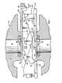
- Figures 1 and 2 show a gate valve 10 comprising a housing 12 having a through passageway 14, 16 interrupted by an orthogonal interior valve chamber 18 which houses the gate mechanism of the valve.
- the two portions 14, 16 of the interrupted fluid passageway intersect the gate operating chamber 18 in opposed ports, respectively 20 and 22, which lie in opposed parallel planes and are there provided with seats. While various types of seats including metal-to-metal may be utilized, the drawing illustrates replaceable seats 24 secured in the indicated counterbores in the housing wall which defines ports 20 and 22.
- the assembly includes a pair of seat skirts 26 which surround the seats and are provided with a pair of inturned edge flanges 28 which serve as guides for the traveling gate assembly.
- one of the seat skirts is modified and is designated 26', the modification consisting of providing in the flanges or guard rails 28' a gap 30 which is disposed along the length of rail 28' at a preselected location enabling it to receive one of the lobes 64 of rocker arm 54, as discussed further below.
- the openings 32 in skirts 26 26' are of a diameter to receive the seats 24, which protrude from ports 20 and 22 through openings 32 so that the sealing contacts are between the flat surfaces 48 and 50 of the gate members and the planar outer ends 62 of the seats.
- These openings 32 are aligned with passageways 82 and 80 in gate 36 and segment 38 when the latter are in their end position corresponding to an open valve.
- the two guard rails 28 and 28' of either skirt 26 or 26' extend lengthwise in the direction of travel of the gate assembly, of course, and are spaced from one another by the width of such assembly, plus a small operational clearance.
- Figure 1 shows the gate assembly 34, consisting of gate 36 and segment 38 in its traveling attitude, which is the attitude it is designed and forced to assume in all positions of gate assembly 34 except at the opposed ends of its linear stroke.
- Such two positions which can be designated sealed open and sealed closed, are the only two positions calling for wedging action between the gate 36 and segment 38.
- the divergent wedge surfaces 40 and 42 of gate 36 are in tight contact with the corresponding interfacing wedge surfaces 44 and 46 of segment 36, 40 with 44 and 42 with 46. It should be noted that there is no gap between either of these two pairs of contacting surfaces.
- the overall thickness of the assembly 34 measured along a perpendicular between the opposed and parallel flat outer surfaces 48 and 50 of segment 38 and gate 36, is at a minimum. With such minimum thickness, there is an operational clearance between each sealing surface 48 and 50 and the sealing surfaces 62 of valve seats 24, insuring that the gate assembly 34 can be moved without binding.
- the rocker arm 54 is basically a thin plate having the general form of an isosceles triangle with its base leg extending generally parallel to the guide rail 28'..At the opposed ends of this base leg, a pair of lobes 64 extend downwardly toward the guide rail, and in the traveling attitude of the assembly shown in Figure 1, these lobes 64 both contact the upper edge of the guide rail.
- the pin 56 extends through rocker arm 54 and is secured in an opening in the gate member 36. It serves as the pivot point for the rocker arm, and moves linearly with the rocker arm with each stroke.
- Rocker arm 54 thus has only one degree of freedom, rotation about pivot pin 56, and so long as both of its lobes 64 are in contact with guide rail 28', even this one degree of freedom can not be exercised.
- the positioning device 52 is completed by the pin 58 secured in and extending from the side surface of segment 38 and through the slot 66 in rocker 54.
- Slot 66 has a width measured along the direction of the gate assembly to receive pin 58 in snug relationship but is elongated in the orthogonal direction, in the direction of fluid flow through the valve.
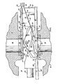
- Figure 2 actually shows the positions of the parts at the end of two steps in a sealing sequence.
- the segment member 38 of the assembly has contacted stop 72, which is part of the fixed housing 12, halting any further movement of this member to the right.
- stop 72 which is part of the fixed housing 12, halting any further movement of this member to the right.
- continued rightward thrust applied to gate member 36 through the stem 70 has caused it to move further to the right, further than segment 38.
- wedge surface 40 of the gate pushes against wedge surface 44 of the segment and actually slides along it for a short distance.
- the segment 38 is lifted up, pushing it into sealing contact with the upper seat 24, and at the same time the gate member 36 is pushed into sealing contact with lower seat 24.
- a gap 74 is opened between wedge surfaces 42 and 46, the size of which gap is indicative of the increase in thickness of the gate assembly.
- Such expansion of the gate assembly is accompanied by a counter-clockwise rotation of rocker 54, to that its left hand lobe 64 enters gap 30.
- Such rotation occurs because pivot pin 56 moves to the right relative to slot pin 58, the effect being the same as though pin 58 has moved to the left relative to pin 56.
- Pin 58 pushes to the left against the wall of slot 66, bringing about the rotation. It would seem that such pushing action would occur even if there were no slot 66, i.e., if this opening were circular, receiving pin 58 snugly on all sides.
- the opening must be slotted as shown to accommodate the movement of pin 58 upwardly as segment 38 is raised during the wedging action; without the slot, such upward movement can not take place and the gate and segment members would remain locked in their traveling relationship.
Landscapes
- Engineering & Computer Science (AREA)
- General Engineering & Computer Science (AREA)
- Mechanical Engineering (AREA)
- Sliding Valves (AREA)
- Valve-Gear Or Valve Arrangements (AREA)
Abstract
Description
- The invention relates to a gate valve comprising a housing having a valve chamber therein and inlet and outlet flow passageways communicating with the valve chamber, a seat about each flow passageway, an expansible ported gate assembly mounted in said chamber for linear movement between open and closed positions relative to the passageways wherein said gate assembly comprises a gate member and a segment member, the gate member being connected to a control stem extending to one end of the housing while the segment member floats in dependence on the gate member, said two members having parallel outer sealing surfaces to engage the valve seats and complementary inner surfaces so that the two members interface one another, each of said inner surfaces being a bifurcated surface inclined with respect to the sealing surfaces and diverging away from a point at about its mid-length to form two pairs of wedging surface which operate to expand the assembly perpendicularly to said seats into sealing engagement therewith, said members having a pair of opposed side surfaces joining said outer and inner surfaces, and also having the aligned ports through one of the pairs of wedging surfaces, said gate assembly also having a positioning device inter-connecting said gate and segment members, said positioning device including a guide rail secured to the interior of said valve chamber adjacent one of said seats and extending parallel to the direction of travel of the gate assembly, and a rocker arm pivotally secured to one of the two gate assembly members through one of the side surfaces thereof adjacent said guide rail, the rocker arm with its opposed extremities contacting said guide rail.
- Gate valves of the sliding gate and segment type have been used extensively for many years, and from the beginning, the design engineer has faced this problem. At either end of the stroke of the pair of members, they must be expanded in thickness by stopping one member and pushing or pulling on the other to cause it to climb the wedging surface of the halted member, thus sealing against the valve seats. Between extremities, on the other hand, it is necessary to minimize the thickness of the sliding members so that they will not bind against the valve seats and jamb the gate and segment in a half-and-half position.
- Prior art solutions to this problem fall into two general categories, springs and centrali- zers. The former is exemplified in US-A-2 954 960. This patent discloses the use of an ox yoke spring over a central pin in one member and having its ends tucked under a pair of opposed pins protruding from the other member. The spring forces the two members together so long as no opposed axial forces are exerted on the members. At the end of a stroke, when the floating segment member is halted by contact with a fixed stop member, an axial force exerted on the gate member through the control stem causes it to climb up the now fixed segment member, thus expanding the assembly and causing it to seal against the opposed valve seats. It should be noted that with this type of assembly, the force applied to the gate member must first overcome the spring force.
- The centralizer type of structure is exemplified in US-A-2 583 512. Even a summary description of this structure would be too lengthy to set forth here, but it will be noted that the structure is complicated and includes a pair of fixed guides and a mechanical interlock between gate and segment. The latter includes a guide shoe which, during any sliding movement of the gate and segment, is constrained to travel in contact with both fixed guides; in such position, the elements linked to the guide shoe force the gate and segment to stay in a central position in which they are pressed together with both pairs of inclined surfaces in tight contact.
- A gate valve is known in accordance with the prior art portion of claim 1 (US-A-2 855 175) in which the rocker arm pivotally secured to the segment member is centering said member with respect to the gate member by abutting with its curved end faces the opposed surfaces of a pair of spaced lugs protruding from the side surface of the gate member, as long as the gate assembly is somewhere between the open and closed positions. Cam surfaces adjacent the opposed extremities of the rocker arm cooperate with the guide rail at one side thereof, which has sloping en'd surfaces on both ends. At the other side of the rocker arm there is a guide rail which is cut away at its mid portion. In the open and closed positions of the gate assembly one or the other end portion, resp., of the rocker arm may move into the cut away portion of the latter guide rail whereby the rocker arm is rotatable to permit relative displacement between' the gate member and the segment member so that said members may move to expanded positions.
- In connection with said rotation of the rocker arm considerable frictional reacting forces are to be expected occurring between the lug on the side surface of the gate member and the curved end face of the rocker arm. Moreover, the opposing rails are to be specially shaped and are to be carefully aligned within the housing of the gate valve and with respect to each other for obtaining the desired cooperation.
- The invention as claimed is intended to remedy these drawbacks. It solves the problem by providing the guide rail with a single interruption therein, and the rocker arm having a slot engaging a pin protruding from the corresponding side surface of the other gate assembly member and having a pair of downwardly extending lobes at its opposed extremities, on opposed sides of its connection to the two members, said lobes contacting and riding on said guide rail except when one of them enters the interruption in the guide rail and permits the rocker arm to rotate, whereby during movement of the gate assembly between the two sealing positions at the ends of its stroke, said rocker arm lobes are both in contact with the guide rail and maintain the two members in non-wedging and non-expansive relationship with one another, preventing drag between the moving assembly and the valve seats, while at the ends of the stroke of the assembly, one of said lobes enters the interruption in the guide rail and permits the two members to be wedged into sealing relationship with the valve seats.
- The advantages offered by the invention are mainly that only the guide rail or guide rails adjacent one of the sealing surfaces of the gate assembly must be provided with a control track which has the shape of a single interruption between two rail segments, and that the use of control transmission gearing subjected to any considerable friction is avoided.
- The rocker arm may be a simple plate member having the general shape of an isosceles triangle having an elongated base extending generally parallel to said guide rail and said lobes extending downwardly from said base toward the guide rail.
- Preferably there are a pair of said guide rails secured to the opposed pair of seats and a pair of rocker arms pivotally secured to the opposed sides of the gate and segment members. Thereby a symmetrical exertion of forces onto said members is obtained.
- The distance between the rocker arm lobes shall be equal to the distance traveled by the gate valve assembly between its end positions, whereby said interruption in the guide rail accommodates said lobes alternately as the assembly reaches its opposed end positions and the rocker arm is urged into clockwise and counterclockwise rotated positions.
- The interruption in the guide rail is located along its length to correspond to the end positions of the slidable gate assembly; i.e., the lobe at one end of the rocker arm can enter the interruption only when the segment member can move no further and additional force is exerted on the gate. This causes the rocker arm to pivot and permits the gate to slide on the wedge surface of the segment, expanding the thickness of the gate assembly and causing it to seal against the opposed seats. Between such extremities, both lobes of the rocker arm contact the guide rail and keep both pairs of wedge surfaces in tight contact, minimizing their overall thickness and preventing any drag against the valve seats.
- One way of carrying out the invention is described in detail below with reference to the drawings which illustrate a specific embodiment, in which:-
- Figure 1 is a longitudinal section through the body of a gate valve embodying the invention, this view showing the positions of the parts during travel of the gate assembly between open and closed positions, or vice versa.
- Figure 2 is a longitudinal section like Figure 1, this view showing the positions of the parts in either open or closed positions, after the gate assembly has been expanded to seal against the opposed valve seats.
- Figure 3 is an exploded isometric view showing the principal components of the assembly.
- Figures 1 and 2 show a
gate valve 10 comprising a housing 12 having a throughpassageway interior valve chamber 18 which houses the gate mechanism of the valve. The twoportions gate operating chamber 18 in opposed ports, respectively 20 and 22, which lie in opposed parallel planes and are there provided with seats. While various types of seats including metal-to-metal may be utilized, the drawing illustratesreplaceable seats 24 secured in the indicated counterbores in the housing wall which definesports - The assembly includes a pair of
seat skirts 26 which surround the seats and are provided with a pair of inturnededge flanges 28 which serve as guides for the traveling gate assembly. In the present invention, one of the seat skirts is modified and is designated 26', the modification consisting of providing in the flanges or guard rails 28' agap 30 which is disposed along the length of rail 28' at a preselected location enabling it to receive one of thelobes 64 ofrocker arm 54, as discussed further below. - It should be noted that the
openings 32 inskirts 26 26' are of a diameter to receive theseats 24, which protrude fromports openings 32 so that the sealing contacts are between theflat surfaces outer ends 62 of the seats. Theseopenings 32, of course, are aligned withpassageways gate 36 andsegment 38 when the latter are in their end position corresponding to an open valve. The twoguard rails 28 and 28' of eitherskirt 26 or 26' extend lengthwise in the direction of travel of the gate assembly, of course, and are spaced from one another by the width of such assembly, plus a small operational clearance. - Figure 1 shows the
gate assembly 34, consisting ofgate 36 andsegment 38 in its traveling attitude, which is the attitude it is designed and forced to assume in all positions ofgate assembly 34 except at the opposed ends of its linear stroke. Such two positions, which can be designated sealed open and sealed closed, are the only two positions calling for wedging action between thegate 36 andsegment 38. In all other positions, thedivergent wedge surfaces gate 36 are in tight contact with the correspondinginterfacing wedge surfaces segment assembly 34, measured along a perpendicular between the opposed and parallel flatouter surfaces segment 38 andgate 36, is at a minimum. With such minimum thickness, there is an operational clearance between eachsealing surface sealing surfaces 62 ofvalve seats 24, insuring that thegate assembly 34 can be moved without binding. - Such gapless contact between the diverging wedge surfaces 40-44 and 42-46 is insured by the disposition of the
positioning device assembly 52, consisting of therocker arm 54 and the pair ofpins rocker arm 54 is basically a thin plate having the general form of an isosceles triangle with its base leg extending generally parallel to the guide rail 28'..At the opposed ends of this base leg, a pair oflobes 64 extend downwardly toward the guide rail, and in the traveling attitude of the assembly shown in Figure 1, theselobes 64 both contact the upper edge of the guide rail. - The
pin 56 extends throughrocker arm 54 and is secured in an opening in thegate member 36. It serves as the pivot point for the rocker arm, and moves linearly with the rocker arm with each stroke.Rocker arm 54 thus has only one degree of freedom, rotation aboutpivot pin 56, and so long as both of itslobes 64 are in contact with guide rail 28', even this one degree of freedom can not be exercised. - The
positioning device 52 is completed by thepin 58 secured in and extending from the side surface ofsegment 38 and through theslot 66 inrocker 54.Slot 66 has a width measured along the direction of the gate assembly to receivepin 58 in snug relationship but is elongated in the orthogonal direction, in the direction of fluid flow through the valve. - In Figure 1, the gate assembly is being pushed toward the right end position by the
stem 70, which is rigidly secured to thegate 36, carryingsegment 38 with the assembly. Although theleft hand lobe 64 is about to encounter thegap 30 in guide rail 28', the entire assembly is free to move to the right in the figure until one member of the gate assembly encounters a stop. It is important to note that the positioning device is not self operating; there is no rotation of therocker arm 54 simply because alobe 64 is in registry with the gap. Something further must occur before the rocker arm rotates; it must be compelled to rotate. - That further action is illustrated in Figure 2, which actually shows the positions of the parts at the end of two steps in a sealing sequence. First, the
segment member 38 of the assembly has contactedstop 72, which is part of the fixed housing 12, halting any further movement of this member to the right. Secondly, continued rightward thrust applied togate member 36 through thestem 70 has caused it to move further to the right, further thansegment 38. In so doing,wedge surface 40 of the gate pushes againstwedge surface 44 of the segment and actually slides along it for a short distance. Thesegment 38 is lifted up, pushing it into sealing contact with theupper seat 24, and at the same time thegate member 36 is pushed into sealing contact withlower seat 24. Agap 74 is opened betweenwedge surfaces - Such expansion of the gate assembly is accompanied by a counter-clockwise rotation of
rocker 54, to that itsleft hand lobe 64 entersgap 30. Such rotation occurs becausepivot pin 56 moves to the right relative to slotpin 58, the effect being the same as thoughpin 58 has moved to the left relative to pin 56.Pin 58 pushes to the left against the wall ofslot 66, bringing about the rotation. It would seem that such pushing action would occur even if there were noslot 66, i.e., if this opening were circular, receivingpin 58 snugly on all sides. However, the opening must be slotted as shown to accommodate the movement ofpin 58 upwardly assegment 38 is raised during the wedging action; without the slot, such upward movement can not take place and the gate and segment members would remain locked in their traveling relationship. - It is also important to note that, although it is necessary that the rocker arm rotate as described in order that the gate assembly expand its thickness and seal against the valve seats, the time when such expansion in thickness occurs is not dictated by the time when the
lobe 64 arrives in the proximity ofgap 30. The chain of events is initiated by the stopping ofsegment 38 bystop member 72, and then by the continued travel ofgate 36. Thus, the precise location ofgap 30 along guide rail 28' is not critical, and some manufacturing tolerance is permissible. - Having read the description of one sealing sequence, the sequence of the reverse movement will be apparent to the reader. As the rightward thrust through
stem 70 is relaxed and a leftward pull is exerted through it ongate 36, the gate will move leftward a short distance to closegap 74. Such short motion will at the same timecause rocker arm 54 to rotate clockwise to its Figure 1 position, aided if necessary by the cam surface 76 at the left end ofgap 30. This rotation will pullsegment 38 andgate 36 back into their minimum thickness positions with both pairs of interfacing wedge surfaces in tight contact. - The reverse stroke, leftward in the figures, will be as depicted in Figure 1, and the sequence at the end of such stroke will be more or less a mirror image of that described. The wedging and expansion and sealing will be initiated when the left hand end of
segment 38 strikes a fixed stop and further pull is applied to the gate member. A gap will be formed between wedge surfaces 40 and 44 aswedge surface 42 pushes against 46 andforces segment 38 into sealing position. This time therocker arm 54 rotates clockwise, and theright hand lobe 64 enters thesame gap 30. Again, the precise location of the gap is not critical. - Having described a preferred embodiment, the present inventor wishes it to be known that he does not consider himself limited thereby. Many substantially similar means for accomplishing the same result in substantially the same manner will be apparent to those of average skill in the art, and such means are to be considered within the scope of the invention, which is to be judged only by the appended claims.
Claims (4)
Priority Applications (2)
| Application Number | Priority Date | Filing Date | Title |
|---|---|---|---|
| EP79890050A EP0029080B1 (en) | 1979-11-16 | 1979-11-16 | Gate valve with position responsive interlock |
| AT79890050T ATE6298T1 (en) | 1979-11-16 | 1979-11-16 | SLIDE WITH POSITION DEPENDENT LOCKING. |
Applications Claiming Priority (1)
| Application Number | Priority Date | Filing Date | Title |
|---|---|---|---|
| EP79890050A EP0029080B1 (en) | 1979-11-16 | 1979-11-16 | Gate valve with position responsive interlock |
Publications (2)
| Publication Number | Publication Date |
|---|---|
| EP0029080A1 EP0029080A1 (en) | 1981-05-27 |
| EP0029080B1 true EP0029080B1 (en) | 1984-02-15 |
Family
ID=8186558
Family Applications (1)
| Application Number | Title | Priority Date | Filing Date |
|---|---|---|---|
| EP79890050A Expired EP0029080B1 (en) | 1979-11-16 | 1979-11-16 | Gate valve with position responsive interlock |
Country Status (2)
| Country | Link |
|---|---|
| EP (1) | EP0029080B1 (en) |
| AT (1) | ATE6298T1 (en) |
Citations (1)
| Publication number | Priority date | Publication date | Assignee | Title |
|---|---|---|---|---|
| US2954960A (en) * | 1956-12-24 | 1960-10-04 | Acf Ind Inc | Non-floating seat structure for expanding gate valves |
Family Cites Families (4)
| Publication number | Priority date | Publication date | Assignee | Title |
|---|---|---|---|---|
| DE709220C (en) * | 1936-11-20 | 1941-08-09 | Buschbeck & Hebenstreit | Two-plate gate valve, whose shut-off plates, which can be pressed onto the opposite seats, are controlled by angle levers which are hinged at one end to the slide frame which can be moved up and down |
| US2583512A (en) * | 1950-01-16 | 1952-01-22 | W K M Company | Gate valve |
| US2855175A (en) * | 1953-06-19 | 1958-10-07 | Calvin D Dunbar | Gate valve |
| US3051434A (en) * | 1959-01-09 | 1962-08-28 | Acf Ind Inc | Back seating for valve stems |
-
1979
- 1979-11-16 AT AT79890050T patent/ATE6298T1/en not_active IP Right Cessation
- 1979-11-16 EP EP79890050A patent/EP0029080B1/en not_active Expired
Patent Citations (1)
| Publication number | Priority date | Publication date | Assignee | Title |
|---|---|---|---|---|
| US2954960A (en) * | 1956-12-24 | 1960-10-04 | Acf Ind Inc | Non-floating seat structure for expanding gate valves |
Also Published As
| Publication number | Publication date |
|---|---|
| ATE6298T1 (en) | 1984-03-15 |
| EP0029080A1 (en) | 1981-05-27 |
Similar Documents
| Publication | Publication Date | Title |
|---|---|---|
| US4188014A (en) | Gate valve with position responsive interlock | |
| US5660153A (en) | Valve control system | |
| US2583512A (en) | Gate valve | |
| US2701117A (en) | Gate valve | |
| GB2116680A (en) | Slide valve | |
| US4019532A (en) | Flap valve | |
| US3185435A (en) | Valve construction | |
| US2718372A (en) | Gate valve | |
| US3038692A (en) | High-temperature dual-seat gate valve | |
| US3051434A (en) | Back seating for valve stems | |
| GB2075637A (en) | Expanding gate valve | |
| EP0029080A1 (en) | Gate valve with position responsive interlock | |
| US4073470A (en) | Press disc valve | |
| US4279404A (en) | Guide arrangement for expanding gate valves | |
| CN213479273U (en) | Water control valve | |
| CA1113078A (en) | Gate valve with position responsive interlock | |
| US2895709A (en) | Gate valve | |
| US5029809A (en) | Valve-control device and valve having such a control device | |
| US2866253A (en) | Gate valve | |
| US4193577A (en) | Expanding gate valve with axially flexed spring plate | |
| EP0241629A2 (en) | A gate valve with improved sealing | |
| US2309479A (en) | Diaphragm valve | |
| US3318568A (en) | Valve actuating mechanism | |
| US2986168A (en) | Control valve | |
| US2351312A (en) | Gate valve |
Legal Events
| Date | Code | Title | Description |
|---|---|---|---|
| PUAI | Public reference made under article 153(3) epc to a published international application that has entered the european phase |
Free format text: ORIGINAL CODE: 0009012 |
|
| 17P | Request for examination filed |
Effective date: 19801025 |
|
| AK | Designated contracting states |
Designated state(s): AT GB IT |
|
| ITF | It: translation for a ep patent filed | ||
| GRAA | (expected) grant |
Free format text: ORIGINAL CODE: 0009210 |
|
| AK | Designated contracting states |
Designated state(s): AT GB IT |
|
| REF | Corresponds to: |
Ref document number: 6298 Country of ref document: AT Date of ref document: 19840315 Kind code of ref document: T |
|
| PLBE | No opposition filed within time limit |
Free format text: ORIGINAL CODE: 0009261 |
|
| STAA | Information on the status of an ep patent application or granted ep patent |
Free format text: STATUS: NO OPPOSITION FILED WITHIN TIME LIMIT |
|
| 26N | No opposition filed | ||
| PGFP | Annual fee paid to national office [announced via postgrant information from national office to epo] |
Ref country code: AT Payment date: 19861008 Year of fee payment: 8 |
|
| PG25 | Lapsed in a contracting state [announced via postgrant information from national office to epo] |
Ref country code: AT Effective date: 19881116 |
|
| PGFP | Annual fee paid to national office [announced via postgrant information from national office to epo] |
Ref country code: GB Payment date: 19891031 Year of fee payment: 11 |
|
| ITTA | It: last paid annual fee | ||
| PG25 | Lapsed in a contracting state [announced via postgrant information from national office to epo] |
Ref country code: GB Effective date: 19901116 |
|
| GBPC | Gb: european patent ceased through non-payment of renewal fee |