EP0029032B1 - Controllable tooling for gear cutting machine - Google Patents
Controllable tooling for gear cutting machine Download PDFInfo
- Publication number
- EP0029032B1 EP0029032B1 EP80900321A EP80900321A EP0029032B1 EP 0029032 B1 EP0029032 B1 EP 0029032B1 EP 80900321 A EP80900321 A EP 80900321A EP 80900321 A EP80900321 A EP 80900321A EP 0029032 B1 EP0029032 B1 EP 0029032B1
- Authority
- EP
- European Patent Office
- Prior art keywords
- tools
- cutting machine
- stock
- gear cutting
- tool
- Prior art date
- Legal status (The legal status is an assumption and is not a legal conclusion. Google has not performed a legal analysis and makes no representation as to the accuracy of the status listed.)
- Expired
Links
- 238000005520 cutting process Methods 0.000 title claims abstract description 49
- 238000007493 shaping process Methods 0.000 claims description 7
- 239000000969 carrier Substances 0.000 claims description 6
- 230000007246 mechanism Effects 0.000 description 4
- 238000003754 machining Methods 0.000 description 2
- 238000004519 manufacturing process Methods 0.000 description 2
- 239000000725 suspension Substances 0.000 description 2
- 230000000712 assembly Effects 0.000 description 1
- 238000000429 assembly Methods 0.000 description 1
- 238000006073 displacement reaction Methods 0.000 description 1
- 230000009977 dual effect Effects 0.000 description 1
- 230000000694 effects Effects 0.000 description 1
Images



Classifications
-
- B—PERFORMING OPERATIONS; TRANSPORTING
- B23—MACHINE TOOLS; METAL-WORKING NOT OTHERWISE PROVIDED FOR
- B23F—MAKING GEARS OR TOOTHED RACKS
- B23F5/00—Making straight gear teeth involving moving a tool relatively to a workpiece with a rolling-off or an enveloping motion with respect to the gear teeth to be made
- B23F5/28—Making straight gear teeth involving moving a tool relatively to a workpiece with a rolling-off or an enveloping motion with respect to the gear teeth to be made by broaching; by broach-milling
- B23F5/285—Making straight gear teeth involving moving a tool relatively to a workpiece with a rolling-off or an enveloping motion with respect to the gear teeth to be made by broaching; by broach-milling broaching with working tools mounted on an endless chain or belt
-
- B—PERFORMING OPERATIONS; TRANSPORTING
- B23—MACHINE TOOLS; METAL-WORKING NOT OTHERWISE PROVIDED FOR
- B23D—PLANING; SLOTTING; SHEARING; BROACHING; SAWING; FILING; SCRAPING; LIKE OPERATIONS FOR WORKING METAL BY REMOVING MATERIAL, NOT OTHERWISE PROVIDED FOR
- B23D37/00—Broaching machines or broaching devices
- B23D37/18—Broaching machines with working tools mounted on an endless chain or belt
-
- B—PERFORMING OPERATIONS; TRANSPORTING
- B23—MACHINE TOOLS; METAL-WORKING NOT OTHERWISE PROVIDED FOR
- B23F—MAKING GEARS OR TOOTHED RACKS
- B23F19/00—Finishing gear teeth by other tools than those used for manufacturing gear teeth
- B23F19/002—Modifying the theoretical tooth flank form, e.g. crowning
-
- B—PERFORMING OPERATIONS; TRANSPORTING
- B23—MACHINE TOOLS; METAL-WORKING NOT OTHERWISE PROVIDED FOR
- B23F—MAKING GEARS OR TOOTHED RACKS
- B23F21/00—Tools specially adapted for use in machines for manufacturing gear teeth
- B23F21/26—Broaching tools
- B23F21/266—Broaching tools mounted on an endless chain or belt
-
- Y—GENERAL TAGGING OF NEW TECHNOLOGICAL DEVELOPMENTS; GENERAL TAGGING OF CROSS-SECTIONAL TECHNOLOGIES SPANNING OVER SEVERAL SECTIONS OF THE IPC; TECHNICAL SUBJECTS COVERED BY FORMER USPC CROSS-REFERENCE ART COLLECTIONS [XRACs] AND DIGESTS
- Y10—TECHNICAL SUBJECTS COVERED BY FORMER USPC
- Y10T—TECHNICAL SUBJECTS COVERED BY FORMER US CLASSIFICATION
- Y10T409/00—Gear cutting, milling, or planing
- Y10T409/10—Gear cutting
- Y10T409/101431—Gear tooth shape generating
- Y10T409/106519—Using reciprocating or oscillating cutter
- Y10T409/107155—Rectilinearly reciprocating cutter
-
- Y—GENERAL TAGGING OF NEW TECHNOLOGICAL DEVELOPMENTS; GENERAL TAGGING OF CROSS-SECTIONAL TECHNOLOGIES SPANNING OVER SEVERAL SECTIONS OF THE IPC; TECHNICAL SUBJECTS COVERED BY FORMER USPC CROSS-REFERENCE ART COLLECTIONS [XRACs] AND DIGESTS
- Y10—TECHNICAL SUBJECTS COVERED BY FORMER USPC
- Y10T—TECHNICAL SUBJECTS COVERED BY FORMER US CLASSIFICATION
- Y10T409/00—Gear cutting, milling, or planing
- Y10T409/10—Gear cutting
- Y10T409/109063—Using reciprocating or oscillating cutter
-
- Y—GENERAL TAGGING OF NEW TECHNOLOGICAL DEVELOPMENTS; GENERAL TAGGING OF CROSS-SECTIONAL TECHNOLOGIES SPANNING OVER SEVERAL SECTIONS OF THE IPC; TECHNICAL SUBJECTS COVERED BY FORMER USPC CROSS-REFERENCE ART COLLECTIONS [XRACs] AND DIGESTS
- Y10—TECHNICAL SUBJECTS COVERED BY FORMER USPC
- Y10T—TECHNICAL SUBJECTS COVERED BY FORMER US CLASSIFICATION
- Y10T409/00—Gear cutting, milling, or planing
- Y10T409/10—Gear cutting
- Y10T409/109063—Using reciprocating or oscillating cutter
- Y10T409/109222—Broach
Definitions
- a stock-removing tool of a gear cutting machine is held by a carrier which can be advanced into engagement with a workpiece to form tooth slots for a spur or helical gear.
- Mounting means are provided for the tool for controlled movements relative to its carrier to thereby provide for precision cutting and shaping of gear tooth profiles as the tool is advanced through slots of the workpiece.
- Control means are associated with the carrier for controlling the positions of the mounting means relative to the carrier in a way which extends or retracts the tool during a cutting operation as the tool is brought into engagement with the workpiece.
- the mounting means comprises a mounting block for receiving a stock-removing tool in fixed relationship thereto.
- the mounting block is suspended in a novel way within a bore of an associated carrier with annular spring elements preferably flat ring elements which are fitted around the mounting block and within the bore of the carrier.
- the spring elements are preferably arranged in parallel planes at right angles to the desired axis of motion for the tool(s).
- the use of such spring elements eliminates the need for bearings or bearing surfaces and provides for radial rigidity of the tool while permitting linear motion of the tool.
- this type of suspension of a tool provides for a more rapid response with less of a tendency to stick initially and then slip to a new position and allows for individual control of separate, selected tools.
- a displaceable member is fitted within the carrier for contacting and moving the mounting means in accordance with the degree and type of precision shaping required, and each displaceable member is actuated, in turn, by a control bar which follows a cam surface provided on a relatively fixed portion of the gear machine. In this way controlled movements are dictated to the selected tools as the tools move through a work zone of the machine.
- a mechanism embodying the present invention can be very reliable in design and can provide for a positive and known displacement of the selected cutting tools at exactly the right points of travel of each tool relative to a tooth slot of the workpiece.
- the use of spring elements for suspending the tools provides for a simple and highly reliable system for positioning and moving the tools.
- Individual components of the mechanism should be designed to withstand the stresses and workloads associated with production manufacture of gears or similar type products.
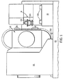
- the controllable tooling of the present invention was developed for the type of machine shown in Figure 1.
- This type of gear cutting machine is designed to cut spur or helical gears through the engagement of a series of stock-removing tools with a workpiece as the tools are advanced about the circumference of a relatively large machining head.
- a number of stock-removing tools are carried on individual link members of an endless chain assembly which extends around the entire machining head portion of the machine, and in this manner, a great number of stock-removing tools can be brought into engagement with a workpiece.
- FIG. 1 Considering the specific details of the machine shown in Figure 1, it can be seen that basic machine assemblies are carried on a common base 10, and these components include a tool carrying assembly 12 mounted on a housing 14 together with a work station 16 mounted on its own base 18.
- the tool carrying assembly 12 can be advanced towards and away from a workpiece 20 through a sliding action of the housing 14 on ways 22.
- the workpiece 20 is mounted on a work spindle 24 for timed rotation or incremental rotation in relationship to the advancement of stock-removing tools 26.
- the illustrated stock-removing tools may be of any known design. In a specific use of this invention, tools of the type in which the cutting face is not resharpened (as shown in U.S. Patent 4,060,881) were used.
- Transverse placement of the workpiece relative to the cutting tools can be achieved through a movement of the work station 16 on ways 28 mounted on the base 18.
- the type of machine just described provides for an engagement of the cutting head portion of the machine with a workblank contained within the work station portion of the machine.
- tooth slots are formed in precisely spaced positions about the circumference of the workpiece to thereby form a spur or helical gear, depending upon the relative tilt of the tool carrying assembly 12 to the workpiece.
- Individual profiles are formed by a generating action between the cutting tools and the workpiece as the tools are brought into full depth engagement with the workpiece and as the workpiece is precisely rotated relative to the cutting tools.
- tooth slots and tooth profiles are formed about the entire circumference of a workblank.
- tooth slots 30 which have sidewalls 32 having no crowning curvature from one face of the gear to an opposite face of the gear. This results from the sequential entry of a series of cutting tools at one end of the tooth slot, followed by a straight line movement of the cutting tools through the tooth slot until the tools leave the slot at an opposite side of the gear.
- Figure 2 also illustrates (with dashed lines) a type of "crowning" curvature which is sometimes desirable for tooth profiles of spur or helical gears.
- crowning is greatly exaggerated in the Figure 2 view (for purpose of clarity), it can be appreciated that even a very mild amount of lengthwise curvature of the tooth slot requires a repositioning of individual cutting tools as they pass through the tooth slot.
- Figure 3 One way of achieving such crowning is shown in Figure 3 wherein a single cutting tool 26 is illustrated as engaging a single sidewall 32 of a tooth slot 30.
- the tooth slot is of a type which is formed to full depth by separate cutting tools of a series which define a bottom for the slot so that the illustrated cutting tool is not required to carry out a dual function of shaping the sidewall 32 as well as the bottom of the tooth slot.
- tooling which cuts side and bottom portions of the tooth slot simultaneously.
- the dashed line position of the wall 32 represents the increased depth of cutting which can be achieved with the cutting tool 26 if the tool is moved in the direction of the arrow. This movement has the effect of removing a greater amount of stock from the sidewall portion of the workpiece.
- Figure 4 shows a number of articulated link members 40 making up the endless chain of the machine of Figure 1.
- the individual link members 40 may be considered as carriers for a series of cutting tools 26 which are arranged in a single row about the entire circumference of the endless chain.
- endless chain type machines are shown in the U.S. Patents 1,468,393 and 1,469,602.
- every other cutting tool 26 of the series is arranged to be axially controlled in its position relative to the carrier 40 with which it is associated. Tools which are not so controlled are fixed in their relationship to the carrier and serve, for example, to rough out a tooth slot or to define the full depth bottom portion of the slot, leaving it to the remaining controllable tools to shape the sidewall portions thereof.
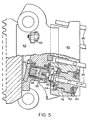
- each of the controllable tools is secured within a mounting means 50 which comprises a mounting block having an exterior profile made up of cylindrical surfaces for being fitted within a bore 52 formed in the carrier.
- the mounting block 50 is suspended within the bore with a pair of spring elements 54 which comprise metallic, flat, ring elements fitted around opposite ends of the mounting block and within the bore of the carrier to provide for a secure suspension of the mounting block within the bore.
- springs serve to constrain the tool radially while, at the same time, permitting limited (on the order of 0.001 to 0.005 inches [approx. 25-125 um.1) axial movement of the tool.
- the spring elements 54 are placed at right angles to the intended line of travel of the tool, thus assuring accurate linear movement of the tool with no deviation from its intended path of travel.
- the spring elements 54 are flexed away from their normal positions shown in Figure 5, and there is a tendency for the mounting block to be returned to its normal position as soon as it is released from a displaced position.
- the mounting block 50 is contacted and moved by a separate displaceable member 55.
- the displaceable member 55 is of a generally cylindrical form and is fitted within a separate portion of the link member 40 so that it does not have to be removed from the link when the tool holder portion 42 is removed for changing or adjusting tools.
- the displaceable member 55 is mounted within a pair of sleeves having roller bearings 56 therebetween, and a hardened end portion 58 is provided for making actual contact with a similarly hardened end portion 60 of the mounting block 50.
- the mounting block 50 is, in turn, advanced and retracted relative to a workpiece.
- Control of the displaceable member 55 is achieved through the use of a control bar 62 (see also Figure 6) having an inclined surface 64 for contacting a portion of the displaceable member 55.
- a control bar 62 see also Figure 6
- transverse movements of the control bar 62 as determined by a cam 66 and a follower 68 carried at the end of the control bar dictate movement of the displaceable member 55 and the mounting block 50 with its contained cutting blade 26.
- the control bar 62 is fitted transversely through a portion of the carrier 40 with its follower being carried externally thereof for contacting a cam surface 66 arranged along the side of the machine housing in which the endless chain is mounted for movement.
- the shape of the profile of the cam surface 66 determines the precise point at which shaping begins and ends in any tooth slot of a workpiece being formed by the cutting tools being carried by the endless chain.
- the working end of the control bar 62 including the inclined surface 64 formed thereon, is mounted on bearings for ease of operation.
- the control bar 62 is loaded against a spring 69 which is arranged to maintain the follower 68 of the control bar in contact with the cam surface 66.
- Figure 6 also shows details for the securement of individual cutting blades 26 into respective mounting blocks 50 with screw fasteners 70.
- a key element 72 which serves to engage a slot formed in a cylindrical portion of the mounting block 50 to prevent rotation of the mounting block (and its contained cutting tool) within the carrier in which it is mounted.
Landscapes
- Engineering & Computer Science (AREA)
- Mechanical Engineering (AREA)
- Gear Processing (AREA)
- Confectionery (AREA)
Abstract
Description
- It is known in the art of gear cutting to provide for machines which utilize an endless chain for carrying a series of cutting tools into engagement with a workpiece to shape the workpiece into a gear form. It is also known to arrange a series of cutting tools around a cylindrical body for forming gears.
- Although existing gear cutting equipment does a very satisfactory job of shaping gear tooth profiles, such as those required for spur and helical gears, certain gear applications require a refinement of such equipment to provide a lengthwise "crowning" of individual tooth members of whatever gear is being manufactured. Crowning is a known feature of certain types of bevel gear making machinery (as shown, for example, in U.S. Patents 2,352,689; 2,385,330; and 2,385,331). When a series of cutting tools are rigidly secured in one or more carriers which are advanced into engagement with a workblank, a generally straight cut is formed when viewed in the longitudinal (or lengthwise) direction of each tooth slot being shaped into the workpiece. In order to crown the side wall portions of such a straight cut, it is required that there be a deeper cut at the entry and exit ends of the tooth slot as a cutting tool advances into and out of the slot. It is a primary purpose of this invention to provide an improved mechanical arrangement for controlling positions of selected cutting tools as they advance through tooth slots of a workpiece to thereby provide for a desired depth of cut to thereby achieve crowning of the individual tooth profiles.
- In US Patent 4140042 a stock-removing tool of a gear cutting machine is held by a carrier which can be advanced into engagement with a workpiece to form tooth slots for a spur or helical gear. Mounting means are provided for the tool for controlled movements relative to its carrier to thereby provide for precision cutting and shaping of gear tooth profiles as the tool is advanced through slots of the workpiece. Control means are associated with the carrier for controlling the positions of the mounting means relative to the carrier in a way which extends or retracts the tool during a cutting operation as the tool is brought into engagement with the workpiece. The mounting means comprises a mounting block for receiving a stock-removing tool in fixed relationship thereto. In the present invention, the mounting block is suspended in a novel way within a bore of an associated carrier with annular spring elements preferably flat ring elements which are fitted around the mounting block and within the bore of the carrier. The spring elements are preferably arranged in parallel planes at right angles to the desired axis of motion for the tool(s). The use of such spring elements eliminates the need for bearings or bearing surfaces and provides for radial rigidity of the tool while permitting linear motion of the tool. In addition, this type of suspension of a tool provides for a more rapid response with less of a tendency to stick initially and then slip to a new position and allows for individual control of separate, selected tools. Preferably a displaceable member is fitted within the carrier for contacting and moving the mounting means in accordance with the degree and type of precision shaping required, and each displaceable member is actuated, in turn, by a control bar which follows a cam surface provided on a relatively fixed portion of the gear machine. In this way controlled movements are dictated to the selected tools as the tools move through a work zone of the machine.
- A mechanism embodying the present invention can be very reliable in design and can provide for a positive and known displacement of the selected cutting tools at exactly the right points of travel of each tool relative to a tooth slot of the workpiece. The use of spring elements for suspending the tools provides for a simple and highly reliable system for positioning and moving the tools. Individual components of the mechanism should be designed to withstand the stresses and workloads associated with production manufacture of gears or similar type products. An embodiment of the invention given by way of example, will now be described with reference to the accompanying drawings in which:
- Figure 1 is an elevational view of a gear cutting machine embodying the present invention;
- Figure 2 is a schematic view of desirable "crowned" tooth profiles;
- Figure 3 is a schematic view of a single cutting tool moving through a tooth slot of a gear blank;
- Figure 4 is an enlarged elevational view, partly in cross-section, of the machine of Figure 1, showing a number of articulated link members for carrying the stock-removing tools of the machine;
- Figure 5 is a greatly enlarged view, partly in cross-section, of a single link member of the machine of Figure 1, showing details of the tool adjusting mechanism;
- Figure 6 is a sectional view taken in a plane at right angles to the view shown in Figure 5; and
- Figure 7 is a view of a cam and follower, as seen on line 7-7 of Figure 6.
- The controllable tooling of the present invention was developed for the type of machine shown in Figure 1. This type of gear cutting machine is designed to cut spur or helical gears through the engagement of a series of stock-removing tools with a workpiece as the tools are advanced about the circumference of a relatively large machining head. In a machine of this type, a number of stock-removing tools are carried on individual link members of an endless chain assembly which extends around the entire machining head portion of the machine, and in this manner, a great number of stock-removing tools can be brought into engagement with a workpiece.
- Considering the specific details of the machine shown in Figure 1, it can be seen that basic machine assemblies are carried on a
common base 10, and these components include a tool carrying assembly 12 mounted on ahousing 14 together with awork station 16 mounted on itsown base 18. The tool carrying assembly 12 can be advanced towards and away from aworkpiece 20 through a sliding action of thehousing 14 onways 22. Theworkpiece 20 is mounted on awork spindle 24 for timed rotation or incremental rotation in relationship to the advancement of stock-removingtools 26. The illustrated stock-removing tools may be of any known design. In a specific use of this invention, tools of the type in which the cutting face is not resharpened (as shown in U.S. Patent 4,060,881) were used. - Transverse placement of the workpiece relative to the cutting tools can be achieved through a movement of the
work station 16 onways 28 mounted on thebase 18. - In operation, the type of machine just described provides for an engagement of the cutting head portion of the machine with a workblank contained within the work station portion of the machine. As the cutting tools engage the workpiece, tooth slots are formed in precisely spaced positions about the circumference of the workpiece to thereby form a spur or helical gear, depending upon the relative tilt of the tool carrying assembly 12 to the workpiece. Individual profiles are formed by a generating action between the cutting tools and the workpiece as the tools are brought into full depth engagement with the workpiece and as the workpiece is precisely rotated relative to the cutting tools. After a single tooth slot has been formed, the cutting tools of the machine are retracted out of engagement with the workpiece, and the workpiece is indexed to a position for forming a next adjacent tooth slot to the one just formed. In this manner, tooth slots and tooth profiles are formed about the entire circumference of a workblank.
- As shown in Figure 2, the normal action of the machine operation just described is to produce
tooth slots 30 which havesidewalls 32 having no crowning curvature from one face of the gear to an opposite face of the gear. This results from the sequential entry of a series of cutting tools at one end of the tooth slot, followed by a straight line movement of the cutting tools through the tooth slot until the tools leave the slot at an opposite side of the gear. - Figure 2 also illustrates (with dashed lines) a type of "crowning" curvature which is sometimes desirable for tooth profiles of spur or helical gears. Although the crowning is greatly exaggerated in the Figure 2 view (for purpose of clarity), it can be appreciated that even a very mild amount of lengthwise curvature of the tooth slot requires a repositioning of individual cutting tools as they pass through the tooth slot. One way of achieving such crowning is shown in Figure 3 wherein a
single cutting tool 26 is illustrated as engaging asingle sidewall 32 of atooth slot 30. As can be seen, the tooth slot is of a type which is formed to full depth by separate cutting tools of a series which define a bottom for the slot so that the illustrated cutting tool is not required to carry out a dual function of shaping thesidewall 32 as well as the bottom of the tooth slot. However, it is possible to use tooling which cuts side and bottom portions of the tooth slot simultaneously. The dashed line position of thewall 32, as shown in Figure 3, represents the increased depth of cutting which can be achieved with thecutting tool 26 if the tool is moved in the direction of the arrow. This movement has the effect of removing a greater amount of stock from the sidewall portion of the workpiece. Thus, it can be seen that such a movement of the cutting tool during the initial part of its travel through a tooth slot and again upon leaving the tooth slot will produce the type of curved shape shown by the dashed lines in the Figure 2 view. Such movement is very precise and very slight and requires a high degree of control of position of the tool as the tool progresses through a tooth slot of a workpiece. This control is achieved with the mechanisms described in Figures 4-7. - Figure 4 shows a number of articulated
link members 40 making up the endless chain of the machine of Figure 1. Theindividual link members 40 may be considered as carriers for a series ofcutting tools 26 which are arranged in a single row about the entire circumference of the endless chain. The manner in which the links are driven and other details of the operation of the machine itself are now known in the art. In addition, endless chain type machines are shown in the U.S. Patents 1,468,393 and 1,469,602. In the arrangement shown in Figure 4, everyother cutting tool 26 of the series is arranged to be axially controlled in its position relative to thecarrier 40 with which it is associated. Tools which are not so controlled are fixed in their relationship to the carrier and serve, for example, to rough out a tooth slot or to define the full depth bottom portion of the slot, leaving it to the remaining controllable tools to shape the sidewall portions thereof. - Referring to Figures 5 and 6, it can be seen that each of the controllable tools is secured within a
mounting means 50 which comprises a mounting block having an exterior profile made up of cylindrical surfaces for being fitted within abore 52 formed in the carrier. Themounting block 50 is suspended within the bore with a pair ofspring elements 54 which comprise metallic, flat, ring elements fitted around opposite ends of the mounting block and within the bore of the carrier to provide for a secure suspension of the mounting block within the bore. These springs serve to constrain the tool radially while, at the same time, permitting limited (on the order of 0.001 to 0.005 inches [approx. 25-125 um.1) axial movement of the tool. This arrangement is simple and reliable and eliminates the need for fitting the tool within bearing surfaces since there is no functional engagement of the tool with the mounting block or with the carrier. Thespring elements 54 are placed at right angles to the intended line of travel of the tool, thus assuring accurate linear movement of the tool with no deviation from its intended path of travel. As the mounting block is moved (in axial directions along the axis of the cutting tool 26), thespring elements 54 are flexed away from their normal positions shown in Figure 5, and there is a tendency for the mounting block to be returned to its normal position as soon as it is released from a displaced position. The mountingblock 50 is contacted and moved by a separatedisplaceable member 55. Thedisplaceable member 55 is of a generally cylindrical form and is fitted within a separate portion of thelink member 40 so that it does not have to be removed from the link when thetool holder portion 42 is removed for changing or adjusting tools. Thedisplaceable member 55 is mounted within a pair of sleeves havingroller bearings 56 therebetween, and ahardened end portion 58 is provided for making actual contact with a similarlyhardened end portion 60 of the mountingblock 50. Thus, as thedisplaceable member 55 is moved toward and away from the mountingblock 50, the mountingblock 50 is, in turn, advanced and retracted relative to a workpiece. - Control of the
displaceable member 55 is achieved through the use of a control bar 62 (see also Figure 6) having aninclined surface 64 for contacting a portion of thedisplaceable member 55. As can be seen from the views of Figures 6 and 7, transverse movements of thecontrol bar 62, as determined by acam 66 and afollower 68 carried at the end of the control bar dictate movement of thedisplaceable member 55 and the mountingblock 50 with itscontained cutting blade 26. It can be seen that thecontrol bar 62 is fitted transversely through a portion of thecarrier 40 with its follower being carried externally thereof for contacting acam surface 66 arranged along the side of the machine housing in which the endless chain is mounted for movement. The shape of the profile of thecam surface 66 determines the precise point at which shaping begins and ends in any tooth slot of a workpiece being formed by the cutting tools being carried by the endless chain. The working end of thecontrol bar 62, including theinclined surface 64 formed thereon, is mounted on bearings for ease of operation. Thecontrol bar 62 is loaded against aspring 69 which is arranged to maintain thefollower 68 of the control bar in contact with thecam surface 66. - Figure 6 also shows details for the securement of
individual cutting blades 26 into respective mountingblocks 50 withscrew fasteners 70. In addition there is shown akey element 72 which serves to engage a slot formed in a cylindrical portion of the mountingblock 50 to prevent rotation of the mounting block (and its contained cutting tool) within the carrier in which it is mounted. - Having described structural features and detail of a specific and preferred embodiment of the present invention, it can be appreciated that the cutting tools which are shown could just as well be grinding elements.
Claims (9)
Applications Claiming Priority (2)
| Application Number | Priority Date | Filing Date | Title |
|---|---|---|---|
| US06/044,807 US4264248A (en) | 1979-06-01 | 1979-06-01 | Controllable tooling for gear cutting machine |
| US44807 | 1979-06-01 |
Publications (3)
| Publication Number | Publication Date |
|---|---|
| EP0029032A1 EP0029032A1 (en) | 1981-05-27 |
| EP0029032A4 EP0029032A4 (en) | 1981-10-27 |
| EP0029032B1 true EP0029032B1 (en) | 1983-11-23 |
Family
ID=21934441
Family Applications (1)
| Application Number | Title | Priority Date | Filing Date |
|---|---|---|---|
| EP80900321A Expired EP0029032B1 (en) | 1979-06-01 | 1980-12-15 | Controllable tooling for gear cutting machine |
Country Status (6)
| Country | Link |
|---|---|
| US (1) | US4264248A (en) |
| EP (1) | EP0029032B1 (en) |
| JP (2) | JPS56500002U (en) |
| CA (1) | CA1127897A (en) |
| DE (1) | DE3065645D1 (en) |
| WO (1) | WO1980002661A1 (en) |
Citations (1)
| Publication number | Priority date | Publication date | Assignee | Title |
|---|---|---|---|---|
| US2749804A (en) * | 1951-06-22 | 1956-06-12 | Daout Robert Nicolas | Device for cutting gear teeth and grooves or splines by the generating process |
Family Cites Families (21)
| Publication number | Priority date | Publication date | Assignee | Title |
|---|---|---|---|---|
| US1469602A (en) * | 1921-06-29 | 1923-10-02 | Perkins Appliance Company | Machine for and method of broaching gears |
| US1737217A (en) * | 1925-04-24 | 1929-11-26 | Barber Colman Co | Gear-cutting machine |
| US2352689A (en) * | 1939-10-18 | 1944-07-04 | Gleason Works | Gear-cutting machine |
| US2346867A (en) * | 1940-10-29 | 1944-04-18 | Michigan Tool Co | Machine for forming gears |
| US2374901A (en) * | 1941-01-21 | 1945-05-01 | Michigan Tool Co | Gear forming machine |
| US2329541A (en) * | 1941-06-18 | 1943-09-14 | Gen Electric | Electric measuring apparatus |
| US2385331A (en) * | 1941-08-02 | 1945-09-25 | Gleason Works | Machine for producing gears |
| US2385330A (en) * | 1944-03-23 | 1945-09-25 | Gleason Works | Machine for cutting gears |
| US2638036A (en) * | 1945-03-02 | 1953-05-12 | Fellows Gear Shaper Co | Double-acting gear shaping machine |
| US2678587A (en) * | 1949-04-18 | 1954-05-18 | Fellows Gear Shaper Co | Apparatus for shaper cutting gears |
| US3096685A (en) * | 1958-07-21 | 1963-07-09 | Maag Zahnraeder & Maschinen Ag | Device for machining the flanks of spur and melical gears |
| US3243863A (en) * | 1963-12-27 | 1966-04-05 | Michigan Tool Co | Cutting tool |
| US3417510A (en) * | 1965-05-10 | 1968-12-24 | Wildhaber Ernest | Method and means for crowning teeth |
| US3459103A (en) * | 1967-10-20 | 1969-08-05 | Michigan Tool Co | Tool guide for gear forming machine |
| US3587385A (en) * | 1967-11-09 | 1971-06-28 | Voitk Getriehe Kg | Cutter head |
| US3508462A (en) * | 1968-09-03 | 1970-04-28 | Ernest Wildhaber | Method and means for producing teeth and lobes |
| US3659496A (en) * | 1970-03-13 | 1972-05-02 | Gleason Works | Machine for shaping gears |
| DE2139737C3 (en) * | 1971-08-07 | 1975-02-27 | Zahnradfabrik Friedrichshafen Ag, 7990 Friedrichshafen | Tool for front-side deburring of gears with automatically adjustable deburring knife according to the inclination of the front side |
| SU523762A1 (en) * | 1974-12-30 | 1976-08-05 | Московский Станкозавод Им. Серго Орджоникидзе | Cutter Mounting Device |
| CH608980A5 (en) * | 1976-05-17 | 1979-02-15 | Maag Zahnraeder & Maschinen Ag | |
| CH624325A5 (en) * | 1977-12-23 | 1981-07-31 | Maag Zahnraeder & Maschinen Ag |
-
1979
- 1979-06-01 US US06/044,807 patent/US4264248A/en not_active Expired - Lifetime
-
1980
- 1980-01-15 WO PCT/US1980/000032 patent/WO1980002661A1/en not_active Ceased
- 1980-01-15 DE DE8080900321T patent/DE3065645D1/en not_active Expired
- 1980-01-15 JP JP1981600002U patent/JPS56500002U/ja active Pending
- 1980-02-19 CA CA346,111A patent/CA1127897A/en not_active Expired
- 1980-03-03 JP JP50052380A patent/JPS56500002A/ja active Pending
- 1980-12-15 EP EP80900321A patent/EP0029032B1/en not_active Expired
Patent Citations (1)
| Publication number | Priority date | Publication date | Assignee | Title |
|---|---|---|---|---|
| US2749804A (en) * | 1951-06-22 | 1956-06-12 | Daout Robert Nicolas | Device for cutting gear teeth and grooves or splines by the generating process |
Also Published As
| Publication number | Publication date |
|---|---|
| EP0029032A1 (en) | 1981-05-27 |
| WO1980002661A1 (en) | 1980-12-11 |
| EP0029032A4 (en) | 1981-10-27 |
| DE3065645D1 (en) | 1983-12-29 |
| US4264248A (en) | 1981-04-28 |
| JPS56500002A (en) | 1981-01-08 |
| CA1127897A (en) | 1982-07-20 |
| JPS56500002U (en) | 1981-05-07 |
Similar Documents
| Publication | Publication Date | Title |
|---|---|---|
| EP0212860B1 (en) | Disposable disk cutter | |
| US4404878A (en) | Bar stock feed apparatus | |
| KR100293616B1 (en) | How to manufacture helical bevel gears and hypoid gears and surface hobbing type cutter for manufacturing said gears | |
| CA1313786C (en) | Indexing device | |
| US4264248A (en) | Controllable tooling for gear cutting machine | |
| EP0311182B1 (en) | Method of manufacturing a master for the fabrication of projection screens and tool for carrying out the method | |
| US5396818A (en) | Method of making a wafer broaching tool | |
| PL125279B1 (en) | Apparatus for forming heads at ends of rod-like workpieces in particular heads of nails or screws | |
| US3823626A (en) | Method of and apparatus for machining curved surfaces | |
| US3595130A (en) | Gear making | |
| US4189267A (en) | Clamping means for reducing deflections in machine tool | |
| US3618459A (en) | Gear making | |
| US3618189A (en) | Gear making | |
| RU200452U1 (en) | CUTTING TOOL | |
| SU1085676A1 (en) | Lathe | |
| SU846024A1 (en) | Cone rolling out apparatus | |
| SU1726149A1 (en) | Revolving multi-cutter tool | |
| EP1105240B1 (en) | Three-jaw chuck, a method and a device for cutting teeth of the jaws | |
| CA1088357A (en) | Endless chain apparatus for forming gears | |
| SU1247175A1 (en) | Boring mandrel | |
| RU2064377C1 (en) | Process of formation of teeth of gears with helical gear cutter | |
| GB2099347A (en) | Pressure forming teeth on a cylindrical part | |
| SU1255315A1 (en) | Method of milling spur gear-wheels | |
| SU1016090A1 (en) | Method of machining shaped surfaces of bodies-of-revolution | |
| RU1806048C (en) | Method for cutting rack teeth on end surfaces of self-centering chuck cams |
Legal Events
| Date | Code | Title | Description |
|---|---|---|---|
| PUAI | Public reference made under article 153(3) epc to a published international application that has entered the european phase |
Free format text: ORIGINAL CODE: 0009012 |
|
| AK | Designated contracting states |
Designated state(s): CH DE FR GB |
|
| 17P | Request for examination filed |
Effective date: 19810529 |
|
| RBV | Designated contracting states (corrected) |
Designated state(s): CH DE FR GB |
|
| GRAA | (expected) grant |
Free format text: ORIGINAL CODE: 0009210 |
|
| AK | Designated contracting states |
Designated state(s): CH DE FR GB |
|
| REF | Corresponds to: |
Ref document number: 3065645 Country of ref document: DE Date of ref document: 19831229 |
|
| ET | Fr: translation filed | ||
| PLBE | No opposition filed within time limit |
Free format text: ORIGINAL CODE: 0009261 |
|
| STAA | Information on the status of an ep patent application or granted ep patent |
Free format text: STATUS: NO OPPOSITION FILED WITHIN TIME LIMIT |
|
| 26N | No opposition filed | ||
| PGFP | Annual fee paid to national office [announced via postgrant information from national office to epo] |
Ref country code: GB Payment date: 19891231 Year of fee payment: 11 |
|
| PGFP | Annual fee paid to national office [announced via postgrant information from national office to epo] |
Ref country code: FR Payment date: 19900115 Year of fee payment: 11 |
|
| PGFP | Annual fee paid to national office [announced via postgrant information from national office to epo] |
Ref country code: DE Payment date: 19900125 Year of fee payment: 11 |
|
| PGFP | Annual fee paid to national office [announced via postgrant information from national office to epo] |
Ref country code: CH Payment date: 19900320 Year of fee payment: 11 |
|
| PG25 | Lapsed in a contracting state [announced via postgrant information from national office to epo] |
Ref country code: GB Effective date: 19910115 |
|
| PG25 | Lapsed in a contracting state [announced via postgrant information from national office to epo] |
Ref country code: CH Effective date: 19910131 |
|
| GBPC | Gb: european patent ceased through non-payment of renewal fee | ||
| PG25 | Lapsed in a contracting state [announced via postgrant information from national office to epo] |
Ref country code: FR Effective date: 19910930 |
|
| REG | Reference to a national code |
Ref country code: CH Ref legal event code: PL |
|
| PG25 | Lapsed in a contracting state [announced via postgrant information from national office to epo] |
Ref country code: DE Effective date: 19911001 |
|
| REG | Reference to a national code |
Ref country code: FR Ref legal event code: ST |