EP0028554B1 - Anneaux à joint d'étanchéité refroidi et turbine à gaz équipée d'un tel anneau - Google Patents
Anneaux à joint d'étanchéité refroidi et turbine à gaz équipée d'un tel anneau Download PDFInfo
- Publication number
- EP0028554B1 EP0028554B1 EP80401470A EP80401470A EP0028554B1 EP 0028554 B1 EP0028554 B1 EP 0028554B1 EP 80401470 A EP80401470 A EP 80401470A EP 80401470 A EP80401470 A EP 80401470A EP 0028554 B1 EP0028554 B1 EP 0028554B1
- Authority
- EP
- European Patent Office
- Prior art keywords
- layer
- separating layer
- air
- refrigerant
- wheel
- Prior art date
- Legal status (The legal status is an assumption and is not a legal conclusion. Google has not performed a legal analysis and makes no representation as to the accuracy of the status listed.)
- Expired
Links
- 238000007789 sealing Methods 0.000 title claims description 7
- 239000000463 material Substances 0.000 claims description 19
- 239000007789 gas Substances 0.000 claims description 14
- 230000035699 permeability Effects 0.000 claims description 12
- 238000011144 upstream manufacturing Methods 0.000 claims description 8
- 239000011888 foil Substances 0.000 claims description 6
- 230000009471 action Effects 0.000 claims description 4
- 230000007423 decrease Effects 0.000 claims description 2
- 239000000126 substance Substances 0.000 claims description 2
- 239000003507 refrigerant Substances 0.000 claims 10
- 238000001816 cooling Methods 0.000 description 35
- 239000011148 porous material Substances 0.000 description 7
- 229910045601 alloy Inorganic materials 0.000 description 5
- 239000000956 alloy Substances 0.000 description 5
- 229910000623 nickel–chromium alloy Inorganic materials 0.000 description 3
- 238000007750 plasma spraying Methods 0.000 description 3
- 229910018487 Ni—Cr Inorganic materials 0.000 description 2
- VNNRSPGTAMTISX-UHFFFAOYSA-N chromium nickel Chemical compound [Cr].[Ni] VNNRSPGTAMTISX-UHFFFAOYSA-N 0.000 description 2
- 238000004891 communication Methods 0.000 description 2
- 230000000295 complement effect Effects 0.000 description 2
- 239000002131 composite material Substances 0.000 description 2
- 230000003247 decreasing effect Effects 0.000 description 2
- 238000009792 diffusion process Methods 0.000 description 2
- 238000009826 distribution Methods 0.000 description 2
- 238000003754 machining Methods 0.000 description 2
- 210000003462 vein Anatomy 0.000 description 2
- 240000008042 Zea mays Species 0.000 description 1
- 238000002679 ablation Methods 0.000 description 1
- 239000011324 bead Substances 0.000 description 1
- 238000005219 brazing Methods 0.000 description 1
- 229910010293 ceramic material Inorganic materials 0.000 description 1
- 238000002485 combustion reaction Methods 0.000 description 1
- 238000006073 displacement reaction Methods 0.000 description 1
- 238000010894 electron beam technology Methods 0.000 description 1
- 239000006260 foam Substances 0.000 description 1
- 230000004927 fusion Effects 0.000 description 1
- 238000011065 in-situ storage Methods 0.000 description 1
- 238000000034 method Methods 0.000 description 1
- 238000003892 spreading Methods 0.000 description 1
- 230000007480 spreading Effects 0.000 description 1
- 238000009827 uniform distribution Methods 0.000 description 1
Images
Classifications
-
- F—MECHANICAL ENGINEERING; LIGHTING; HEATING; WEAPONS; BLASTING
- F01—MACHINES OR ENGINES IN GENERAL; ENGINE PLANTS IN GENERAL; STEAM ENGINES
- F01D—NON-POSITIVE DISPLACEMENT MACHINES OR ENGINES, e.g. STEAM TURBINES
- F01D11/00—Preventing or minimising internal leakage of working-fluid, e.g. between stages
- F01D11/08—Preventing or minimising internal leakage of working-fluid, e.g. between stages for sealing space between rotor blade tips and stator
- F01D11/12—Preventing or minimising internal leakage of working-fluid, e.g. between stages for sealing space between rotor blade tips and stator using a rubstrip, e.g. erodible. deformable or resiliently-biased part
- F01D11/122—Preventing or minimising internal leakage of working-fluid, e.g. between stages for sealing space between rotor blade tips and stator using a rubstrip, e.g. erodible. deformable or resiliently-biased part with erodable or abradable material
-
- F—MECHANICAL ENGINEERING; LIGHTING; HEATING; WEAPONS; BLASTING
- F05—INDEXING SCHEMES RELATING TO ENGINES OR PUMPS IN VARIOUS SUBCLASSES OF CLASSES F01-F04
- F05D—INDEXING SCHEME FOR ASPECTS RELATING TO NON-POSITIVE-DISPLACEMENT MACHINES OR ENGINES, GAS-TURBINES OR JET-PROPULSION PLANTS
- F05D2260/00—Function
- F05D2260/20—Heat transfer, e.g. cooling
- F05D2260/203—Heat transfer, e.g. cooling by transpiration cooling
-
- Y—GENERAL TAGGING OF NEW TECHNOLOGICAL DEVELOPMENTS; GENERAL TAGGING OF CROSS-SECTIONAL TECHNOLOGIES SPANNING OVER SEVERAL SECTIONS OF THE IPC; TECHNICAL SUBJECTS COVERED BY FORMER USPC CROSS-REFERENCE ART COLLECTIONS [XRACs] AND DIGESTS
- Y02—TECHNOLOGIES OR APPLICATIONS FOR MITIGATION OR ADAPTATION AGAINST CLIMATE CHANGE
- Y02T—CLIMATE CHANGE MITIGATION TECHNOLOGIES RELATED TO TRANSPORTATION
- Y02T50/00—Aeronautics or air transport
- Y02T50/60—Efficient propulsion technologies, e.g. for aircraft
-
- Y—GENERAL TAGGING OF NEW TECHNOLOGICAL DEVELOPMENTS; GENERAL TAGGING OF CROSS-SECTIONAL TECHNOLOGIES SPANNING OVER SEVERAL SECTIONS OF THE IPC; TECHNICAL SUBJECTS COVERED BY FORMER USPC CROSS-REFERENCE ART COLLECTIONS [XRACs] AND DIGESTS
- Y10—TECHNICAL SUBJECTS COVERED BY FORMER USPC
- Y10S—TECHNICAL SUBJECTS COVERED BY FORMER USPC CROSS-REFERENCE ART COLLECTIONS [XRACs] AND DIGESTS
- Y10S277/00—Seal for a joint or juncture
- Y10S277/93—Seal including heating or cooling feature
Definitions
- the support ring is shaped so as to provide an annular passage around the distributor layer. Ports in this support ring make it possible to divert a fraction of the compressor air flow to this annular passage.
- the air permeability of the wearing layer is higher than that of the distributing layer which is supposed to distribute the cooling air in a homogeneous way through the wearing layer. The fact that this is more permeable than the distributing layer is supposed to make it possible to maintain the air flow at its initial value even if the machining by the blade tips causes a partial obstruction of the surface pores of the layer of wear.
- Said device further comprising means for admitting air circulating in the first layer.
- the annular layer called "separating layer” is interposed between the two other layers, and is made of a material whose air permeability is such that the radial air flow which passes through this separating layer is substantially less than the flow d axial air which traverses the first layer.
- part of the air flow admitted into the cavity and intended for cooling the ring itself crosses the first layer radially and then feeds the wear layer to be injected into the vein with a direction approximately tangential to the surface of the seal.
- Another part of the cooling air flow escapes through semi-axial channels of the first annular layer.
- this part of the air is not mainly intended for cooling the ring itself.
- the cooled seal ring of the invention is characterized in that intake ports are provided at one end of the shell surrounding the cooling layer and discharge ports are provided at the other end to allow the axial passage of the cooling air through the entire section of the cooling layer, the wear layer being thus essentially cooled by thermal conduction through said separating layer.
- the radial air flow can also be zero, that is to say that the separating layer is sealed.
- the low air flow possibly passing through the separating layer we see that it is cooled both by forced convention of the air flowing in contact with it and by thermal conduction to the cooling layer, itself energetically cooled by forced convection.
- the wear layer it is mainly cooled by conduction to the separating layer.
- the air permeability of the cooling layer can in particular be as high as it is desirable, without having to worry about the permeability of the wear layer.
- the cooling is not affected by a partial clogging of the wear layer.
- the separating layer is produced by plasma spraying, when this layer is obtained, the operation is continued with a different setting of the torch, which gives the wear material a porosity different from that of the separating layer although 'it is the same material.
- the wear layer is made of a ceramic material, the separating layer applied to the torch would constitute the anchor layer of the wear material. The cooling action of the air passing through the wear layer thus completes that of the cooling layer and the separating layer can be given a decreasing permeability from upstream to downstream so as to obtain a uniform distribution of the flow. radial despite the variation in gas pressure at the wheel passage.
- the separating layer acting by conduction and not by thermal diffusion it is advantageous to make it as thin as possible, to an extent compatible with the possibilities of realization and the requirements of mechanical strength.
- To promote the cooling of the wear layer it is also advantageous to make it as thin as possible to the extent compatible with the deformations of the rotor due to differential expansions and to low imbalances caused by normal operation.
- the separating layer is appreciably thinner than the wear layer, itself appreciably thinner than the cooling layer.
- the seal is then formed by the wear layer proper, but, in the event of significant radial displacement of the wheel (for example in the case of a significant unbalance caused by the rupture of a dawn), the cooling layer also plays a complementary role as a reserve wear layer compared to the normal wear layer.
- the total thickness of the composite layer formed by the juxtaposition of the three elementary layers is not greater than the thickness of a wear layer of the prior art.
- the blade tips such as 91 machine the surface of the wear layer 23, so that at rest a clearance J remains between this layer and said blade ends.
- the upstream crown 12 projects around the outer wall of the ferrule 11.
- a circular housing 15 which covers an annular bead 32 secured to a web 31 itself linked to the casing of the turbine. This is not shown.
- the outer wall of the shell 10 carries downstream, at a determined distance upstream of the ring 13, an external ring 16 which supports an annular flange 17 which projects downstream.
- This crown 16 and the flange 17 are inserted into the circular orifice of a web 33 also linked to the casing of the turbine.
- This veil 33 carries an annular flange 34 which surrounds the flange 17.
- An elastic fixing ring 35 with a current U-shaped section makes it possible to pinch the flanges 17 and 34 against one another to secure the support ring 10.
- the two sails 31 and 33 define an E1 space. Behind the veil 33 there is a space E2 delimited by the veil 33, the turbine casing or any other known means.
- the space E1 is supplied with cooling air coming from the compressor, not shown.
- the space E2 communicates with the gas stream downstream of the wheel.
- the space E1 is therefore in overpressure with respect to the space E2.
- Air intake orifices such as 18 are provided in the shell 11 immediately downstream of the ring 14 and put the cooling layer 21 and the space E1 into communication.
- Air discharge orifices such as 19 are formed in said ferrule 11 downstream of the ring 16 and put said cooling layer 21 and the space E2 into communication.
- a flow of cooling air thus traverses the layer 21 from upstream to downstream, that is to say in an axial direction.
- the separating layer 22 is cooled by convection, thanks to contact with the air flow, also and above all by conduction, thanks to contact with the cooling layer 21 itself cooled by air. It will be noted that the layers 21 and 22 cooperate to form an antithermal screen protecting the shell 10 against the heat of the gases passing through the wheel.
- the orifices 19 formed in the shell 11 can be replaced by orifices formed in the crown 13, such as the orifice 19 'shown in dotted lines.
- the crown 16 can then be moved downstream, in the position 16 ′, that is to say in line with the crown 13.
- the device of Figure 1 further comprises the three additional advantageous arrangements which will be described below.
- the first of these arrangements consists in giving the separating layer 22 a certain air permeability, for example with a view to cooling the wear layer 23 not only by conduction but also by convection.
- this permeability remains such that the radial air flow flowing through layers 22 and 23 is substantially less than the axial air flow passing through layer 21.
- the second complementary arrangement consists in inserting deflectors in the cooling layer 21 in order to increase the heat exchanges between the air and said layer to improve the cooling of the latter.
- deflectors consist of crown-shaped sails 25 and 26 alternately inserted in the layer 21.
- the sails 25 have an outside diameter equal to the inside diameter of the shell 11 and an inside diameter substantially greater than the outside diameter of the separating layer. 22.
- the sails 26 have an outside diameter substantially smaller than the inside diameter of the shell 11 and an inside diameter equal to the outside diameter of the separating layer 22. In addition to their function of deflectors, the sails 26 also act as radiators favoring the heat removal from said layer 22.
- a third additional arrangement consists in constituting the cooling layer 21 and the separating layer 22 in materials capable of being machined by the paddle ends 91. It makes it possible to reduce the thickness of the wear layer 23 to the minimum compatible with operation of the turbine under suitable conditions. In the event of a very large unbalance, due for example to the rupture of one or more blades, the ends of the remaining blades 91 trace their path in the layer 21, for example at 91 ′. It is thus possible to confer on the composite layer formed by the assembly of the three elementary layers 21, 22 and 23, a total thickness which does not exceed the thickness of a layer of sealing gasket of the prior art. If sails 25 and 26 are present, the sails 26 must then also be made of a material capable of being machined by the ends of the blades.
- the cooling layer 21 is brazed on the shell 11 and is formed by a foam or a sintered material made of a nickel-chromium-based alloy.
- the separating layer 22 can be produced by means of a foil (perforated or not) made of ductile alloy, for example a nickel-chromium alloy, brazed on the layer 21, or also by plasma spraying of an alloy, for example nickel-chrome base.
- the material of the wear layer 23 can for example be a refractory felt of a nickel-chromium base alloy bonded by brazing and diffusion to the separating layer 22 o further deposit of nickel-chromium alloy produced by plasma spraying.
- the separating layer and the wear layer may be made of the same material but of a different module.
- the sails 25 are made of nickel-chrome alloy foil and are brazed to the ferrule 11. As for the sails 26, they are produced "in situ” by machining grooves in the cooling layer 21 and by recharging these grooves by means of '' a deposit of nickel-chromium alloy by plasma torch.
- the webs 26 can also be produced by fusion, for example by bombardment with electron beams.
Landscapes
- Engineering & Computer Science (AREA)
- Mechanical Engineering (AREA)
- General Engineering & Computer Science (AREA)
- Turbine Rotor Nozzle Sealing (AREA)
Description
- L'invention est relative aux turbines à gaz et notamment aux turbines à gaz de turboréacteurs aéronautiques. Elle concerne plus spécialement un anneau à joint d'étanchéité à disposer autour d'une roue de turbine à gaz pour limiter les fuites de gaz au droit des extrémités des aubes. D'une façon générale, le refroidissement des organes de turbine en contact avec les gaz moteurs permet d'accroître la température de combustion et par conséquent la puissance et le rendement du turboréacteur. En ce qui concerne les joints d'étanchéité en matériau susceptible d'être usiné par l'extrémité des aubes, on a déjà proposé de les refroidir par circulation forcée d'une fraction du débit d'air délivré par le compresseur au travers de pores ou d'interstices dudit matériau. Le brevet américain n° 3 825 364 décrit par exemple un anneau à joint d'étanchéité qui comporte en succession, de la périphérie vers l'axe:
- a) un anneau-support disposé autour de la roue,
- b) une première couche annulaire (que l'on dénommera pour l'instant »couche distributrice«) accrochée à cet anneau-support et faite d'un matériau perméable à l'air,
- c) une deuxième couche annulaire (que l'on dénommera »couche d'usure«) fixée à l'intérieur de la couche distributrice, venant à proximité immédiate des extrémités des aubes de la roue et faite d'un matériau poreux à pores ouverts, usinable par ces extrémités d'aubes et insensible à l'action thermique et chimique des gaz actionnant la roue.
- L'anneau-support est conformé de façon à ménager autour de la couche distributrice un passage annulaire. Des orifices ménagés dans cet anneau-support permettent de dériver vers ce passage annulaire une fraction du débit d'air du compresseur. La perméabilité à l'air de la couche d'usure est supérieure à celle de la couche distributrice qui est censée distribuer l'air de refroidissement d'une façon homogène au travers de la couche d'usure. Le fait que celle-ci soit plus perméable que la couche distributrice est censé permettre de maintenir le débit d'air à sa valeur initiale même si l'usinage par les extrémités d'aubes provoque une obstruction partielle des pores superficels de la couche d'usure.
- Ce procédé de refroidissement de la couche d'usure par ciculation d'air au travers de celle-ci présente en fait des inconvénients notables qui font que le dispositif de l'art antérieur ci-dessus décrit n'atteint que partiellement son objet. En effet,
- - pour que l'air s'écoule avec un débit suffisant malgré la pression régnant dans la veine, il faut qu'il soit admis autour de la couche distributrice sous une pression relativement élevée (par exemple de l'ordre de 15 bars), ce qui affecte les performances du turboréacteur;
- - en raison des variations de la pression des gaz durant la traversée de la roue, la répartition du débit d'air au travers de la couche d'usure n'est pas aussi homogène qu'on pourrait l'escompter; l'air se déplace dans la couche non seulement radialement (c'est-à-dire transversalement à la couche) mais aussi axialcment (c'est-à-dire parallèlement à l'axe de la roue) et l'écoulement axial contrarie l'écoulement radial;
- - bien que, lorsque le joint est neuf, la perméabilité de la couche d'usure soit plus grande que celle de la couche ditributrice, les pores ou interstices superficiels de la couche d'usure s'obstruent plus ou moins à la longue, par pollution et par »tartinage«, et le débit d'air de refroidissement risque de décroître de façon dangereuse;
- - les choix des caractéristiques des deux couches sont étroitement liés car l'air de refroidissement les traverse toutes les deux maisson débit doit demeurer limité par la couche réfrigérante; ces choix résultent d'un compromis;
- - enfin, le joint est plus épais que les joints de l'art antérieur du fait qu'à l'épaisseur de la couche d'usure s'ajoute celle de la couche distributrice et que celle-ci doit être suffisamment épaisse pour jouer son rôle de distributeur d'air.
- De plus, le US-A-3 719 365 décrit un anneau à joint d'étanchéité pour roue de turbine dans lequel on trouve successivement de l'extérieur vers l'intérieur,
- - un anneau support,
- - une première couche annulaire percée de canaux radiaux,
- - une couche séparatrice,
- - et une couche d'usure percée de canaux fortement inclinés.
- Ledit dispositif comportant d'autre part, des moyens d'admettre de l'air circulant dans la première couche.
- La couche annulaire dite »couche séparatrice« est intercalée entre les deux autres couches, et est faite d'un matériau dont la perméabilité à l'air est telle que le débit d'air radial qui traverse cette couche séparatrice est sensiblement inférieur au débit d'air axial qui parcourt la première couche.
- On remarque qui une partie du débit d'air admis dans la cavité et destiné au refroidissement de l'anneau même traverse radialement la première couche puis alimente la couche d'usure pour être injecté dans la veine avec une direction approximativement tangentielle à la surface de la garniture d'étanchéité. Une autre partie du débit de l'air de refroidissement s'échappe par des canaux semi-axiaux de la première couche annulaire. Cependant, cette partie de l'air n'est pas principalement destinée au refroidissement de l'anneau même.
- L'anneau à joint d'étanchéité refroidi de l'invention est caractérisé en ce que des orifices d'admission sont ménagés à l'une extrémité de la virole entourant la couche réfrigérante et des orifices d'évacuation sont ménagés à l'autre extrémité pour permettre le passage axial de l'air réfrigérant au travers de toute la section de la couche réfrigérante, la couche d'usure étant ainsi essentiellement refroidie par conduction thermique au travers de ladite couche séparatrice.
- Dans beaucoup de cas d'utilisation, le débit d'air radial peut d'ailleurs être nul, c'est-à-dire que la couche séparatrice est étanche.
- Si l'on néglige, en première approximation, le faible débit d'air traversant éventuellement la couche séparatrice, on constate que celle-ci est refroidie à la fois par convention forcée de l'air circulant à son contact et par conduction thermique vers la couche réfrigérante, elle-même refroidie énergiquement par convection forcée. Quant à la couche d'usure elle est surtout refroidie par conduction vers la couche séparatrice. La perméabilité à l'air de la couche réfrigérante peut notamment être aussi grande qu'il est désirable, sans avoir à se soucier de la perméabilité de la couche d'usure. En outre, le refroidissement n'est pas affecté par un colmatage partiel de la couche d'usure.
- On peut, comme on l'a déjà indiqué, utiliser une couche séparatrice totalement imperméable à l'air (en la constituant par exemple par un clinquant) ou laisser une certaine perméabilité (clinquant perforé). Dans le cas où la couche séparatrice est réalisée par projection au plasma, lorsque cette couche est obtenue on continue l'opération avec un réglage différent du chalumeau, ce qui confère au matériau d'usure une porosité différente de celle de la couche séparatrice bien qu'il s'agisse du même matériau. Lorsque la couche d'usure est constituée d'un matériau céramique, la couche séparatrice appliquée au chalumeau constituerait la couche d'ancrage du matériau d'usure. L'action refroi- dissante de l'air traversant la couche d'usure complète ainsi celle de la couche réfrigérante et l'on peut conférer à la couche séparatrice une perméabilité décroissante d'amont en aval de façon à obtenir une répartition homogène du débit radial malgré la variation de pression des gaz au passage de la roue.
- La couche séparatrice agissant par conduction et non pas par diffusion thermique, il est intéressant de la rendre aussi mince que possible, dans une mesure compatible avec les possibilités de réalisation et les nécessités de tenue mécanique. Pour favoriser le refroidissement de la couche d'usure, on a également intérêt à rendre celle-ci aussi mince que possible dans la mesure compatible avec les déformations du rotor dues aux dilatations différentielles et aux faibles balourds provoqués par un fonctionnement normal. Ainsi, la couche séparatrice est sensiblement moins épaisse que la couche d'usure, elle-même sensiblement moins épaisse que la couche réfrigérante. Mais alors, et toujours dans le cadre de l'invention, il devient avantageux de constituer la couche réfrigérante également d'un matériau susceptible d'être usiné par l'extrémité des aubes et de constituer la couche séparatrice par une lame suffisamment mince et suffisamment ductile pour permettre facilement son ablation par les extrémités des aubes de la roue. En fonctionnement normal, le joint d'étanchéité est alors constitué par la couche d'usure proprement dite, mais, en cas de déplacement radial important de la roue (par exemple dans le cas d'un balourd important provoqué par la rupture d'une aube), la couche réfrigérante joue également un rôle complémentaire de couche d'usure de réserve par rapport à la couche d'usure normale.
- En fin de compte, l'épaisseur totale de la couche composite constituée par la juxtaposition des trois couches élémentaires n'est pas plus grande que l'épaisseur d'une couche d'usure de l'art antérieur.
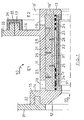
- D'autres dispositions et les avantages qui en découlent seront évoqués dans la description qui suit d'un exemple de réalisation conforme à l'invention, en référence à la figure unique annexée qui représente à grande échelle une coupe radiale d'un dispositif illustrant cet exemple.
- L'anneau-support 10 est disposé au droit de la roue de turbine. On aperçoit une extrémité 91 de l'une des aubes 90 de la roue. L'anneau-support 10 comporte une virole 11, une couronne amont 12 et une couronne aval 13 de telle sorte que sa section radiale forme un logement en U dont les branches sont orientées vers l'axe de la roue et qui contient les trois couches annulaires qui constituent le joint d'étanchéité de l'invention. Ces trois couches sont, de la périphérie vers l'axe:
- - la couche réfrigérante 21, appliquée contre la paroi interne de la virole 11,
- - la couche séparatrice 22, appliquée contre la couche réfrigérante 21,
- - la couche d'usure 23 qui est appliquée contre la couche séparatrice 22 et qui affleure les bords internes des couronnes 12 et 13.
- En fonctionnement normal, les extrémités d'aubes telles que 91 usinent la surface de la couche d'usure 23, ce qui fait qu'au repos un jeu J subsiste entre cette couche et lesdites extrémités d'aubes.
- La couronne amont 12 déborde autour de la paroi externe de la virole 11. Dans la partie débordante 14 est ménagé un logement circulaire 15 qui coiffe un cordon annulaire 32 solidaire d'un voile 31 lui-même lié à l'enveloppe de la turbine. Cette n'est pas représentée.
- La paroi externe de la virole 10 porte en aval, à une distance déterminée en amont de la couronne 13, une couronne externe 16 qui supporte une bride annulaire 17 qui déborde vers l'aval. Cette couronne 16 et la bride 17 s'insèrent dans l'orifice circulaire d'un voile 33 lié aussi à l'enveloppe de la turbine. Ce voile 33 porte une bride annulaire 34 qui entoure la bride 17. Un anneau élastique de fixation 35 à section courante en U permet de pincer l'une contre l'autre les brides 17 et 34 pour assujettir l'anneau-support 10.
- Les deux voiles 31 et 33 délimitent un expace E1. En arrière du voile 33 se trove un espace E2 délimité par le voile 33, le carter de turbine ou tout autre moyen connu. L'espace E1 est alimenté en air de refroidissement venant du compresseur, non représenté. L'espace E2 communique avec la veine de gaz en aval de la roue. L'espace E1 est donc en surpression par rapport à l'espace E2. Des orifices d'admission d'air tels que 18 sont ménagés dans la virole 11 immédiatement en aval de la couronne 14 et mettent en communication la couche réfrigérante 21 et l'espace E1. Des orifices d'évacuation d'air tels que 19 sont ménagés dans ladite virole 11 en aval de la couronne 16 et mettent en communication ladite couche réfrigérante 21 et l'espace E2. Un flux d'air réfrigérant parcourt ainsi la couche 21 d'amont en aval, c'est-à-dire dans une direction axiale. La couche séparatrice 22 est refroidie par convection, grâce au contact avec le flux d'air, aussi et surtout par conduction, grâce au contact avec la couche réfrigérante 21 elle-même refroidie par l'air. On remarquera que les couches 21 et 22 coopèrent pour constituer un écran antithermique protégeant la virole 10 contre la chaleur des gaz traversant la roue.
- Si la couche 21 est suffisamment épaisse, les orifices 19 ménagés dans la virole 11 peuvent être remplacés pai des orifices ménagés dans la couronne 13, tel l'orifice 19' représenté en pointillé. La couronne 16 peut alors être reculée vers l'aval, dans la position 16', c'est-à-dire au droit de la couronne 13.
- Eventuellement, le dispositif de la figure 1 comporte en outre les trois dispositions supplémentaires avantageuses que l'on va décrire ci-après.
- La première de ces dispositions consiste à conférer à la couche séparatrice 22 une certaine perméabilité à l'air, en vue par exemple de refroidir la couche d'usure 23 non seulement par conduction mais aussi par convection. Cette perméabilité demeure cependent telle que le débit d'air radial s'écoulant au travers des couches 22 et 23 est sensiblement inférieur au débit d'air axial parcourant la couche 21. En vue d'assurer une répartition homogène du débit radial malgré la variation de pression des gaz qui se produit au passage de la roue, on peut avantageusement conférer à la couche 22 une perméabilité décroissante d'amont en aval. On a supposé sur la figure unique que la couche 22 est faite d'un matériau étanche. Elle est rendue perméable au moyen d'une pluralité de petits orifices 24 dont la densité, c'est-à-dire le nombre par unité de surface, est plus faible en aval qu'en amont.
- La deusiéme disposition complémentaire consiste à insérer des déflecteurs dans la couche réfrigérante 21 afin d'accroître les échanges thermiques entre l'air et ladite couche pour améliorer le refroidissement de celle-ci. Ces déflecteurs consistent en des voiles en forme de couronne 25 et 26 alternativement insérés dans la couche 21. Les voiles 25 ont un diamètre extérieur égal au diamètre intérieur de la virole 11 et un diamètre intérieur sensiblement plus grand que le diamètre extérieur de la couche séparatrice 22. Les voiles 26 ont un diamètre extérieur sensiblement plus petit que le diamètre intérieur de la virole 11 et un diamètre intérieur égal au diamètre extérieur de la couche séparatrice 22. Outre leur fonction de déflecteurs, les voiles 26 agissent aussi comme radiateurs favorisant l'évacuation de la chaleur de ladite couche 22.
- Une troisième disposition complémentaire consiste à constituer la couche réfrigérante 21 et la couche séparatrice 22 en des matériaux susceptibles d'être usinés par les extrémités s'aubes 91. Elle permet de reduire l'épaisseur de la couche d'usure 23 au minimum compatible avec un fonctionnement de la turbine dans les conditions convenables. En cas d'un balourd très important, dû par exemple à la rupture d'une ou de plusieurs aubes, les extrémités des aubes 91 restantes tracent leur chemin dans la couche 21, par exemple en 91'. On peut ainsi conférer à la couche composite formée par l'assemblage des trois couches élémentaires 21, 22 et 23, une épaisseur totale que ne dépasse pas l'épaisseur d'une couche de joint détanchéité de l'art antérieur. Si des voiles 25 et 26 sont présents, les voiles 26 doivent alors eux aussi être faits d'un matériau susceptible d'être usiné par les extrémités d'aubes.
- On donne ci-»près des exemples relatifs à la constitution et à la réalisation des éléments du joint de la figure 1. On rapelle cependant que, en raison de l'indépendance des fonctions des différentes couches de ce joint, on dispose d'une certaine latitude dans le choix des matériaux.
- La couche réfrigérante 21 est brasée sur la virole 11 et est constituée par une mousse ou un matériau fritté en alliage à base nickel-chrome.
- La couche séparatrice 22 peut être réalisée au moyen d'un clinquant (perforé ou non) en alliage ductile, par exemple un alliage nickel-chrome, brasé sur la couche 21, ou encore par projection au plasma d'un alliage, par exemple à base nickel-chrome.
- Le matériau de la couche d'usure 23 peut par exemple être un feutre réfractaire en alliage à base nickel-chrome lié par brasage et diffusion à la couche séparatrice 22 o encore un dépôt d'alliage nickel-chrome réalisé par projection de plasma. Dans le cas où la couche séparatrice est réalisée au moyen d'un chalumeau à plasma, la couche séparatrice et la couche d'usure peuvent être constituées d'un même matériau mais d'un module différent.
- Les voiles 25 sont en clinquant d'alliage nickel-chrome et sont brasés sur la virole 11. Quant aux voiles 26, ils sont réalisés »in situ« par usinage de rainures dans la couche réfrigérante 21 et par recharge de ces rainures au moyen d'un dépôt d'alliage nickel-chrome par chalumeau à plasma. Les voiles 26 peuvent également être réalisés par fusion, par exemple par bombardement par faisceaux d'électrons.
- On donne enfin, pour terminer la présente description, des indications sur les épaisseurs à assigner aux defférentes couches dans la plupart des cas:
- - couche réfrigérante 21:3à10mm et de préférence 5 à 6 mm;
- - couche séparatrice 22 : 0,1 à 0,5 mm et de préférence 0,1 à 0,2 mm;
- - couche d'usure 23: 0,5 à 3 mm et de préférence 1 à 1,5 mm.
Claims (10)
ledit dispositif comportant d'autre part des moyens d'admettre de l'air circulant dans la couche réfrigérante (21) dans lequel la troisième couche annulaire dite »couche séparatrice« (22) intercalée entre les deux autres couches (21, 22) est faite d'une matériau dont la perméabilité à l'air est telle que le débit d'air radial qui traverse cette couche séparatrice (22) est sensiblement inférieur au débit d'air axial qui parcourt la couche réfrigérante caractérisé en ce que des orifices d'admission (18) sont ménagés à l'une extrémité de la virole (11) entourant la couche réfrigérante et des orifices d'évacuation (19) sont ménagés à l'autre extrémité pour permettre évacuation (19) sont ménagés à l'autre extrémité pour permettre le passage axial de l'air réfrigérant au travers de toute la section de la couche réfrigérante, la couche d'usure étant ainsi essentiellement refroidie par conduction thermique au travers de ladite couche séparatrice.
Applications Claiming Priority (2)
| Application Number | Priority Date | Filing Date | Title |
|---|---|---|---|
| FR7926666 | 1979-10-26 | ||
| FR7926666A FR2468741A1 (fr) | 1979-10-26 | 1979-10-26 | Perfectionnements aux anneaux a joint d'etancheite refroidi par l'air pour roues de turbine a gaz |
Publications (2)
| Publication Number | Publication Date |
|---|---|
| EP0028554A1 EP0028554A1 (fr) | 1981-05-13 |
| EP0028554B1 true EP0028554B1 (fr) | 1984-04-04 |
Family
ID=9231105
Family Applications (1)
| Application Number | Title | Priority Date | Filing Date |
|---|---|---|---|
| EP80401470A Expired EP0028554B1 (fr) | 1979-10-26 | 1980-10-16 | Anneaux à joint d'étanchéité refroidi et turbine à gaz équipée d'un tel anneau |
Country Status (4)
| Country | Link |
|---|---|
| US (1) | US4392656A (fr) |
| EP (1) | EP0028554B1 (fr) |
| DE (1) | DE3067371D1 (fr) |
| FR (1) | FR2468741A1 (fr) |
Families Citing this family (14)
| Publication number | Priority date | Publication date | Assignee | Title |
|---|---|---|---|---|
| FR2516597A1 (fr) * | 1981-11-16 | 1983-05-20 | Snecma | Dispositif annulaire de joint d'usure et d'etancheite refroidi par l'air pour aubage de roue de turbine a gaz ou de compresseur |
| DE3535106A1 (de) * | 1985-10-02 | 1987-04-16 | Mtu Muenchen Gmbh | Einrichtung zur aeusseren ummantelung der laufschaufeln von axialgasturbinen |
| US5080557A (en) * | 1991-01-14 | 1992-01-14 | General Motors Corporation | Turbine blade shroud assembly |
| DE19858031A1 (de) * | 1998-12-16 | 2000-06-21 | Rolls Royce Deutschland | Anstreifdichtung zwischen einem Wandabschnitt und den Schaufelspitzen einer Gasturbine |
| US6471216B1 (en) * | 1999-05-24 | 2002-10-29 | General Electric Company | Rotating seal |
| GB0117110D0 (en) * | 2001-07-13 | 2001-09-05 | Siemens Ag | Coolable segment for a turbomachinery and combustion turbine |
| FR2859002A1 (fr) * | 2003-08-18 | 2005-02-25 | Snecma Moteurs | Dispositif abradable sur carter de soufflante d'un moteur de turbine a gaz |
| DE102004031255B4 (de) * | 2004-06-29 | 2014-02-13 | MTU Aero Engines AG | Einlaufbelag |
| FR2887890B1 (fr) * | 2005-06-30 | 2007-10-12 | Snecma | Composition de materiau abradable, piece thermomecanique ou carter comprenant un revetement et procede de fabrication ou de reparation d'un revetement presentant cette composition |
| FR2899274B1 (fr) * | 2006-03-30 | 2012-08-17 | Snecma | Dispositif de fixation de secteurs d'anneau autour d'une roue de turbine d'une turbomachine |
| US9103225B2 (en) | 2012-06-04 | 2015-08-11 | United Technologies Corporation | Blade outer air seal with cored passages |
| US9181877B2 (en) | 2012-09-27 | 2015-11-10 | United Technologies Corporation | Seal hook mount structure with overlapped coating |
| EP2886804B1 (fr) * | 2013-12-20 | 2017-08-16 | Safran Aero Boosters SA | Dispositif d'étanchéité pour un compresseur de turbomachine |
| EP3483485B1 (fr) * | 2015-05-22 | 2020-11-18 | Goodrich Actuation Systems SAS | Méthode de surveillance d'un joint abradable |
Family Cites Families (14)
| Publication number | Priority date | Publication date | Assignee | Title |
|---|---|---|---|---|
| US3013641A (en) * | 1957-04-29 | 1961-12-19 | Thompson Ramo Wooldridge Inc | Structural element |
| US3092393A (en) * | 1958-01-20 | 1963-06-04 | Rolls Royce | Labyrinth seals |
| US3082010A (en) * | 1958-01-20 | 1963-03-19 | Rolls Royce | Labyrinth seals |
| US3425665A (en) * | 1966-02-24 | 1969-02-04 | Curtiss Wright Corp | Gas turbine rotor blade shroud |
| US3728039A (en) * | 1966-11-02 | 1973-04-17 | Gen Electric | Fluid cooled porous stator structure |
| FR1547085A (fr) * | 1966-12-12 | 1968-11-22 | Gen Motors Corp | Matériau métallique cellulaire |
| FR1547084A (fr) | 1966-12-23 | 1968-11-22 | Brown Boveri Krupp Reaktor | Alliage d'acier à haute teneur en bore, en particulier en tant que matériau absorbant pour réacteurs atomiques et son procédé de fabrication |
| US3603599A (en) * | 1970-05-06 | 1971-09-07 | Gen Motors Corp | Cooled seal |
| US3719365A (en) * | 1971-10-18 | 1973-03-06 | Gen Motors Corp | Seal structure |
| US3825364A (en) * | 1972-06-09 | 1974-07-23 | Gen Electric | Porous abradable turbine shroud |
| US3834001A (en) * | 1972-11-17 | 1974-09-10 | Gen Motors Corp | Method of making a porous laminated seal element |
| SE369539B (fr) * | 1973-01-05 | 1974-09-02 | Stal Laval Turbin Ab | |
| US4135851A (en) * | 1977-05-27 | 1979-01-23 | The United States Of America As Represented By The Administrator Of The National Aeronautics And Space Administration | Composite seal for turbomachinery |
| US4157232A (en) * | 1977-10-31 | 1979-06-05 | General Electric Company | Turbine shroud support |
-
1979
- 1979-10-26 FR FR7926666A patent/FR2468741A1/fr active Pending
-
1980
- 1980-10-16 EP EP80401470A patent/EP0028554B1/fr not_active Expired
- 1980-10-16 DE DE8080401470T patent/DE3067371D1/de not_active Expired
- 1980-10-23 US US06/200,036 patent/US4392656A/en not_active Expired - Lifetime
Also Published As
| Publication number | Publication date |
|---|---|
| DE3067371D1 (en) | 1984-05-10 |
| US4392656A (en) | 1983-07-12 |
| FR2468741A1 (fr) | 1981-05-08 |
| EP0028554A1 (fr) | 1981-05-13 |
Similar Documents
| Publication | Publication Date | Title |
|---|---|---|
| EP0176447B1 (fr) | Dispositif de contrôle automatique du jeu d'un joint à labyrinthe de turbomachine | |
| EP0028554A1 (fr) | Anneaux à joint d'étanchéité refroidi et turbine à gaz équipée d'un tel anneau | |
| EP3049637B1 (fr) | Ensemble rotatif pour turbomachine | |
| EP4405569B1 (fr) | Carter d'injection d'air de refroidissement pour turbine de turbomachine | |
| WO2003040524A1 (fr) | Stator pour turbomachine | |
| FR2851010A1 (fr) | Dispositif de ventilation d'un rotor de turbine a haute pression d'une turbomachine | |
| EP4121635B1 (fr) | Ensemble de turbine et moteur à turbine à gaz muni d'un tel ensemble | |
| EP3994340B1 (fr) | Dispositif de refroidissement ameliore d'anneau de turbine d'aeronef | |
| EP1911936A1 (fr) | Canal de transition entre deux étages de turbine | |
| FR2919345A1 (fr) | Anneau pour une roue de turbine de turbomachine. | |
| FR2925108A1 (fr) | Module de turbomachine muni d'un dispositif d'amelioration des jeux radiaux | |
| CA2760667C (fr) | Virole pour stator de turbomoteur d'aeronef a fentes de dechargement mecanique d'aubes | |
| EP3947919B1 (fr) | Joint d'étanchéité dynamique pour turbomachine comprenant une pièce abradable multicouche | |
| EP4121637A1 (fr) | Ensemble rotatif pour turbomachine comprenant une piece annulaire de serrage | |
| FR3086323A1 (fr) | Carter interne de turmomachine a isolation thermique amelioree | |
| FR2895766A1 (fr) | Perfectionnements a un systeme de commande du jeu en bout d'ailette | |
| FR3021351A1 (fr) | Paroi de turbomachine comportant une partie au moins d'orifices de refroidissement obtures | |
| FR3118891A1 (fr) | Fabrication d’un injecteur de turbine par fusion laser sur lit de poudre | |
| FR3064050A1 (fr) | Chambre de combustion d'une turbomachine | |
| EP4136327B1 (fr) | Dispositif de refroidissement d'un carter de turbine | |
| EP4041993B1 (fr) | Distributeur de turbine à aubage en composite à matrice céramique traversé par un circuit de ventilation métallique | |
| EP4127413B1 (fr) | Ensemble d'anneau de turbine | |
| WO2025088276A1 (fr) | Dispositif de refroidissement par jets d'air d'un carter de turbine et turbomachine comportant un tel dispositif | |
| FR3146932A1 (fr) | Architecture pour joint d’étanchéité de turbomachine | |
| FR3072713A1 (fr) | Secteur d'anneau de turbine pour turbomachine d'aeronef |
Legal Events
| Date | Code | Title | Description |
|---|---|---|---|
| PUAI | Public reference made under article 153(3) epc to a published international application that has entered the european phase |
Free format text: ORIGINAL CODE: 0009012 |
|
| 17P | Request for examination filed |
Effective date: 19801022 |
|
| AK | Designated contracting states |
Designated state(s): DE FR GB IT SE |
|
| ITF | It: translation for a ep patent filed | ||
| GRAA | (expected) grant |
Free format text: ORIGINAL CODE: 0009210 |
|
| AK | Designated contracting states |
Designated state(s): DE FR GB IT SE |
|
| REF | Corresponds to: |
Ref document number: 3067371 Country of ref document: DE Date of ref document: 19840510 |
|
| PLBE | No opposition filed within time limit |
Free format text: ORIGINAL CODE: 0009261 |
|
| STAA | Information on the status of an ep patent application or granted ep patent |
Free format text: STATUS: NO OPPOSITION FILED WITHIN TIME LIMIT |
|
| 26N | No opposition filed | ||
| ITTA | It: last paid annual fee | ||
| PGFP | Annual fee paid to national office [announced via postgrant information from national office to epo] |
Ref country code: FR Payment date: 19920924 Year of fee payment: 13 |
|
| PGFP | Annual fee paid to national office [announced via postgrant information from national office to epo] |
Ref country code: DE Payment date: 19921230 Year of fee payment: 13 |
|
| PGFP | Annual fee paid to national office [announced via postgrant information from national office to epo] |
Ref country code: SE Payment date: 19930831 Year of fee payment: 14 |
|
| PGFP | Annual fee paid to national office [announced via postgrant information from national office to epo] |
Ref country code: GB Payment date: 19931006 Year of fee payment: 14 |
|
| PG25 | Lapsed in a contracting state [announced via postgrant information from national office to epo] |
Ref country code: FR Effective date: 19940630 |
|
| PG25 | Lapsed in a contracting state [announced via postgrant information from national office to epo] |
Ref country code: DE Effective date: 19940701 |
|
| REG | Reference to a national code |
Ref country code: FR Ref legal event code: ST |
|
| PG25 | Lapsed in a contracting state [announced via postgrant information from national office to epo] |
Ref country code: GB Effective date: 19941016 |
|
| PG25 | Lapsed in a contracting state [announced via postgrant information from national office to epo] |
Ref country code: SE Effective date: 19941017 |
|
| EAL | Se: european patent in force in sweden |
Ref document number: 80401470.2 |
|
| GBPC | Gb: european patent ceased through non-payment of renewal fee |
Effective date: 19941016 |
|
| EUG | Se: european patent has lapsed |
Ref document number: 80401470.2 |