EP0028060B1 - A stackable container - Google Patents
A stackable container Download PDFInfo
- Publication number
- EP0028060B1 EP0028060B1 EP80302961A EP80302961A EP0028060B1 EP 0028060 B1 EP0028060 B1 EP 0028060B1 EP 80302961 A EP80302961 A EP 80302961A EP 80302961 A EP80302961 A EP 80302961A EP 0028060 B1 EP0028060 B1 EP 0028060B1
- Authority
- EP
- European Patent Office
- Prior art keywords
- container
- base
- frame member
- overlying
- support
- Prior art date
- Legal status (The legal status is an assumption and is not a legal conclusion. Google has not performed a legal analysis and makes no representation as to the accuracy of the status listed.)
- Expired
Links
Images


Classifications
-
- B—PERFORMING OPERATIONS; TRANSPORTING
- B65—CONVEYING; PACKING; STORING; HANDLING THIN OR FILAMENTARY MATERIAL
- B65D—CONTAINERS FOR STORAGE OR TRANSPORT OF ARTICLES OR MATERIALS, e.g. BAGS, BARRELS, BOTTLES, BOXES, CANS, CARTONS, CRATES, DRUMS, JARS, TANKS, HOPPERS, FORWARDING CONTAINERS; ACCESSORIES, CLOSURES, OR FITTINGS THEREFOR; PACKAGING ELEMENTS; PACKAGES
- B65D21/00—Nestable, stackable or joinable containers; Containers of variable capacity
- B65D21/02—Containers specially shaped, or provided with fittings or attachments, to facilitate nesting, stacking, or joining together
- B65D21/06—Containers specially shaped, or provided with fittings or attachments, to facilitate nesting, stacking, or joining together with movable parts adapted to be placed in alternative positions for nesting the containers when empty and for stacking them when full
- B65D21/062—Containers specially shaped, or provided with fittings or attachments, to facilitate nesting, stacking, or joining together with movable parts adapted to be placed in alternative positions for nesting the containers when empty and for stacking them when full the movable parts being attached or integral and displaceable into a position overlying the top of the container, e.g. bails, corner plates
Definitions
- This invention relates to a container having an open front for access to the contents carried on a base of the container, and particularly to a container which is intended to be stacked in overlying relationship with a similar container.
- Containers having an open front and an open top are well known, for example, for use in transporting loaves of bread into a supermarket.
- the containers may be stacked on top of one another in a vertical column to display the loaves and so l that access to the loaves carried on the base may be gained through the open front.
- Containers of this type have been provided with a rectangular base, two opposed and upstanding side walls, and an upstanding rear wall.
- the side walls may have upper edges less extensive than the base and sloping front edges to allow greater access to the bread, but if such is the case, the front end of an upper overlying container in a vertical column of such containers tends to overhang the top edges of the side walls of the immediately underlying container.
- the front end of the base of the upper container is cantilevered with the disadvantage that an unstable configuration may be provided to the stack.
- An open fronted container is known from French Patent No. 1,387,232 which will stack as a vertical column with several similar containers by the base of each upper container in the stack being supported by a rear wall and a pivoted frame (when in a support position) of the immediately underlying container in the stack.
- a considerable part length of the container extends forwardly of its support position, and in cantilevered manner from, the pivoted frame of the underlying container to the extent that the stacking configuration is unstable to pressure which may be applied to an upper container forwardly of its support position.
- a container for stacking as a vertical column with a similar container which comprises a substantially flat base; wall means upstanding from the base, said wall means comprising opposed forwardly and rearwardly extending side wall parts and forming an open front and an open top; at least one upper edge for supporting the base of a similar container in vertically stacked overlying relationship, said upper edge being located on the wall means spaced from and rearwardly of the front of the base and said side wall parts forwardly of the upper edge being shaped to permit access to the container from the sides thereof adjacent to its open front, and a pivotally mounted frame member movable from a first, inoperative, position in which it is clear of said open front and open top and into a second position in which it abuts a stop and provides support to a said overlying container beneath the base of that container where the base of the overlying container is substantially parallel with the base of the underlying container characterised in that the frame member in its second position abuts the stop forwardly of and below the upper edge and
- the container has an open front, that is to say, the container may be provided with a front wall but at least part of the front wall is cut away for access into the interior of the container.
- the opposed wall parts Preferably have upper edges remote from the base on which the overlying container can be supported. The upper edges are conveniently less extensive than the base of the container.
- the container is preferably provided with a rectangular base, two opposed upstanding side walls and a rear wall.
- the container may alternatively have a curved upstanding wall which provides the opposed wall parts (instead of rear and opposed side walls) and which is sufficient to support one end of a similar overlying container in a cantilevered fashion.
- the frame member may be removable from the container completely to facilitate use of the container as a tray.
- the frame member may be pivotally mounted on the opposed wall parts or on the upper edges of the container and may swing inside or outside the opposed wall parts of the container.
- the opposed wall parts preferably extend longitudinally of the container and the frame member can be connected to the opposed wall parts to be pivotable about a generally transverse axis of the container.
- the frame member may be mounted on the container such that it is unobtrusive therefrom in the first, inoperative position; in other words, so that it does not interfere with use of the container as a tray and/or interfere with other containers placed in a side-by-side and/or back-to- back relationship.
- the frame member may be accommodated at least in part adjacent to the rear wall of the container to be substantially unobtrusive therefrom.
- the frame member may comprise a generally U-shaped portion pivotable into a plane which extends substantially perpendicular to the base in the second, support position and which may receive the base of an overlying container.
- the legs of the U-shaped portion may be connected to the container by integral crank parts to enable the frame member to pivot about the transverse axis.
- the crank parts may extend longitudinally of the base when the frame member is in the second, support position and may receive the base of an overlying container.
- the bridging part of the frame member may be provided with longitudinal and/or lateral crank portions to receive the overlying base.
- the U-shaped portion of the frame member may be inclined to the base in the supporting position and with the bridging part receiving an overlying container.
- the arrangement of the frame member is to provide maximum stability for an overlying container, and still be movable to an inoperative position which preferably does not interfere with the nest stacking of two containers nor interfere with the container if it is used as a tray.
- the frame member preferably does not extend beyond the lateral dimensions of the other parts of the container.
- the frame member may be positioned to pivot about an axis, for example above the base, and near the upper edges of the opposed wall parts.
- the axis may lie on the upper edges but may nevertheless be lower than the top of the container if the upper edges are suitably shaped; for example, the upper edges may comprise sloping portions.
- Stop means may be provided on the container to locate or engage the frame member in the supporting position on abutment therewith.
- the stop means may be in the form of laterally outward extensions against which the frame member rests in the second, support position.
- the extensions may be arranged substantially at the level of the base of the container and/or at the front of the container.
- the crank parts of the frame member may be located or engaged by the stop means, or alternatively the bridging part may abut the stop means which may be in the form of a rebate at the front of the container.
- the stop means may be located on the underside of the base to be engaged by or for abutment with the frame member of a similar underlying container when the frame member of that container is in the second, support position.
- Stop means may also be provided on the container for receiving the support means in the first, inoperative position.
- the stop means may be in the form of an integral extension defining a rebate around the top of the opposed wall parts of the container, or the upper edges of the wall parts or rear wall may provide the stop means.
- the container may be provided with rearward extensions or hooks to latch on to the rear wall of a similar container below it.
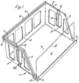
- Figure 1 shows a container, which may be used for transporting and displaying loaves of bread in vertical column stacking relationship, generally designated by the reference numeral 1 and comprising a rectangular base 2, upstanding from which are opposed side walls 3 and a rear wall 4.
- the container has an open front and top and the container is of an open framework structure.
- the front edges 5 of the side walls slope from near the front edge 6 of the base towards the back of the container, and meet upper side-wall edges 7 parallel to the base and on which the base of a similar container may be stacked.
- the side walls extend longitudinally of the container and, since the front edges slope, the upper edges are less extensive than the base.
- the upper edges of the side walls are integral with a lateral and rearward extension 8 defining a rebate together with an upper edge of the rear wall, for the reception of support means, in the form of a frame member shown at 9.
- the extension 8 provides stop means for the frame member, so that the member can be received in a first, inoperative position. With the frame member in this position the container can be used as a tray for transporting bread from place to place.
- the frame member comprises a U-shaped portion arranged to lie parallel to the base in the rebate in the inoperative position, and each leg of the U-shape is integral with a crank part extending perpendicularly to the base in this position.
- crank parts are pivotally connected at 9a to a respective opposed side wall of the container, substantially at the level of the base, so that the frame member is able to pivot about a transverse axis of the container.
- the frame member can be pivoted into a second position, to support a cantilevered end of an overlying similar container (shown at 9') in which the U-shaped portion of the frame member lies in a plane perpendicular to the base with the bridging part of the U-shaped portion ready to receive the end of the overlying container.
- the crank parts integral with the U-shaped portion abut stop means in the form of laterally outward extensions 10 and 11.
- the upper edges of the side walls 7 are provided with niches 12 to give access to the support member to move it to a supporting position.
- Figure 2 shows a container similar to that of Figure 1 which is provided with an integral lateral and rearward extension 8 defining a rebate along the upper edges of the opposed side walls for the frame member 9 to lie on (as in Figure 1), but the frame member 9 extends rearwardly beyond the container when located in the inoperative position.
- the frame member 9 differs from that shown in Figure 1 in that, when raised in the support position 9', the bridging part of the generally U-shaped portion is provided with crank support portions 13 and 14, extending longitudinally of the container, integral with a downwardly depending U-shaped portion 15.
- the portion 15 does not depend downwardly very far, since in the inoperative position shown, most of it must be accommodated within the rearward dimension of extension 8 of the back wall 4 of the container.
- the pivoting action of the frame member is the same as in Figure 1.
- the frame member is accommodated at least in part adjacent to the rear wall of the container to be substantially unobtrusive in the inoperative position.
- Figures 3 and 4 show another form of container provided with opposed side walls 3 each having upper edge portions 16 parallel to the base 2.
- the front edges 5 slope from the base to meet the upper edge portions 16, and side wall edge portions 17 slope from the top of the back wall 4 to meet the edge portions 16.
- the frame member is pivotally mounted at 20 on the upper edges of the side walls 16 towards the back of the container and is shown in the support position 9'.
- Crank parts 18 rest along the upper edges and are integral with a U-shaped frame portion projecting towards the front of the container and upwardly in a manner to support an overlying container.
- the frame member does not lie outwardly of the main container body. Again the member can be swung into an inoperative position where the U-shaped portion is located on the rear wall of the container.
- the frame member does not extend upwardly as high as the wall of the container in the support position as shown in the Figure, but the top of the back wall is recessed so that projections 19 can be hooked over the back wall of another container below it and the base of the overlying container may be supported in a plane parallel to the base of the underlying container.
- Figure 5 shows a fourth container in which support means is pivoted about an axis 20 at the top of the container, and when not in a supporting position lies inside the opposed side walls of the container.
- the support means comprises a pair of similar frame members (one of which is shown at 18) which are pivoted at 20 one on each side wall 3 so that when in the support position as shown they rest in a rebate 21 at the front of the container. In this latter position an overlying container is supported by longitudinally extending crank portions 18' of the two frame members.
- Each frame member is dog-legged to facilitate positioning of that member relative to the container. Pivotal movement of each frame member 18 from the support position to the inoperative position is in the direction indicated by the arrow.
- the container has a similar support facility to that shown in Figure 5 except that (a) the support means is in the form of a U-shaped frame member the legs of which are pivoted at 20 to the side walls 3 and which has a support position 9' (shown for the upper of the two nest stacked containers) and an inoperative position 9 (shown for the lower container), and (b) in the inoperative position of the support means the frame member 9 lies outside the side walls of the container.
- the scope of the invention extends to any member which may or may not be removable from the container and which may be moved to support the front end of another container in overlying relationship from an inoperative position, before or after the container is stacked on top.
- the member may be pivoted by any means or may be slidable into a support position.
- Two or more containers may be used to support a container in particular attitudes, and various stacking permutations may be possible.
Landscapes
- Engineering & Computer Science (AREA)
- Mechanical Engineering (AREA)
- Stackable Containers (AREA)
- Bakery Products And Manufacturing Methods Therefor (AREA)
- Table Devices Or Equipment (AREA)
- Thermally Insulated Containers For Foods (AREA)
- Containers And Packaging Bodies Having A Special Means To Remove Contents (AREA)
Abstract
Description
- This invention relates to a container having an open front for access to the contents carried on a base of the container, and particularly to a container which is intended to be stacked in overlying relationship with a similar container.
- Containers having an open front and an open top are well known, for example, for use in transporting loaves of bread into a supermarket. The containers may be stacked on top of one another in a vertical column to display the loaves and solthat access to the loaves carried on the base may be gained through the open front.
- Containers of this type have been provided with a rectangular base, two opposed and upstanding side walls, and an upstanding rear wall. The side walls may have upper edges less extensive than the base and sloping front edges to allow greater access to the bread, but if such is the case, the front end of an upper overlying container in a vertical column of such containers tends to overhang the top edges of the side walls of the immediately underlying container. In consequence, the front end of the base of the upper container is cantilevered with the disadvantage that an unstable configuration may be provided to the stack.
- An open fronted container is known from French Patent No. 1,387,232 which will stack as a vertical column with several similar containers by the base of each upper container in the stack being supported by a rear wall and a pivoted frame (when in a support position) of the immediately underlying container in the stack. With such an open fronted stacked container a considerable part length of the container extends forwardly of its support position, and in cantilevered manner from, the pivoted frame of the underlying container to the extent that the stacking configuration is unstable to pressure which may be applied to an upper container forwardly of its support position.
- It is an object of the present invention to provide means whereby the aforementioned disadvantages may be alleviated and to provide a container having cantilevered portions and which can be stacked with similar containers to provide a stable configuration.
- According to the present invention there is provided a container for stacking as a vertical column with a similar container which comprises a substantially flat base; wall means upstanding from the base, said wall means comprising opposed forwardly and rearwardly extending side wall parts and forming an open front and an open top; at least one upper edge for supporting the base of a similar container in vertically stacked overlying relationship, said upper edge being located on the wall means spaced from and rearwardly of the front of the base and said side wall parts forwardly of the upper edge being shaped to permit access to the container from the sides thereof adjacent to its open front, and a pivotally mounted frame member movable from a first, inoperative, position in which it is clear of said open front and open top and into a second position in which it abuts a stop and provides support to a said overlying container beneath the base of that container where the base of the overlying container is substantially parallel with the base of the underlying container characterised in that the frame member in its second position abuts the stop forwardly of and below the upper edge and said frame member in its second position provides a support part which extends upwardly from the stop and with respect to the base to form a support forwardly of the upper edge for supporting the base of an overlying container where that base projects forwardly in cantilevered manner from the support provided by the upper edge of the underlying container.
- The container has an open front, that is to say, the container may be provided with a front wall but at least part of the front wall is cut away for access into the interior of the container. Preferably the opposed wall parts have upper edges remote from the base on which the overlying container can be supported. The upper edges are conveniently less extensive than the base of the container.
- The container is preferably provided with a rectangular base, two opposed upstanding side walls and a rear wall.
- The container may alternatively have a curved upstanding wall which provides the opposed wall parts (instead of rear and opposed side walls) and which is sufficient to support one end of a similar overlying container in a cantilevered fashion.
- The frame member may be removable from the container completely to facilitate use of the container as a tray. The frame member may be pivotally mounted on the opposed wall parts or on the upper edges of the container and may swing inside or outside the opposed wall parts of the container.
- The opposed wall parts preferably extend longitudinally of the container and the frame member can be connected to the opposed wall parts to be pivotable about a generally transverse axis of the container.
- The frame member may be mounted on the container such that it is unobtrusive therefrom in the first, inoperative position; in other words, so that it does not interfere with use of the container as a tray and/or interfere with other containers placed in a side-by-side and/or back-to- back relationship. Where the container is provided with opposed side walls and a rear wall, the frame member may be accommodated at least in part adjacent to the rear wall of the container to be substantially unobtrusive therefrom.
- The frame member may comprise a generally U-shaped portion pivotable into a plane which extends substantially perpendicular to the base in the second, support position and which may receive the base of an overlying container. The legs of the U-shaped portion may be connected to the container by integral crank parts to enable the frame member to pivot about the transverse axis. The crank parts may extend longitudinally of the base when the frame member is in the second, support position and may receive the base of an overlying container. Alternatively the bridging part of the frame member may be provided with longitudinal and/or lateral crank portions to receive the overlying base.
- The U-shaped portion of the frame member may be inclined to the base in the supporting position and with the bridging part receiving an overlying container.
- The arrangement of the frame member is to provide maximum stability for an overlying container, and still be movable to an inoperative position which preferably does not interfere with the nest stacking of two containers nor interfere with the container if it is used as a tray. The frame member preferably does not extend beyond the lateral dimensions of the other parts of the container.
- The frame member may be positioned to pivot about an axis, for example above the base, and near the upper edges of the opposed wall parts. The axis may lie on the upper edges but may nevertheless be lower than the top of the container if the upper edges are suitably shaped; for example, the upper edges may comprise sloping portions.
- Stop means may be provided on the container to locate or engage the frame member in the supporting position on abutment therewith. The stop means may be in the form of laterally outward extensions against which the frame member rests in the second, support position. The extensions may be arranged substantially at the level of the base of the container and/or at the front of the container. The crank parts of the frame member may be located or engaged by the stop means, or alternatively the bridging part may abut the stop means which may be in the form of a rebate at the front of the container. The stop means may be located on the underside of the base to be engaged by or for abutment with the frame member of a similar underlying container when the frame member of that container is in the second, support position.
- Stop means may also be provided on the container for receiving the support means in the first, inoperative position. The stop means may be in the form of an integral extension defining a rebate around the top of the opposed wall parts of the container, or the upper edges of the wall parts or rear wall may provide the stop means.
- The container may be provided with rearward extensions or hooks to latch on to the rear wall of a similar container below it.
- Embodiments of the invention will now be described in accordance with the invention, by way of example only, with reference to the following drawings, in which:
- Figure 1 shows a perspective view of a first embodiment of a container provided with one form of support means;
- Figure 2 shows a perspective view of a second embodiment of a container provided with a second form of support means;
- Figure 3 shows a perspective view of a third embodiment of a container provided with a third form of support means;
- Figure 4 shows a side view of the embodiment shown in Figure 3;
- Figure 5 shows a side view of a fourth embodiment of container provided with a fourth form of support means; and
- Figure 6 is a perspective view of a fifth embodiment of container in which two similar containers are nest stacked.
- Figure 1 shows a container, which may be used for transporting and displaying loaves of bread in vertical column stacking relationship, generally designated by the reference numeral 1 and comprising a
rectangular base 2, upstanding from which areopposed side walls 3 and a rear wall 4. The container has an open front and top and the container is of an open framework structure. Thefront edges 5 of the side walls slope from near the front edge 6 of the base towards the back of the container, and meet upper side-wall edges 7 parallel to the base and on which the base of a similar container may be stacked. The side walls extend longitudinally of the container and, since the front edges slope, the upper edges are less extensive than the base. - The upper edges of the side walls are integral with a lateral and
rearward extension 8 defining a rebate together with an upper edge of the rear wall, for the reception of support means, in the form of a frame member shown at 9. Theextension 8 provides stop means for the frame member, so that the member can be received in a first, inoperative position. With the frame member in this position the container can be used as a tray for transporting bread from place to place. - As shown in Figure 1 the frame member comprises a U-shaped portion arranged to lie parallel to the base in the rebate in the inoperative position, and each leg of the U-shape is integral with a crank part extending perpendicularly to the base in this position.
- The free ends of the crank parts are pivotally connected at 9a to a respective opposed side wall of the container, substantially at the level of the base, so that the frame member is able to pivot about a transverse axis of the container. The frame member can be pivoted into a second position, to support a cantilevered end of an overlying similar container (shown at 9') in which the U-shaped portion of the frame member lies in a plane perpendicular to the base with the bridging part of the U-shaped portion ready to receive the end of the overlying container. In this position the crank parts integral with the U-shaped portion abut stop means in the form of laterally outward extensions 10 and 11. The upper edges of the side walls 7 are provided with
niches 12 to give access to the support member to move it to a supporting position. - Figure 2 shows a container similar to that of Figure 1 which is provided with an integral lateral and
rearward extension 8 defining a rebate along the upper edges of the opposed side walls for theframe member 9 to lie on (as in Figure 1), but theframe member 9 extends rearwardly beyond the container when located in the inoperative position. Theframe member 9 differs from that shown in Figure 1 in that, when raised in the support position 9', the bridging part of the generally U-shaped portion is provided withcrank support portions 13 and 14, extending longitudinally of the container, integral with a downwardly depending U-shapedportion 15. Theportion 15 does not depend downwardly very far, since in the inoperative position shown, most of it must be accommodated within the rearward dimension ofextension 8 of the back wall 4 of the container. The pivoting action of the frame member is the same as in Figure 1. Here, the frame member is accommodated at least in part adjacent to the rear wall of the container to be substantially unobtrusive in the inoperative position. - Figures 3 and 4 show another form of container provided with
opposed side walls 3 each havingupper edge portions 16 parallel to thebase 2. Thefront edges 5 slope from the base to meet theupper edge portions 16, and sidewall edge portions 17 slope from the top of the back wall 4 to meet theedge portions 16. The frame member is pivotally mounted at 20 on the upper edges of theside walls 16 towards the back of the container and is shown in the support position 9'. Crankparts 18 rest along the upper edges and are integral with a U-shaped frame portion projecting towards the front of the container and upwardly in a manner to support an overlying container. In this embodiment the frame member does not lie outwardly of the main container body. Again the member can be swung into an inoperative position where the U-shaped portion is located on the rear wall of the container. - The frame member does not extend upwardly as high as the wall of the container in the support position as shown in the Figure, but the top of the back wall is recessed so that
projections 19 can be hooked over the back wall of another container below it and the base of the overlying container may be supported in a plane parallel to the base of the underlying container. - Figure 5 shows a fourth container in which support means is pivoted about an
axis 20 at the top of the container, and when not in a supporting position lies inside the opposed side walls of the container. The support means comprises a pair of similar frame members (one of which is shown at 18) which are pivoted at 20 one on eachside wall 3 so that when in the support position as shown they rest in arebate 21 at the front of the container. In this latter position an overlying container is supported by longitudinally extending crank portions 18' of the two frame members. Each frame member is dog-legged to facilitate positioning of that member relative to the container. Pivotal movement of eachframe member 18 from the support position to the inoperative position is in the direction indicated by the arrow. - In the embodiment of Figure 6 the container has a similar support facility to that shown in Figure 5 except that (a) the support means is in the form of a U-shaped frame member the legs of which are pivoted at 20 to the
side walls 3 and which has a support position 9' (shown for the upper of the two nest stacked containers) and an inoperative position 9 (shown for the lower container), and (b) in the inoperative position of the support means theframe member 9 lies outside the side walls of the container. It will be apparent from Figure 6 that in its support position 9', the bridgingportion 22 of the frame member "U" shape abuts the upper surface of the front edge 6 while the legs of the "U" shape are cranked to provideportions 23 which extend longitudinally to receive and support the cantilevered base portion of a similar overlying container which may be stacked thereon. In itsinoperative position 9, the legs of the frame member "U" shape lie closely alongside therespective side walls 3 while the bridgingportion 22 is received and supported in the rebate provided by theextension 8 along the upper edge of the rear wall 4 - thereby leaving the open top of the container unobtruded to receive a similar container in nest stacking relationship as shown. - All of the embodiments described are such that the frame member is substantially unobtrusive in the first inoperative position.
- The scope of the invention extends to any member which may or may not be removable from the container and which may be moved to support the front end of another container in overlying relationship from an inoperative position, before or after the container is stacked on top. The member may be pivoted by any means or may be slidable into a support position. Two or more containers may be used to support a container in particular attitudes, and various stacking permutations may be possible.
Claims (17)
Priority Applications (1)
| Application Number | Priority Date | Filing Date | Title |
|---|---|---|---|
| AT80302961T ATE4494T1 (en) | 1979-10-30 | 1980-08-27 | STACKABLE CONTAINER. |
Applications Claiming Priority (2)
| Application Number | Priority Date | Filing Date | Title |
|---|---|---|---|
| GB7937534 | 1979-10-30 | ||
| GB7937534A GB2061227B (en) | 1979-10-30 | 1979-10-30 | Open-fronted container |
Publications (2)
| Publication Number | Publication Date |
|---|---|
| EP0028060A1 EP0028060A1 (en) | 1981-05-06 |
| EP0028060B1 true EP0028060B1 (en) | 1983-08-24 |
Family
ID=10508855
Family Applications (1)
| Application Number | Title | Priority Date | Filing Date |
|---|---|---|---|
| EP80302961A Expired EP0028060B1 (en) | 1979-10-30 | 1980-08-27 | A stackable container |
Country Status (8)
| Country | Link |
|---|---|
| US (1) | US4346805A (en) |
| EP (1) | EP0028060B1 (en) |
| AT (1) | ATE4494T1 (en) |
| AU (1) | AU531212B2 (en) |
| CA (1) | CA1126179A (en) |
| DE (1) | DE3064635D1 (en) |
| GB (1) | GB2061227B (en) |
| IE (1) | IE50166B1 (en) |
Families Citing this family (5)
| Publication number | Priority date | Publication date | Assignee | Title |
|---|---|---|---|---|
| NL8303781A (en) * | 1983-11-03 | 1985-06-03 | Curver Bv | NESTING AND STACKABLE CRATE. |
| GB2407557A (en) * | 2003-10-28 | 2005-05-04 | John Chapman | Portable open fronted receptacle for garden and industrial matter |
| US20070098542A1 (en) * | 2005-10-31 | 2007-05-03 | Foy Streeman | Rotational power system |
| US8025174B2 (en) * | 2008-05-30 | 2011-09-27 | Orbis Canada Limited | Residential recycling bin |
| US8950581B2 (en) * | 2010-11-30 | 2015-02-10 | Busch Systems International Inc. | Stackable container |
Family Cites Families (8)
| Publication number | Priority date | Publication date | Assignee | Title |
|---|---|---|---|---|
| US2528551A (en) * | 1944-10-30 | 1950-11-07 | Allen R Ross | Shipping box and crate |
| US2641383A (en) * | 1951-05-28 | 1953-06-09 | Charles Wm Doepke Mfg Company | Container with handle stacking means |
| US3018003A (en) * | 1960-07-08 | 1962-01-23 | Warren H Lockwood | Reversible and tiltably nestable containers |
| DE1201750B (en) * | 1963-09-04 | 1965-09-23 | Schaefer Kg Fritz | Transport box |
| FR1387232A (en) * | 1963-10-18 | 1965-01-29 | Cl Jacquemard Ets | Stackable and nestable storage bin |
| US3404804A (en) * | 1966-08-15 | 1968-10-08 | Lewis Co G B | Stackable-and nestable container |
| SE384993B (en) * | 1968-11-18 | 1976-05-31 | Bahr L Von | STACKABLE VARUBACK |
| GB1472173A (en) * | 1974-06-18 | 1977-05-04 | Lyons & Co Ltd J | Containers |
-
1979
- 1979-10-30 GB GB7937534A patent/GB2061227B/en not_active Expired
-
1980
- 1980-08-18 CA CA358,486A patent/CA1126179A/en not_active Expired
- 1980-08-27 DE DE8080302961T patent/DE3064635D1/en not_active Expired
- 1980-08-27 AT AT80302961T patent/ATE4494T1/en active
- 1980-08-27 EP EP80302961A patent/EP0028060B1/en not_active Expired
- 1980-09-18 US US06/188,579 patent/US4346805A/en not_active Expired - Lifetime
- 1980-10-15 IE IE2138/80A patent/IE50166B1/en unknown
- 1980-10-24 AU AU63665/80A patent/AU531212B2/en not_active Ceased
Also Published As
| Publication number | Publication date |
|---|---|
| US4346805A (en) | 1982-08-31 |
| IE802138L (en) | 1981-04-30 |
| ATE4494T1 (en) | 1983-09-15 |
| EP0028060A1 (en) | 1981-05-06 |
| AU531212B2 (en) | 1983-08-11 |
| GB2061227B (en) | 1983-08-10 |
| AU6366580A (en) | 1981-05-07 |
| CA1126179A (en) | 1982-06-22 |
| IE50166B1 (en) | 1986-02-19 |
| GB2061227A (en) | 1981-05-13 |
| DE3064635D1 (en) | 1983-09-29 |
Similar Documents
| Publication | Publication Date | Title |
|---|---|---|
| US4123128A (en) | Portable pie case | |
| KR0156949B1 (en) | Toolbox with tool pallet | |
| US3981511A (en) | Dispensing cart | |
| US4093071A (en) | Nesting and stacking container | |
| US4597616A (en) | Drawer-like container assembly | |
| US3999662A (en) | Merchandise display case | |
| US6260706B1 (en) | Multi-purpose tray | |
| US4372444A (en) | Stackable/nestable/dividable storage bin | |
| US5896992A (en) | Nestable bakery tray | |
| US4173289A (en) | Steel wire stackable upsettable-wall container | |
| US3082879A (en) | Receptacle | |
| US20060096883A1 (en) | Multi-level stacking container | |
| US4859010A (en) | Refrigerator door tray assembly | |
| US2950825A (en) | Stacking crates or receptacles | |
| US7484621B2 (en) | Tray | |
| EP0697341A1 (en) | Container having means for stacking at three different levels | |
| US4346805A (en) | Container | |
| US3581932A (en) | Nest and stack containers | |
| US3002795A (en) | Counter display cases | |
| US4217985A (en) | Display device for storing and displaying cards | |
| GB2374859A (en) | Open topped container capable of nesting and stacking | |
| US4830189A (en) | Container | |
| US5104114A (en) | Stacking device with container having movable bottom | |
| US4236775A (en) | Storage holder for firewood and the like | |
| US3896962A (en) | Portable file box with file suspension and carrying means |
Legal Events
| Date | Code | Title | Description |
|---|---|---|---|
| PUAI | Public reference made under article 153(3) epc to a published international application that has entered the european phase |
Free format text: ORIGINAL CODE: 0009012 |
|
| AK | Designated contracting states |
Designated state(s): AT BE DE FR IT LU NL SE |
|
| 17P | Request for examination filed |
Effective date: 19810316 |
|
| GRAA | (expected) grant |
Free format text: ORIGINAL CODE: 0009210 |
|
| AK | Designated contracting states |
Designated state(s): AT BE DE FR IT LU NL SE |
|
| PG25 | Lapsed in a contracting state [announced via postgrant information from national office to epo] |
Ref country code: SE Effective date: 19830824 Ref country code: IT Free format text: LAPSE BECAUSE OF FAILURE TO SUBMIT A TRANSLATION OF THE DESCRIPTION OR TO PAY THE FEE WITHIN THE PRESCRIBED TIME-LIMIT;WARNING: LAPSES OF ITALIAN PATENTS WITH EFFECTIVE DATE BEFORE 2007 MAY HAVE OCCURRED AT ANY TIME BEFORE 2007. THE CORRECT EFFECTIVE DATE MAY BE DIFFERENT FROM THE ONE RECORDED. Effective date: 19830824 Ref country code: BE Effective date: 19830824 |
|
| REF | Corresponds to: |
Ref document number: 4494 Country of ref document: AT Date of ref document: 19830915 Kind code of ref document: T |
|
| PG25 | Lapsed in a contracting state [announced via postgrant information from national office to epo] |
Ref country code: LU Free format text: LAPSE BECAUSE OF NON-PAYMENT OF DUE FEES Effective date: 19830831 |
|
| PG25 | Lapsed in a contracting state [announced via postgrant information from national office to epo] |
Ref country code: AT Effective date: 19830901 |
|
| REF | Corresponds to: |
Ref document number: 3064635 Country of ref document: DE Date of ref document: 19830929 |
|
| ET | Fr: translation filed | ||
| RAP2 | Party data changed (patent owner data changed or rights of a patent transferred) |
Owner name: LIN PAC MOULDINGS LIMITED |
|
| PLBE | No opposition filed within time limit |
Free format text: ORIGINAL CODE: 0009261 |
|
| STAA | Information on the status of an ep patent application or granted ep patent |
Free format text: STATUS: NO OPPOSITION FILED WITHIN TIME LIMIT |
|
| 26N | No opposition filed | ||
| PGFP | Annual fee paid to national office [announced via postgrant information from national office to epo] |
Ref country code: FR Payment date: 19910808 Year of fee payment: 12 |
|
| PGFP | Annual fee paid to national office [announced via postgrant information from national office to epo] |
Ref country code: NL Payment date: 19910831 Year of fee payment: 12 |
|
| PGFP | Annual fee paid to national office [announced via postgrant information from national office to epo] |
Ref country code: DE Payment date: 19910930 Year of fee payment: 12 |
|
| PG25 | Lapsed in a contracting state [announced via postgrant information from national office to epo] |
Ref country code: NL Effective date: 19930301 |
|
| NLV4 | Nl: lapsed or anulled due to non-payment of the annual fee | ||
| PG25 | Lapsed in a contracting state [announced via postgrant information from national office to epo] |
Ref country code: FR Effective date: 19930430 |
|
| PG25 | Lapsed in a contracting state [announced via postgrant information from national office to epo] |
Ref country code: DE Effective date: 19930501 |
|
| REG | Reference to a national code |
Ref country code: FR Ref legal event code: ST |