EP0027432B2 - Electronic data memorising circuit in a domestic electrical appliance - Google Patents
Electronic data memorising circuit in a domestic electrical appliance Download PDFInfo
- Publication number
- EP0027432B2 EP0027432B2 EP80830076A EP80830076A EP0027432B2 EP 0027432 B2 EP0027432 B2 EP 0027432B2 EP 80830076 A EP80830076 A EP 80830076A EP 80830076 A EP80830076 A EP 80830076A EP 0027432 B2 EP0027432 B2 EP 0027432B2
- Authority
- EP
- European Patent Office
- Prior art keywords
- memory
- programme
- auxiliary
- data
- circuit
- Prior art date
- Legal status (The legal status is an assumption and is not a legal conclusion. Google has not performed a legal analysis and makes no representation as to the accuracy of the status listed.)
- Expired
Links
Images
Classifications
-
- G—PHYSICS
- G06—COMPUTING OR CALCULATING; COUNTING
- G06F—ELECTRIC DIGITAL DATA PROCESSING
- G06F1/00—Details not covered by groups G06F3/00 - G06F13/00 and G06F21/00
- G06F1/26—Power supply means, e.g. regulation thereof
- G06F1/30—Means for acting in the event of power-supply failure or interruption, e.g. power-supply fluctuations
-
- G—PHYSICS
- G05—CONTROLLING; REGULATING
- G05B—CONTROL OR REGULATING SYSTEMS IN GENERAL; FUNCTIONAL ELEMENTS OF SUCH SYSTEMS; MONITORING OR TESTING ARRANGEMENTS FOR SUCH SYSTEMS OR ELEMENTS
- G05B19/00—Program-control systems
- G05B19/02—Program-control systems electric
- G05B19/04—Program control other than numerical control, i.e. in sequence controllers or logic controllers
- G05B19/042—Program control other than numerical control, i.e. in sequence controllers or logic controllers using digital processors
- G05B19/0428—Safety, monitoring
-
- G—PHYSICS
- G05—CONTROLLING; REGULATING
- G05B—CONTROL OR REGULATING SYSTEMS IN GENERAL; FUNCTIONAL ELEMENTS OF SUCH SYSTEMS; MONITORING OR TESTING ARRANGEMENTS FOR SUCH SYSTEMS OR ELEMENTS
- G05B2219/00—Program-control systems
- G05B2219/20—Pc systems
- G05B2219/23—Pc programming
- G05B2219/23215—Check data validity in ram, keep correct validity, compare rom ram
-
- G—PHYSICS
- G05—CONTROLLING; REGULATING
- G05B—CONTROL OR REGULATING SYSTEMS IN GENERAL; FUNCTIONAL ELEMENTS OF SUCH SYSTEMS; MONITORING OR TESTING ARRANGEMENTS FOR SUCH SYSTEMS OR ELEMENTS
- G05B2219/00—Program-control systems
- G05B2219/20—Pc systems
- G05B2219/24—Pc safety
- G05B2219/24139—Recovery from power loss, failure
-
- G—PHYSICS
- G05—CONTROLLING; REGULATING
- G05B—CONTROL OR REGULATING SYSTEMS IN GENERAL; FUNCTIONAL ELEMENTS OF SUCH SYSTEMS; MONITORING OR TESTING ARRANGEMENTS FOR SUCH SYSTEMS OR ELEMENTS
- G05B2219/00—Program-control systems
- G05B2219/20—Pc systems
- G05B2219/25—Pc structure of the system
- G05B2219/25381—Restart program at predetermined position, crash recovery after power loss
Definitions
- the present invention relates to a circuit as set forth in the first portion of appended Claim 1.
- GB-A 1 529 691 Another kind of timer for a washing machine is disclosed in GB-A 1 529 691.
- This known device includes a partly electronic, partly electromechanical logic circuit capable of discriminating, by means of a switch associated with the mains switch of the machine, whether the machine has been siwtched off intentionally or there has been a power failure.
- the said logic circuit includes bistable electronic memory circuits having a battery back-up supply and an electromechanical relay which senses whether the current supply has been deliberately interrupted and, if so, causes the memory circuits to be reset by interrupting the back-up supply.
- the known control and timing devices which include mechanical or electromechanical components are now being replaced by wholly electronic devices.
- the wholly eiectronic devices now being used usually comprise a processing unit (microprocessor), a fixed operating programme memory (ROM) and a read-write memory (RAM) for memorising information data relative to the programme being performed.
- Eiectronic devices of this kind have a greater processing capacity than their electromechanical counterparts which means they can perform more sophisticated programmes, be controlled automatically, indicate various operating defects and so on.
- the memory must be capable of preserving data in the event of an accidental power cut on the mains.
- Microprocessors are usually fitted with a special circuit, known as an "On reset" circuit, for restarting them when supply is restored after a power cut.
- the on/off switch When power is restored, a check can then be made to ascertain whether the on/off switch is closed or open and whether the programme is to be continued or not.
- the on/off switch must have two sections: one of which closes immediately and supplies the processing unit and the other of which closes after a delay and whose condition is checked by the processing unit which, if it finds it open, starts the machine up again from the beginning.
- the aim of the present invention is to provide a simple, reliable wholly electronic circuit with the above performance.
- the present invention relates to as circuit for memorising in digital form in an electronic memory information relating to a programme operating in a domestic appliance, in particular, a clothes washing machine, as set forth in the first part of Claim 1, having the features recited in the characterizing portion of Claim 1.
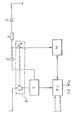
- the attached drawing shows a block diagram of a memory circuit according to the present invention.
- the letter L represents the power supply line (household mains), T the on/off switch on the machine (e.g. washing machine), having two sections T 1 and T 2 , and S a power unit for supplying processing unit PU and a number of other possible circuits not shown (electromechanical actuators, etc.).
- Unit S is also connected via diode D and resistor R to battery B.
- the voltage of battery B is lower than that supplied by unit S.
- the battery voltage may be 2.4 V (2 rechargeable nickelcadmium cells) whereas the voltage supplied by S may be 5 V.
- An electronic memory M e.g. Intel 5101 L-3 256x4 bit RAM
- T 2 of switch T mechanically connected to the first from the intersection of diode D and resistor R.
- the processing unit PU e.g. Fairchild F 3870 microprocessor
- the processing unit PU is connected to memory M by a number of lines (4 two-way lines for data, 5 for addresses 2 for control) and also to a number of signal inputs (two are exemplified on the diagram, 1 1 and ⁇ 2 ) for example, from a keyboard and sensor devices (thermostats, pressure switches, etc.) and a number of signal outputs (two are exemplified on the diagram, 0 1 and 0 2 ), connected, for example, to display (LED) and actuator (triac) devices for controlling the motor, heating resistor, electrovalves, etc.
- LED display
- actuator triac
- Processing unit PU contains a 2048-byte ROM containing the machine's operating programme. This may comprise a sequence of control and actuating operations for enabling the machine to perform one or more (e.g. wash) programmes according to the data received initially (e.g. when the machine was turned on) from the operator (e.g. from the keyboard).
- Each programme will comprise a number of successive stages (e.g. soak, prewash, heat, wash, rinses, spinning).
- the invention is designed so that, a number of times during the programme (e.g. at the start of each of the abovementioned stages), the PU provides for memorising in M the data required for taking up the programme following a power cut.
- Such data may be represented, for example, by 8 bytes, to indicate:
- the PU When supply is restored after a power cut, the PU performs the automatic "ON RESET" cycle which starts the programme counter from a preset point (0000 in the case of F 3870).
- the invention is designed so that a memory reading (data call up) routine is situated at this point for checking the data is correct. If it is found to be correct, the PU restores the required data in the appropriate registers and sets the programme counter so as to take up the programme more or less from where it was left off. If the data is found to be incorrect, however, the PU waits for further instructions from the operator (from the keyboard) by returning to the start of the programme.
Landscapes
- Engineering & Computer Science (AREA)
- Physics & Mathematics (AREA)
- General Physics & Mathematics (AREA)
- Theoretical Computer Science (AREA)
- General Engineering & Computer Science (AREA)
- Automation & Control Theory (AREA)
- Control Of Washing Machine And Dryer (AREA)
- Techniques For Improving Reliability Of Storages (AREA)
Description
- The present invention relates to a circuit as set forth in the first portion of appended Claim 1.
- Up to now, so-called automatic household appliances (clothes- and dish-washing machines, ovens, etc.) have been fitted mainly with mechanical or electromechanical timers.
- Another kind of timer for a washing machine is disclosed in GB-A 1 529 691. This known device includes a partly electronic, partly electromechanical logic circuit capable of discriminating, by means of a switch associated with the mains switch of the machine, whether the machine has been siwtched off intentionally or there has been a power failure. The said logic circuit includes bistable electronic memory circuits having a battery back-up supply and an electromechanical relay which senses whether the current supply has been deliberately interrupted and, if so, causes the memory circuits to be reset by interrupting the back-up supply.
- The known control and timing devices which include mechanical or electromechanical components are now being replaced by wholly electronic devices. The wholly eiectronic devices now being used usually comprise a processing unit (microprocessor), a fixed operating programme memory (ROM) and a read-write memory (RAM) for memorising information data relative to the programme being performed.
- Eiectronic devices of this kind have a greater processing capacity than their electromechanical counterparts which means they can perform more sophisticated programmes, be controlled automatically, indicate various operating defects and so on. One problem exists, however, as regards data memorization. The memory must be capable of preserving data in the event of an accidental power cut on the mains. Two solutions are available:
- - volatile memory with an auxiliary supply battery,
- - non-volatile memory.
- In both cases, it is desirable:
- - for the programme to be taken up more or less from where it was left off in the event of an accidental power cut;
- - for the machine to "forget" the programme it was performing and start again from the beginning if it is turned off manually by the operator before the programme has been finished. This enables the operator to reselect the programme if a wrong one is started.
- For this purpose, it is common practice to fit the on/off switch with a second section and to interlock this second section with continuation of the interrupted programme or resetting to the starting point of the programme.
- Electronic processing devices (microprocessors) are usually fitted with a special circuit, known as an "On reset" circuit, for restarting them when supply is restored after a power cut.
- When power is restored, a check can then be made to ascertain whether the on/off switch is closed or open and whether the programme is to be continued or not. To ensure smooth operation of this system, the on/off switch must have two sections: one of which closes immediately and supplies the processing unit and the other of which closes after a delay and whose condition is checked by the processing unit which, if it finds it open, starts the machine up again from the beginning.
- This system is critical and demands a special switch. The aim of the present invention is to provide a simple, reliable wholly electronic circuit with the above performance.
- With this aim in view, the present invention relates to as circuit for memorising in digital form in an electronic memory information relating to a programme operating in a domestic appliance, in particular, a clothes washing machine, as set forth in the first part of Claim 1, having the features recited in the characterizing portion of Claim 1.
- The invention will now be described in detail with reference to the attached drawing provided by way of a non-limiting example.
- The attached drawing shows a block diagram of a memory circuit according to the present invention.
- The letter L represents the power supply line (household mains), T the on/off switch on the machine (e.g. washing machine), having two sections T1 and T2, and S a power unit for supplying processing unit PU and a number of other possible circuits not shown (electromechanical actuators, etc.).
- Unit S is also connected via diode D and resistor R to battery B. The voltage of battery B is lower than that supplied by unit S. For example, the battery voltage may be 2.4 V (2 rechargeable nickelcadmium cells) whereas the voltage supplied by S may be 5 V. An electronic memory M (e.g. Intel 5101 L-3 256x4 bit RAM) is supplied via the second section T2 of switch T, mechanically connected to the first from the intersection of diode D and resistor R.
- The processing unit PU (e.g. Fairchild F 3870 microprocessor) is connected to memory M by a number of lines (4 two-way lines for data, 5 for addresses 2 for control) and also to a number of signal inputs (two are exemplified on the diagram, 11 and <2) for example, from a keyboard and sensor devices (thermostats, pressure switches, etc.) and a number of signal outputs (two are exemplified on the diagram, 01 and 02), connected, for example, to display (LED) and actuator (triac) devices for controlling the motor, heating resistor, electrovalves, etc.
- None of these devices is shown on the diagram in that they are known types not pertinent to the invention. The circuit described operates as follows.
- Processing unit PU contains a 2048-byte ROM containing the machine's operating programme. This may comprise a sequence of control and actuating operations for enabling the machine to perform one or more (e.g. wash) programmes according to the data received initially (e.g. when the machine was turned on) from the operator (e.g. from the keyboard).
- Each programme will comprise a number of successive stages (e.g. soak, prewash, heat, wash, rinses, spinning).
- It is not necessary here to describe these operations in detail or how they are controlled by the PU.
- The invention is designed so that, a number of times during the programme (e.g. at the start of each of the abovementioned stages), the PU provides for memorising in M the data required for taking up the programme following a power cut. Such data may be represented, for example, by 8 bytes, to indicate:
- - the number of the programme being performed,
- - the programme stage being performed,
- - input-output status,
- - any special options selected by the operator at the beginning (economy cycle, slow spin, etc.). Besides this data, the PU also memorises a set of control data (e.g. the ones complement to one of the 8 data bytes) for checking the called up data is correct.
- In the example given, a total of 16 bytes have to be memorised occupying 32 cells of the 256x4. When supply is restored after a power cut, the PU performs the automatic "ON RESET" cycle which starts the programme counter from a preset point (0000 in the case of F 3870). The invention is designed so that a memory reading (data call up) routine is situated at this point for checking the data is correct. If it is found to be correct, the PU restores the required data in the appropriate registers and sets the programme counter so as to take up the programme more or less from where it was left off. If the data is found to be incorrect, however, the PU waits for further instructions from the operator (from the keyboard) by returning to the start of the programme. In view of the circuit arrangement, it will be clear that, if power failure is due to an accidental power cut on the mains, switch T will remain closed, memory M will be supplied by battery B and the data read will be correct. If, on the other hand, the power cut is due to the operator turning the machine off, memory M will be left unsupplied during the interruption, the data will be lost so that the random data read will be incorrect.
- Variations can, of course, be made to the circuit described. For example, instead of using an F 3870 microprocessor and a separate memory, an F 3876 can be used which incorporates a battery- suppliable 128x8 RAM. Or, instead of a volatile RAM from which supply is cut off by the on/off switch, a clearable nonvolatile RAM can be used with the memory clearing bit controlled by the second section of switch T. The advantages of the circuit in terms of simplicity and reliability will be clear from the description given. It should be pointed out that the fact that the 2 sections of switch T open and/or close before or after one another has no effect on operation and that correct data reading is highly realiable: in the example given, the probability of the bits being correctly distributed by chance is 1/264.
Claims (5)
Applications Claiming Priority (2)
| Application Number | Priority Date | Filing Date | Title |
|---|---|---|---|
| IT68915/79A IT1118947B (en) | 1979-10-04 | 1979-10-04 | ELECTRONIC CIRCUIT FOR STORING DATA IN A HOME APPLIANCE APPARATUS |
| IT6891579 | 1979-10-04 |
Publications (4)
| Publication Number | Publication Date |
|---|---|
| EP0027432A2 EP0027432A2 (en) | 1981-04-22 |
| EP0027432A3 EP0027432A3 (en) | 1981-05-06 |
| EP0027432B1 EP0027432B1 (en) | 1984-04-18 |
| EP0027432B2 true EP0027432B2 (en) | 1988-08-24 |
Family
ID=11310907
Family Applications (1)
| Application Number | Title | Priority Date | Filing Date |
|---|---|---|---|
| EP80830076A Expired EP0027432B2 (en) | 1979-10-04 | 1980-10-06 | Electronic data memorising circuit in a domestic electrical appliance |
Country Status (3)
| Country | Link |
|---|---|
| EP (1) | EP0027432B2 (en) |
| DE (1) | DE3067559D1 (en) |
| IT (1) | IT1118947B (en) |
Families Citing this family (19)
| Publication number | Priority date | Publication date | Assignee | Title |
|---|---|---|---|---|
| FR2506038A1 (en) * | 1981-05-12 | 1982-11-19 | Carpano & Pons | Programmable micro-calculator for controlling domestic equipment - contains switching circuit to connect micro-calculator back up power supply when mains supply trips out |
| JPS58168119A (en) * | 1982-03-30 | 1983-10-04 | Nec Corp | System for discriminating momentary interruption of power supply |
| JPS58193027A (en) * | 1982-05-04 | 1983-11-10 | Matsushita Electric Ind Co Ltd | Heater |
| JPS5917816A (en) * | 1982-07-16 | 1984-01-30 | 株式会社東芝 | Operation protecting device for electric equipment |
| DE3301603C1 (en) * | 1983-01-19 | 1984-07-05 | Diehl GmbH & Co, 8500 Nürnberg | Control circuit for a microcomputer |
| JPS59163649A (en) * | 1983-02-28 | 1984-09-14 | デイ−ア・アンド・カンパニ− | Detection of non-volatile memory fault |
| GB2145254A (en) * | 1983-08-17 | 1985-03-20 | Philips Electronic Associated | Domestic electrical appliance |
| GB2145253A (en) * | 1983-08-17 | 1985-03-20 | Philips Electronic Associated | Method of controlling a domestic appliance |
| DE3343227A1 (en) * | 1983-11-30 | 1985-06-05 | Robert Bosch Gmbh, 7000 Stuttgart | METHOD FOR MONITORING ELECTRONIC COMPUTERS, IN PARTICULAR MICROPROCESSORS |
| JPS60160333A (en) * | 1984-01-30 | 1985-08-21 | ソニー株式会社 | Electronic device |
| FR2571870B1 (en) * | 1984-10-15 | 1987-02-20 | Sagem | MICROPROCESSOR MEMORY BACKUP DEVICE. |
| US4862493A (en) * | 1987-12-28 | 1989-08-29 | General Electric Company | Electronic remote data recorder for electric energy metering |
| FR2646535B1 (en) * | 1989-04-28 | 1991-08-23 | Somfy | ELECTRONIC DEVICE FOR CONTROLLING AT LEAST ONE ELECTRIC RECEIVER |
| DE4425383A1 (en) * | 1994-07-19 | 1996-01-25 | Ako Werke Gmbh & Co | Circuit arrangement for a household machine |
| WO2000045520A1 (en) * | 1999-01-29 | 2000-08-03 | Koninklijke Philips Electronics N.V. | Apparatus which is electronically switched on and off |
| FR2797788B1 (en) | 1999-08-30 | 2001-11-23 | Sames Sa | PRODUCT CHANGE METHOD AND STATION IN A COATING PRODUCT SPRAYING SYSTEM |
| DE19943124A1 (en) * | 1999-09-09 | 2001-03-15 | Bsh Bosch Siemens Hausgeraete | Device for detecting a power failure in a program-controlled household appliance |
| DE19954258A1 (en) * | 1999-11-11 | 2001-05-17 | Truetzschler Gmbh & Co Kg | Device for the electronic control of spinning machines, in particular spinning preparation machines |
| EP2798722A2 (en) * | 2011-12-26 | 2014-11-05 | Arçelik Anonim Sirketi | A household appliance protected from mains over voltage |
Family Cites Families (3)
| Publication number | Priority date | Publication date | Assignee | Title |
|---|---|---|---|---|
| US4054911A (en) * | 1976-06-03 | 1977-10-18 | Idr, Inc. | Information retrieval system for providing downstream loading of remote data and processing control thereof |
| DE2716240A1 (en) * | 1977-04-13 | 1978-10-26 | Kieninger & Obergfell | Electrical program control unit for household machines - has electronic program instruction store and interchangeable mechanical program unit |
| JPS5494850A (en) * | 1978-01-11 | 1979-07-26 | Nissan Motor | Arithmetic processor |
-
1979
- 1979-10-04 IT IT68915/79A patent/IT1118947B/en active
-
1980
- 1980-10-06 DE DE8080830076T patent/DE3067559D1/en not_active Expired
- 1980-10-06 EP EP80830076A patent/EP0027432B2/en not_active Expired
Also Published As
| Publication number | Publication date |
|---|---|
| IT7968915A0 (en) | 1979-10-04 |
| EP0027432A3 (en) | 1981-05-06 |
| EP0027432A2 (en) | 1981-04-22 |
| IT1118947B (en) | 1986-03-03 |
| DE3067559D1 (en) | 1984-05-24 |
| EP0027432B1 (en) | 1984-04-18 |
Similar Documents
| Publication | Publication Date | Title |
|---|---|---|
| EP0027432B1 (en) | Electronic data memorising circuit in a domestic electrical appliance | |
| US4241400A (en) | Microprocessor based control circuit for washing appliances | |
| CA1169567A (en) | Method of controlling an apparatus, which is operated by a solid-state processor and powered by an electric mains, in case of a power failure and apparatus employing said method | |
| US4418398A (en) | Manual reset control circuit for microprocessor controlled washing appliance | |
| US4245310A (en) | Microprocessor based control circuit for washing appliances with overfill protection | |
| US4245309A (en) | Microprocessor based control circuit for washing appliances with diagnostic system | |
| US3464437A (en) | Overflow protection device | |
| US6684111B2 (en) | Apparatus for power failure identification in a programmable household appliance and method for identifying power failure | |
| US4449384A (en) | Washing appliance control circuitry | |
| EP0775463A2 (en) | Dishwasher and control therefor | |
| GB2039677A (en) | Apparatus comprising a digital processor and function test means | |
| JP2839527B2 (en) | How to operate an electronically controlled washing machine | |
| EP0134610B1 (en) | Domestic electrical appliance | |
| US4631658A (en) | Method of and apparatus for controlling a domestic appliance | |
| EP0924331A2 (en) | Safety circuit for a heating circuit of a washing machine, dishwasher or drier | |
| US4334143A (en) | Heater protection arrangement for a washing appliance | |
| US3861413A (en) | Indicating device for a dishwasher | |
| US4305122A (en) | Method and system for controlling a dishwashing apparatus | |
| US4213313A (en) | Relay control circuit for washing appliance | |
| EP0293223A1 (en) | Improvements relating to domestic appliances | |
| RU2497989C2 (en) | Electronic safety system for household appliance with door | |
| WO2001009693A1 (en) | Power up communication interface system | |
| JP3629877B2 (en) | Washing machine | |
| EP0381022A1 (en) | A door locking means for a washing and/or drying machine for laundry | |
| JP2002355212A (en) | Power failure recovery type dishwasher / dryer recovery type fully automatic washer / dryer and power failure recovery type electrical equipment |
Legal Events
| Date | Code | Title | Description |
|---|---|---|---|
| PUAI | Public reference made under article 153(3) epc to a published international application that has entered the european phase |
Free format text: ORIGINAL CODE: 0009012 |
|
| PUAL | Search report despatched |
Free format text: ORIGINAL CODE: 0009013 |
|
| AK | Designated contracting states |
Designated state(s): BE DE FR GB NL |
|
| AK | Designated contracting states |
Designated state(s): BE DE FR GB NL |
|
| 17P | Request for examination filed |
Effective date: 19810813 |
|
| GRAA | (expected) grant |
Free format text: ORIGINAL CODE: 0009210 |
|
| AK | Designated contracting states |
Designated state(s): BE DE FR GB NL |
|
| REF | Corresponds to: |
Ref document number: 3067559 Country of ref document: DE Date of ref document: 19840524 |
|
| ET | Fr: translation filed | ||
| PLBI | Opposition filed |
Free format text: ORIGINAL CODE: 0009260 |
|
| 26 | Opposition filed |
Opponent name: MIELE & CIE. GMBH & CO Effective date: 19850117 |
|
| NLR1 | Nl: opposition has been filed with the epo |
Opponent name: MIELE & CIE. GMBH & CO. |
|
| PUAH | Patent maintained in amended form |
Free format text: ORIGINAL CODE: 0009272 |
|
| STAA | Information on the status of an ep patent application or granted ep patent |
Free format text: STATUS: PATENT MAINTAINED AS AMENDED |
|
| 27A | Patent maintained in amended form |
Effective date: 19880824 |
|
| AK | Designated contracting states |
Kind code of ref document: B2 Designated state(s): BE DE FR GB NL |
|
| NLR2 | Nl: decision of opposition | ||
| ET3 | Fr: translation filed ** decision concerning opposition | ||
| NLR3 | Nl: receipt of modified translations in the netherlands language after an opposition procedure | ||
| PGFP | Annual fee paid to national office [announced via postgrant information from national office to epo] |
Ref country code: NL Payment date: 19991029 Year of fee payment: 20 Ref country code: FR Payment date: 19991029 Year of fee payment: 20 Ref country code: BE Payment date: 19991029 Year of fee payment: 20 |
|
| PGFP | Annual fee paid to national office [announced via postgrant information from national office to epo] |
Ref country code: GB Payment date: 19991102 Year of fee payment: 20 |
|
| PGFP | Annual fee paid to national office [announced via postgrant information from national office to epo] |
Ref country code: DE Payment date: 19991116 Year of fee payment: 20 |
|
| BE20 | Be: patent expired |
Free format text: 20001006 *INDESIT INDUSTRIA ELETTRODOMESTICI ITALIANA S.P.A. |
|
| PG25 | Lapsed in a contracting state [announced via postgrant information from national office to epo] |
Ref country code: GB Free format text: LAPSE BECAUSE OF EXPIRATION OF PROTECTION Effective date: 20001005 |
|
| PG25 | Lapsed in a contracting state [announced via postgrant information from national office to epo] |
Ref country code: NL Free format text: LAPSE BECAUSE OF EXPIRATION OF PROTECTION Effective date: 20001006 |
|
| REG | Reference to a national code |
Ref country code: GB Ref legal event code: PE20 Effective date: 20001005 |
|
| NLV7 | Nl: ceased due to reaching the maximum lifetime of a patent |
Effective date: 20001006 |