EP0026781B1 - Method for coating a workpiece - Google Patents
Method for coating a workpiece Download PDFInfo
- Publication number
- EP0026781B1 EP0026781B1 EP80900751A EP80900751A EP0026781B1 EP 0026781 B1 EP0026781 B1 EP 0026781B1 EP 80900751 A EP80900751 A EP 80900751A EP 80900751 A EP80900751 A EP 80900751A EP 0026781 B1 EP0026781 B1 EP 0026781B1
- Authority
- EP
- European Patent Office
- Prior art keywords
- water
- volatile organic
- organic compound
- spraybooth
- accordance
- Prior art date
- Legal status (The legal status is an assumption and is not a legal conclusion. Google has not performed a legal analysis and makes no representation as to the accuracy of the status listed.)
- Expired
Links
- 238000000034 method Methods 0.000 title claims abstract description 28
- 238000000576 coating method Methods 0.000 title claims abstract description 13
- 239000011248 coating agent Substances 0.000 title claims abstract description 9
- XLYOFNOQVPJJNP-UHFFFAOYSA-N water Substances O XLYOFNOQVPJJNP-UHFFFAOYSA-N 0.000 claims abstract description 133
- 238000005201 scrubbing Methods 0.000 claims abstract description 51
- 239000012855 volatile organic compound Substances 0.000 claims abstract description 47
- 239000008199 coating composition Substances 0.000 claims abstract description 33
- 230000008569 process Effects 0.000 claims abstract description 22
- 238000005507 spraying Methods 0.000 claims abstract description 10
- SVONRAPFKPVNKG-UHFFFAOYSA-N 2-ethoxyethyl acetate Chemical compound CCOCCOC(C)=O SVONRAPFKPVNKG-UHFFFAOYSA-N 0.000 claims description 24
- 239000007789 gas Substances 0.000 claims description 18
- RTZKZFJDLAIYFH-UHFFFAOYSA-N Diethyl ether Chemical compound CCOCC RTZKZFJDLAIYFH-UHFFFAOYSA-N 0.000 claims description 9
- 150000002148 esters Chemical class 0.000 claims description 8
- 238000009835 boiling Methods 0.000 claims description 7
- OAYXUHPQHDHDDZ-UHFFFAOYSA-N 2-(2-butoxyethoxy)ethanol Chemical compound CCCCOCCOCCO OAYXUHPQHDHDDZ-UHFFFAOYSA-N 0.000 claims description 4
- LFQSCWFLJHTTHZ-UHFFFAOYSA-N Ethanol Chemical compound CCO LFQSCWFLJHTTHZ-UHFFFAOYSA-N 0.000 claims description 2
- 239000003039 volatile agent Substances 0.000 abstract 1
- 210000003298 dental enamel Anatomy 0.000 description 52
- 150000001875 compounds Chemical class 0.000 description 45
- 239000002904 solvent Substances 0.000 description 38
- 239000003570 air Substances 0.000 description 36
- 239000003973 paint Substances 0.000 description 22
- 238000005070 sampling Methods 0.000 description 19
- 239000000523 sample Substances 0.000 description 18
- 239000007921 spray Substances 0.000 description 16
- 239000010802 sludge Substances 0.000 description 14
- 238000004817 gas chromatography Methods 0.000 description 12
- 239000000463 material Substances 0.000 description 12
- 238000005259 measurement Methods 0.000 description 12
- 238000004458 analytical method Methods 0.000 description 11
- 238000004519 manufacturing process Methods 0.000 description 11
- 239000000203 mixture Substances 0.000 description 11
- 239000007787 solid Substances 0.000 description 10
- ZNQVEEAIQZEUHB-UHFFFAOYSA-N 2-ethoxyethanol Chemical compound CCOCCO ZNQVEEAIQZEUHB-UHFFFAOYSA-N 0.000 description 7
- 239000004215 Carbon black (E152) Substances 0.000 description 7
- 229930195733 hydrocarbon Natural products 0.000 description 7
- 150000002430 hydrocarbons Chemical class 0.000 description 7
- ATUOYWHBWRKTHZ-UHFFFAOYSA-N Propane Chemical compound CCC ATUOYWHBWRKTHZ-UHFFFAOYSA-N 0.000 description 5
- 238000007792 addition Methods 0.000 description 5
- 230000009467 reduction Effects 0.000 description 5
- XLLIQLLCWZCATF-UHFFFAOYSA-N 2-methoxyethyl acetate Chemical compound COCCOC(C)=O XLLIQLLCWZCATF-UHFFFAOYSA-N 0.000 description 4
- 150000001298 alcohols Chemical class 0.000 description 4
- 238000007667 floating Methods 0.000 description 4
- 229910052751 metal Inorganic materials 0.000 description 4
- 239000002184 metal Substances 0.000 description 4
- 238000012544 monitoring process Methods 0.000 description 4
- 238000012360 testing method Methods 0.000 description 4
- DKPFZGUDAPQIHT-UHFFFAOYSA-N Butyl acetate Natural products CCCCOC(C)=O DKPFZGUDAPQIHT-UHFFFAOYSA-N 0.000 description 3
- LYCAIKOWRPUZTN-UHFFFAOYSA-N Ethylene glycol Chemical compound OCCO LYCAIKOWRPUZTN-UHFFFAOYSA-N 0.000 description 3
- CTQNGGLPUBDAKN-UHFFFAOYSA-N O-Xylene Chemical compound CC1=CC=CC=C1C CTQNGGLPUBDAKN-UHFFFAOYSA-N 0.000 description 3
- 238000004364 calculation method Methods 0.000 description 3
- 238000004587 chromatography analysis Methods 0.000 description 3
- 230000000694 effects Effects 0.000 description 3
- 238000009472 formulation Methods 0.000 description 3
- 238000012546 transfer Methods 0.000 description 3
- 239000008096 xylene Substances 0.000 description 3
- VXQBJTKSVGFQOL-UHFFFAOYSA-N 2-(2-butoxyethoxy)ethyl acetate Chemical compound CCCCOCCOCCOC(C)=O VXQBJTKSVGFQOL-UHFFFAOYSA-N 0.000 description 2
- XNWFRZJHXBZDAG-UHFFFAOYSA-N 2-METHOXYETHANOL Chemical compound COCCO XNWFRZJHXBZDAG-UHFFFAOYSA-N 0.000 description 2
- NQBXSWAWVZHKBZ-UHFFFAOYSA-N 2-butoxyethyl acetate Chemical compound CCCCOCCOC(C)=O NQBXSWAWVZHKBZ-UHFFFAOYSA-N 0.000 description 2
- TWADJGWUKGOPFG-UHFFFAOYSA-N 2-methoxy-5-methyl-1,3-diphenylbenzene Chemical compound COC1=C(C=2C=CC=CC=2)C=C(C)C=C1C1=CC=CC=C1 TWADJGWUKGOPFG-UHFFFAOYSA-N 0.000 description 2
- LRHPLDYGYMQRHN-UHFFFAOYSA-N N-Butanol Chemical compound CCCCO LRHPLDYGYMQRHN-UHFFFAOYSA-N 0.000 description 2
- 150000001412 amines Chemical class 0.000 description 2
- 238000004140 cleaning Methods 0.000 description 2
- 238000009833 condensation Methods 0.000 description 2
- 230000005494 condensation Effects 0.000 description 2
- -1 ester alcohols Chemical class 0.000 description 2
- 125000004185 ester group Chemical group 0.000 description 2
- 239000012530 fluid Substances 0.000 description 2
- 238000002290 gas chromatography-mass spectrometry Methods 0.000 description 2
- 238000002347 injection Methods 0.000 description 2
- 239000007924 injection Substances 0.000 description 2
- VNWKTOKETHGBQD-UHFFFAOYSA-N methane Chemical compound C VNWKTOKETHGBQD-UHFFFAOYSA-N 0.000 description 2
- 238000002156 mixing Methods 0.000 description 2
- 238000012986 modification Methods 0.000 description 2
- 230000004048 modification Effects 0.000 description 2
- 238000011020 pilot scale process Methods 0.000 description 2
- 229920000867 polyelectrolyte Polymers 0.000 description 2
- 229920000642 polymer Polymers 0.000 description 2
- 239000001294 propane Substances 0.000 description 2
- 238000010926 purge Methods 0.000 description 2
- CDBYLPFSWZWCQE-UHFFFAOYSA-L sodium carbonate Substances [Na+].[Na+].[O-]C([O-])=O CDBYLPFSWZWCQE-UHFFFAOYSA-L 0.000 description 2
- 238000007592 spray painting technique Methods 0.000 description 2
- 229910001220 stainless steel Inorganic materials 0.000 description 2
- 239000010935 stainless steel Substances 0.000 description 2
- 239000000126 substance Substances 0.000 description 2
- LZDKZFUFMNSQCJ-UHFFFAOYSA-N 1,2-diethoxyethane Chemical compound CCOCCOCC LZDKZFUFMNSQCJ-UHFFFAOYSA-N 0.000 description 1
- RRQYJINTUHWNHW-UHFFFAOYSA-N 1-ethoxy-2-(2-ethoxyethoxy)ethane Chemical group CCOCCOCCOCC RRQYJINTUHWNHW-UHFFFAOYSA-N 0.000 description 1
- FPZWZCWUIYYYBU-UHFFFAOYSA-N 2-(2-ethoxyethoxy)ethyl acetate Chemical compound CCOCCOCCOC(C)=O FPZWZCWUIYYYBU-UHFFFAOYSA-N 0.000 description 1
- POAOYUHQDCAZBD-UHFFFAOYSA-N 2-butoxyethanol Chemical compound CCCCOCCO POAOYUHQDCAZBD-UHFFFAOYSA-N 0.000 description 1
- OKTJSMMVPCPJKN-UHFFFAOYSA-N Carbon Chemical compound [C] OKTJSMMVPCPJKN-UHFFFAOYSA-N 0.000 description 1
- 239000004809 Teflon Substances 0.000 description 1
- 229920006362 Teflon® Polymers 0.000 description 1
- GSEJCLTVZPLZKY-UHFFFAOYSA-N Triethanolamine Chemical compound OCCN(CCO)CCO GSEJCLTVZPLZKY-UHFFFAOYSA-N 0.000 description 1
- 238000009825 accumulation Methods 0.000 description 1
- 150000001242 acetic acid derivatives Chemical class 0.000 description 1
- 239000000654 additive Substances 0.000 description 1
- 230000000996 additive effect Effects 0.000 description 1
- WNLRTRBMVRJNCN-UHFFFAOYSA-N adipic acid Chemical class OC(=O)CCCCC(O)=O WNLRTRBMVRJNCN-UHFFFAOYSA-N 0.000 description 1
- 150000004645 aluminates Chemical class 0.000 description 1
- ANBBXQWFNXMHLD-UHFFFAOYSA-N aluminum;sodium;oxygen(2-) Chemical compound [O-2].[O-2].[Na+].[Al+3] ANBBXQWFNXMHLD-UHFFFAOYSA-N 0.000 description 1
- 150000001414 amino alcohols Chemical class 0.000 description 1
- 239000008346 aqueous phase Substances 0.000 description 1
- 239000003899 bactericide agent Substances 0.000 description 1
- 230000033228 biological regulation Effects 0.000 description 1
- 238000009530 blood pressure measurement Methods 0.000 description 1
- 229910052799 carbon Inorganic materials 0.000 description 1
- 150000004649 carbonic acid derivatives Chemical class 0.000 description 1
- 239000003054 catalyst Substances 0.000 description 1
- 239000003518 caustics Substances 0.000 description 1
- 238000005119 centrifugation Methods 0.000 description 1
- 230000008859 change Effects 0.000 description 1
- 239000003795 chemical substances by application Substances 0.000 description 1
- 238000005345 coagulation Methods 0.000 description 1
- 230000015271 coagulation Effects 0.000 description 1
- 238000012790 confirmation Methods 0.000 description 1
- 239000000470 constituent Substances 0.000 description 1
- 238000011109 contamination Methods 0.000 description 1
- 230000001276 controlling effect Effects 0.000 description 1
- 238000005260 corrosion Methods 0.000 description 1
- 230000007797 corrosion Effects 0.000 description 1
- 230000001186 cumulative effect Effects 0.000 description 1
- 238000013461 design Methods 0.000 description 1
- 150000005690 diesters Chemical class 0.000 description 1
- 229940028356 diethylene glycol monobutyl ether Drugs 0.000 description 1
- XXJWXESWEXIICW-UHFFFAOYSA-N diethylene glycol monoethyl ether Chemical compound CCOCCOCCO XXJWXESWEXIICW-UHFFFAOYSA-N 0.000 description 1
- 239000006185 dispersion Substances 0.000 description 1
- 125000001033 ether group Chemical group 0.000 description 1
- 150000002170 ethers Chemical class 0.000 description 1
- 238000002474 experimental method Methods 0.000 description 1
- 238000001914 filtration Methods 0.000 description 1
- 239000006260 foam Substances 0.000 description 1
- 239000000417 fungicide Substances 0.000 description 1
- 238000003197 gene knockdown Methods 0.000 description 1
- 239000003365 glass fiber Substances 0.000 description 1
- JFCQEDHGNNZCLN-UHFFFAOYSA-N glutaric acid Chemical class OC(=O)CCCC(O)=O JFCQEDHGNNZCLN-UHFFFAOYSA-N 0.000 description 1
- FUZZWVXGSFPDMH-UHFFFAOYSA-M hexanoate Chemical compound CCCCCC([O-])=O FUZZWVXGSFPDMH-UHFFFAOYSA-M 0.000 description 1
- 230000007062 hydrolysis Effects 0.000 description 1
- 238000006460 hydrolysis reaction Methods 0.000 description 1
- 230000010354 integration Effects 0.000 description 1
- 238000005342 ion exchange Methods 0.000 description 1
- 150000002576 ketones Chemical class 0.000 description 1
- 230000014759 maintenance of location Effects 0.000 description 1
- 230000007257 malfunction Effects 0.000 description 1
- 238000004949 mass spectrometry Methods 0.000 description 1
- 239000012528 membrane Substances 0.000 description 1
- 239000003607 modifier Substances 0.000 description 1
- 239000003960 organic solvent Substances 0.000 description 1
- 230000003647 oxidation Effects 0.000 description 1
- 238000007254 oxidation reaction Methods 0.000 description 1
- JCGNDDUYTRNOFT-UHFFFAOYSA-N oxolane-2,4-dione Chemical compound O=C1COC(=O)C1 JCGNDDUYTRNOFT-UHFFFAOYSA-N 0.000 description 1
- 238000007591 painting process Methods 0.000 description 1
- 239000011236 particulate material Substances 0.000 description 1
- JQMVGTOAKFLMOU-UHFFFAOYSA-N pentaoxane Chemical compound C1OOOOO1 JQMVGTOAKFLMOU-UHFFFAOYSA-N 0.000 description 1
- 230000000704 physical effect Effects 0.000 description 1
- 229920000768 polyamine Polymers 0.000 description 1
- 239000000843 powder Substances 0.000 description 1
- 239000002244 precipitate Substances 0.000 description 1
- 238000001556 precipitation Methods 0.000 description 1
- 239000000047 product Substances 0.000 description 1
- 238000000611 regression analysis Methods 0.000 description 1
- 230000001105 regulatory effect Effects 0.000 description 1
- 230000008439 repair process Effects 0.000 description 1
- 238000011160 research Methods 0.000 description 1
- 230000004044 response Effects 0.000 description 1
- 238000000926 separation method Methods 0.000 description 1
- 150000004760 silicates Chemical class 0.000 description 1
- 229910001388 sodium aluminate Inorganic materials 0.000 description 1
- 235000011182 sodium carbonates Nutrition 0.000 description 1
- 238000001179 sorption measurement Methods 0.000 description 1
- 238000003860 storage Methods 0.000 description 1
- 150000003890 succinate salts Chemical class 0.000 description 1
- 239000004094 surface-active agent Substances 0.000 description 1
- 230000002123 temporal effect Effects 0.000 description 1
- 229920001169 thermoplastic Polymers 0.000 description 1
- 229920001187 thermosetting polymer Polymers 0.000 description 1
- 239000004416 thermosoftening plastic Substances 0.000 description 1
- 229960004418 trolamine Drugs 0.000 description 1
- 239000013585 weight reducing agent Substances 0.000 description 1
- 238000005200 wet scrubbing Methods 0.000 description 1
Images




Classifications
-
- B—PERFORMING OPERATIONS; TRANSPORTING
- B01—PHYSICAL OR CHEMICAL PROCESSES OR APPARATUS IN GENERAL
- B01D—SEPARATION
- B01D47/00—Separating dispersed particles from gases, air or vapours by liquid as separating agent
- B01D47/06—Spray cleaning
-
- B—PERFORMING OPERATIONS; TRANSPORTING
- B05—SPRAYING OR ATOMISING IN GENERAL; APPLYING FLUENT MATERIALS TO SURFACES, IN GENERAL
- B05B—SPRAYING APPARATUS; ATOMISING APPARATUS; NOZZLES
- B05B14/00—Arrangements for collecting, re-using or eliminating excess spraying material
- B05B14/40—Arrangements for collecting, re-using or eliminating excess spraying material for use in spray booths
- B05B14/46—Arrangements for collecting, re-using or eliminating excess spraying material for use in spray booths by washing the air charged with excess material
-
- B—PERFORMING OPERATIONS; TRANSPORTING
- B05—SPRAYING OR ATOMISING IN GENERAL; APPLYING FLUENT MATERIALS TO SURFACES, IN GENERAL
- B05B—SPRAYING APPARATUS; ATOMISING APPARATUS; NOZZLES
- B05B14/00—Arrangements for collecting, re-using or eliminating excess spraying material
- B05B14/40—Arrangements for collecting, re-using or eliminating excess spraying material for use in spray booths
- B05B14/46—Arrangements for collecting, re-using or eliminating excess spraying material for use in spray booths by washing the air charged with excess material
- B05B14/465—Arrangements for collecting, re-using or eliminating excess spraying material for use in spray booths by washing the air charged with excess material using substantially vertical liquid curtains or wetted walls behind the object to be sprayed
Definitions
- This invention relates to a process of coating a workpiece
- workpieces may be coated by the manual or automatic application of sprayable coating compositions. Not all the coating composition, however, associates with the workpieces. Rather, certain airborne components of the coating composition subsist in the atmospheric gases of the spraybooth.
- high volume, low energy, wet scrubbers now commonly associated with industrial spraybooths may be operated in a manner that captures certain volatile organic compounds from airborne components that enter the water wash.
- a process for coating a workpiece which comprises spraying the workpiece in a spraybooth with a coating composition comprising a volatile organic compound having a boiling point of at least 98°C at normal atmospheric pressure and having a solubility in water of at least 6% by weight at 20°C; and scrubbing the atmospheric gases of the spraybooth with an aqueous scrubbing medium capable of capturing the volatile organic compound; characterised in that the concentration of said volatile organic compound in said aqueous scrubbing medium is adjusted during the coating process so that it does not exceed a concentration above that which causes the rate of removal of volatile organic compound from the atmospheric gases to be less than 10% of the rate of removal of the volatile organic compound from the atmospheric gases by the aqueous scrubbing medium when free from the volatile organic compound.
- the efficiency with which volatile organic compounds are removed from the atmospheric gases of the spraybooth can be increased without extensive modification of the equipment.
- the amount of the volatile organic compounds captured will normally be at least 10% by weight of the weight of the particular volatile organic compound sprayed into the spraybooth, but can be as high as 90% by weight thereof.
- the concentration of volatile organic compound in the aqueous scrubbing medium may be controlled by biologically and/or physiochemically removing a portion of the volatile organic compound from the scrubbing water.
- concentration of volatile organic compound in the scrubbing medium should not exceed 50 grams per litre, and is desirably no more than 25 grams per litre, (e.g. 0.1-25 g/L).
- the volatile organic compound contained in the coating composition preferably comprises an ester, alcohol, ether or any combination thereof.
- the scrubbable coating composition is an etherially linked ester, such as cellosolve acetate.
- Spraying of the sprayable coating composition may be by electrostatic application or otherwise; electrostatic application, however, offers additional benefits of higher transfer efficiency than normally achieved by conventional application.
- “Scrubbable compound” as used on the following description refers to a volatile organic compound which (1) boils above about 98°C at atmospheric pressure and (2) has a water solubility of at least 6% by weight at 20°C.
- Paint spraybooths having a water wash associated therewith are widely used. Although such booths and water washes vary with respect to design and size, they conventionally comprise a low energy, high volume wet scrubber. The wet scrubber permits contact between scrubbing water and airborne emissions from spray painting in the booth.
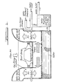
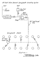
- Figure 1 shows schematically one type of spraybooth with associated water wash.
- Workpieces e.g., autobodies, such as in Figure 1
- Relatively clean air enters the booth downwardly and perpendicular to the workpieces and grate.
- the relatively clean air draws subsisting airborne components of the coating composition through the grate into the water wash.
- the water wash comprises a wet scrubber that takes particulate, and in the case of this invention, an amount of certain volatile organic compounds from the air.
- This invention particularly concerns use of high volume, low energy wet scrubbers that operate at inlet and outlet pressure differences below about 2491 Pa (10 inches of water) and even as low as below 1494 Pa (6 inches of water), e.g. 249-1245 Pa (1-5 inches of water) pressure difference.
- the pressure drop may be determined by pressure measurements at convenient locations within the water wash. For example measurements may be made at locations of just before first water contact and just after last water contact in the water wash; the difference of these measurements is a measure of pressure difference.
- Water flow in the water wash may vary. Normally it will be 63-1260 litres per minute per linear meter (5-100 gallons per minute per linear foot) of the spraybooth. Countercurrent air and water flows in the water wash are preferred in accordance with the invention; water washes with concurrent air and water flows should, however, also be suitable.
- the sprayable coating composition is selected to be a scrubbable coating composition.
- a scrubbable coating composition comprises a scrubbable compound.
- Preferred scrubbable compounds comprise oxygenated compounds. More preferred scrubbable compounds are selected from the group consisting of esters, ethers and alcohols. Examples of the esters are mono and di esters such as acetates, adipates, glutarates, succinates and the like. More specifically, examples are cellosolve acetate (i.e. ethylene glycol monoethyl ether acetate), methyl cellosolve acetate (i.e. ethylene glycol monomethyl ether acetate), butyl cellosolve acetate (i.e.
- ethylene glycol monobutyl ether acetate ethylene glycol monobutyl ether acetate
- butyl acetate ethyl carbitol acetate (i.e., diethylene glycol monoethyl ether acetate), butyl carbitol acetate (i.e. diethylene glycol monobutyl ether acetate).
- the alcohols are amino alcohols such as alkanol amines, ester alcohols, and ether alcohols. More specific examples of alcohols are triethanol amine, butyl carbitol (i.e., diethylene glycol monobutyl ether), cellosolve (i.e. ethylene glycol monoethyl ether), methyl cellosolve (i.e.
- ethylene glycol monomethyl ether ethylene glycol monomethyl ether
- butanol ethylene glycol
- ethylene glycol ethylene glycol monomethyl ether
- ether diethyl carbitol (ethylene glycol diethyl ether).
- scrubbable compounds are suitable for use in aqueous and non-aqueous coating compositions at desired levels.
- the most desired level is as high a percentage of scrubbable compounds of the volatile organic compound in the coating composition as possible, taking into account other factors in usual coating composition formulation.
- aqueous and non-aqueous coating compositions are those including thermoplastics, and/or thermosets which, in turn, may be topcoats, sealers, primers, etc.
- the process of this invention further includes capture of scrubbable compounds by the scrubbing water in the water wash.
- Sprubbing water as used herein means water in the water wash that comes into scrubbable contact with airborne components of a sprayable coating composition. This contact is, for example, between water of a venturi spray or water curtain or other high volume, low energy scrubber gas-water interface and the airborne components.
- scrubbing water typically contains water treatment compounds.
- the process of this invention has not been found to detract from function or employment of typical water treatment compounds.
- water treatment compounds that act to "kill" paint overspray. It includes water treatment compounds that may act to detactify, coagulate, precipitate, float or otherwise treat paint overspray. It still further includes water treatment compounds that are surfactants, anti corrosion agents, bacteriocides, fungicides, etc. Examples of water treatment compound formulations include those in U.S. Patents 3,985,955; 4,002,490; 4,090,001; 4,125,576; 4,130,674 and Canadian Patent 589,560.
- Especially preferred water treatment compound formulations include amines, aluminates, silicates and the like at a variety of basic pH levels.
- the aqueous phase of the scrubbing water has a pH between 7-14, more preferably between about 9.5-11.5.
- Modifiers of pH may be added on a continuous basis to circulating scrubbing water.
- Examples of commercially available water treatment compounds are those identified as Nalco 8724 containing polyelectrolyte; Nalco 8723 containing polyelectrolyte; Nalco 2 containing sodium aluminate, and Nalco 8735.
- water treatment compounds may be removed along with treated overspray by conventional means.
- the process of this invention preferably includes such a removal and an addition of make up water treatment compounds.
- the scrubbing water has a concentration of scrubbable compound below that which reduces efficiency below about 10% of a maximum efficiency. Normally, such an amount is below 50 grams/liter of scrubbable compound, e.g., between about 0.1-20 grams/liter. Maximum efficiency, however, is when the scrubbing water is essentially free of any scrubbable compound.
- Preferred scrubbable coating compositions comprise a scrubbable compound that boils above about 120°C. Uptake by the scrubbing water of such a preferred scrubbable compound continues with a desirable efficiency even when the scrubbing water contains higher levels of scrubbable compounds within the above ranges.
- Removal of scrubbable compounds from scrubbing water may be by biological, physicochemical or biological and physicochemical processes; alternatively, the scrubbing water may be simply replaced with fresher (e.g., municipal) water.
- physicochemical processes include coagulation, precipitation, filtration, adsorption, ion exchange, membrane separation, and chemical oxidation.
- the sprayable coating composition is selected to be a scrubbable coating composition, i.e., comprise a scrubbable compound.
- a scrubbable coating composition i.e., comprise a scrubbable compound.
- the pressure drop of the water wash affects efficiency. Higher pressure drops cause more efficient uptake of scrubbable compounds. Further, lower levels of scrubbable compounds in the scrubbing water allows higher efficiencies.
- the scrubbing water generally retains higher boiling scrubbable compounds longer than lower boiling scrubbable compounds, assuming equal solubilities. Similarly, the scrubbing water generally retains more water soluble scrubbable compounds longer then less water soluble scrubbable compounds, assuming equal boiling points.
- the amount of emissions abated in accordance with this invention may be generally added to the amount of abatement achieved by these other factors.
- these other factors include (1) solids content of the coating composition, (2) transfer efficiency of spray application, e.g., mode of spraying and (3) manner of handling emissions from bake ovens, e.g. incineration by catalyst.
- Table 2 shows solvent composition and physical properties of sprayable coating compositions used in the three trials.
- Trial 1 examined high solids enamel 3760;
- Trial 2 examined non-aqueous dispersion enamel 5180;
- Trial 3 examined high solids enamel 3742.
- a Binks Model 61 automatic spraygun equipped with a 63C fluid nozzle and 63PR air cap sprayed paint at a rate in each trial of 0.03 litres of solids per minute per linear meter (0.002 gallons of solids per minute per linear foot) of back section.
- the spraygun actuated automatically on a 15 second cycle, operated with open gun times ranging between 2 and 4 seconds in each cycle.
- the spraygun nozzle was diagonally five feet from the air inlet of the back section.
- the spray from the nozzle was in a vertical fan shape and at approximately -45° from horizontal. Mounting the pressure pot of the spraygun on a scale enabled the spray rate to be monitored and controlled.
- a Beckman Model 402 Total Hydrocarbon (THC) Analyzer continuously monitored stack emissions.
- An Omniscribe Model B5217-5 two-channel recorder simultaneously displayed instantaneous and electronically integrated (over ten, 15 second spray periods) output from the analyzer.
- the THC analyzer was zeroed with Ultra Zero Air (Air Monitoring, Inc.) and spanned with 80 and 204 ppm propane-in-air standards ( ⁇ 1% accuracy, Accublend, Scott Research Company) approximately every five hours. Samples of stack emissions passed anisokinetically through a twelve foot stainless steel line to the analyzer during the first trial. Heat tracing occurred over all but a two- foot, in-stack section of this sample line. In the other trials, the system shown in Figure 3 isokinetically sampled stack emissions.
- Dupont Model 4000 constant flow, personnel sampling pumps collected known volumes of air emissions directly from the spraybooth exhaust stack onto traps containing Tenax GC polymer. Selection of sampling times averaged rapid temporal changes in stack emission levels.
- the inlet of a Hewlett Packard Model 5711A Gas Chromatograph equipped with a flame ionization detector (FID) received heat desorbed samples from the traps.
- FID flame ionization detector
- samples came from the sample bypass stream of the Beckman 402 THC Analyzer. Sampling occurred approximately every two hours in these trials. (A Hewlett Packard 3385A integration system) reduced the 5711 A data in all trials.
- a Perkin Elmer Sigma 1 GC system equipped with a flame ionization detector (FID) measured uptake of specific solvents into the spraybooth water. Collection of booth water grab samples occurred every ninety minutes in 25 ml headspace-free vials fitted with teflon lined caps. After centifugation to remove suspended solids, there was direct aqueous injection into the Sigma GC.
- FID flame ionization detector
- a Hewlett Packard 5992B GC-MS system provided qualitative confirmation of solvent identity of spraybooth water, sludge and air emissions. Sampling techniques were identical to those in GC analysis.
- Spraybooth exhaust flow measurements were in accordance with Ford Manufacturing Standards BAX-2 procedures.
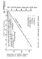
- Figures 5, 6 and 7 illustrate an increase in the amount of solvent compounds in booth water as a function of paint spraying time for pilot trials I, II and III, respectively.
- Non-polar compounds like xylene and esposol 260 did not appear appreciably in the booth water.
- Figures 5, 6 and 7 express cellosolve acetate by combining cellosolve acetate and its hydrolysis product cellosolve.
- Tables 8, 9 and 10 show solvent concentration (corrected to 7448 Pa (760 mm Hg), 20°C) at selected times during each of the three pilot trials.
- the weight per unit volume solvent concentrations are also recalculated as their equivalent total hydrocarbon concentration in terms of propane. These totals are compared to actual THC concentrations measured by the Beckman 402 Analyzer. The calculations used carbon number response factors derived from the literature or from empirical results.
- Tables 11, 12 and 13 show results of analysis of bottom and floating sludges taken during Trials I, II and III, respectively.
- Tables 14, 15 and 16 present material balances for several sampling periods during Pilot Trials I, 11 and III, respectively. For each sampling period, solvent spray rate versus solvent emission and capture rate is presented. The materials balances range between 81 and 102 percent.
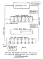
- FIG. 4 shows schematically pertinent portions of spraybooth, water line and stack arrangement of the AP painting process.
- electrocoated vehicle bodies passed sequentially through a Prime Spraybooth, a Prime Bake Oven, a West Main Enamel Booth, an East Main Enamel Booth, a Main Enamel Bake Oven, and, if required, a Tutone-Repair Spray Booth and Bake Oven.
- Manual spray equipment thereafter sprayed gray primer around vehicle door jambs and rocker panel areas.
- the manual spray equipment sprayed the remaining amount of taupe primer.
- the vehicles then exited the Prime Spraybooth and entered the Prime Bake Oven.
- the Prime Spraybooth stacks for example, exhausted n-butyl acetate and butyl cellosolve even though these solvents arose from spraying in the East Main Enamel Booth.
- the east water pit held 170,000 ⁇ 5000 gallons (642600 ⁇ 18900 litres) during the two production trials. At the beginning of each trial, the water showed essential freedom of solvent. The retention time of water in the east water pit was about 10 minutes. Metering of Nalco 8724 to the water was at a rate of about 1.5 gallons per hour. The water had a basic pH which was in a range between 10-10.5 through most of the trials. A combination of manual and constant metered additions of caustic (50%) maintained the pH.
- the first trial examined emission from taupe primer 119B; the trial lasted two days.
- the second trial examined primer 120C; it lasted four days.
- Table 5 shows the cellosolve acetate concentration of the 119B and 120C coatings and enamels sprayed in the East Main Enamel Booth along with the volume of each coating sprayed daily.
- a heat-traced manifold system provided an average sample from all 10 stacks on the Prime Spraybooth to a Beckman Model 402 THC Analyzer.
- a second, heat-traced manifold system provided an average sample from seven of the fourteen East Main Enamel Spraybooth stacks to a Beckman 400 THC Analyzer. Total hydrocarbon measurements made on all 14 enamel booth stacks determined that the emission rate from the seven stacks monitored during the trial was equivalent to the seven not monitored.
- GC determined the emission rates of specific solvents in stack emissions from the Prime Spraybooth, the Prime Bake Oven and the East Main Enamel Booth.
- Dupont Model 4000 constant flow personnel sampling pumps collected known volumes of hydrocarbon vapor onto traps containing Tenax GC polymer. Samples came from the FID bypass streams on the three THC Analyzers used to monitor the Prime Booth, Prime Bake Oven, and East Main Enamel Stack Systems. Sampling frequency, flow, time and gas chromatograpic system used for analyzing samples appear in Table 6.
- the Hewlett Packard Model 5711A gas chromatograph was the same instrument used in the pilot plant trials except that a Perkin Elmer Sigma 1 Data System reduced the data.
- a heat-traced stainless steel manifold systm provided an average emission sample from the ten prime spraybooth stacks.
- Figure 11 illustrates sampling point on each stack.
- 6.3 mm (1/4") i.d. sections of line (Technical Heaters, Inc. Model 500-1/4) linked each stack to a central 9.5 mm (3/8") i.d. trunk line (Technical Heaters, Inc. Model 500-3/8) leading to the Beckman 402 THC analyzer.
- a Technical Heaters, Inc. Model 10450 Temperature Controller maintained the 6.3 mm (1/4") sample lines at approximately 149°C (300°F) and the 9.5 mm (3/8") lines at approximately 110°C (230°F).
- a Metal Bellows Model 302HT pump provided sample flow.
- An Associated Testing Laboratories, Inc. Model BP-1102 oven maintained pump temperature at 140°C (285°F) to prevent sample condensation.
- the effluent from the pump was split. Approximately 1.9 I/min of flow went to the THC analyzer and the remaining flow vented through a S-110 dry test meter.
- the Beckman 402 THC Analyzer was modified so that flow from the glass fiber filter bypassed the internal metal bellows pump and went directly to the FID capillary-splitter.
- the THC analyzer was zeroed with Ultra Zero Air (Air Monitoring, Inc.) and spanned with an 80 ppm propane-in-air standard approximately every four hours. An additional two-point calibration was performed daily with 80 and 204 ppm propane-in-air standards (11% accuracy, Scott Research Co.). The output from the THC analyzer was recorded directly and was also electronically integrated over periods of 10.0 minutes. An Omniscribe Model B5217-5 two-pen recorder recorded both outputs continuously.
- a heat-traced stainless manifold system provided on average emission sample GC and THC analysis from seven of the fourteen East Main Enamel Spraybooth stacks (Figure 14). The sampling point on each stack is illustrated in Figure 11.
- the heat-traced sample lines and the associated temperature and flow control equipment used on the East Main Enamel Booth were identical to the equipment used on the Prime Spraybooth ( Figure 12, 13).
- a Metal Bellows Model 158HT pump provided sample flow. Heat tracing of the pump head and the sample lines leading to the FID detector on the Beckman 400 THC Analyzer prevented sample condensation. Effluent from the pumps was split. Approximately 2.2 I/min of flow went to the THC analyzer and the remaining flow vented through a Rockwell Model S-1 10 dry test meter ( Figure 14).
- the Beckman 400 THC Analyzer was zeroed with Ultra Zero Air (Air Monitoring, Inc.) and spanned with 204 ppm propane-in-air standard approximately every four hours H 1 % accuracy, Scott Research Co.).
- An Omniscribe Model B51 18-4 strip chart recorder recorded continuously the output from the THC analyzer.
- a Beckman 402 THC Analyzer monitored emissions from the single stack on the Prime Bake Oven. Samples of the emissions passed through an eleven foot heat-traced line supplied with the THC analyzer. The instrument was zeroed with Ultra Zero Air (Air Monitoring Inc.) and spanned with 204 ppm propane-in-air standard ( ⁇ 1% accuracy, Scott Research Co.) approximately every four hours. A Weather Measure Model EPR-200A strip chart recorder recorded continuously the output from the THC analyzer.
- a Perkin Elmer Sigma 1 Gas Chromatographic System measured solvents in the water of the East Pit System. Booth water grab samples occurred approximately every 2.5 hours in 25 ml headspace-free vials fitted with teflon-lined caps. The GC received the samples (after centrifugation to remove suspended solids) by direct aqueous injection.
- a Hewlett Packard 5992B GC-MS System analyzed the Prime Spraybooth, Prime Bake Oven, East Main Enamel Stack Emissions, and East Pit System Water prior to the trials.
- Figures 8 and 9 illustrate uptake of specific solvents into the water of the AP East. Pit-System during the 119B and the 120C taupe primer trials as a function of paint spraying time. Figures 8 and 9 express results as increasing booth water concentration and as mass of solvent captured. Least squares regression analysis gave cellosolve acetate accumulation in the booth water at a rate of 4.5+0.3 kg/hr of spraytime during the 119B trial and at 11.910.2 kg/hr during the 120C trial.
- the solvent pentoxane accumulated in the booth water during both trials. It was a constituent of a cleaning/purge solvent blend and not contained in any primer or enamel solvent package.
- Table 17 and Tables 18, 19 and 20 show daily average stack emission rate for specific solvents from the Prime Spraybooth, the Prime Bake Oven, and the East Main Enamel Spraybooth during the 119B and 120C trials, respectively.
- the tables express emission rates in terms of kilograms of solvent emitted per hour of paint spraying time (corrected to 20°C, 7445 Pa (29.9" Hg. Calculations account for daily differences in stack flows (Table 4).
- the tables express average concentration of each solvent in milligrams per cubic meter (standard conditions: 7445 Pa (29.9" Hg), 20°C); and the total concentration is reexpressed in terms of propane (C 3 H 8 ) and compared to the daily average THC concentrations measured at each source with either a Beckman 400 or 402 Analyzer. The difference between the measured and calculated THC concentrations for the Prime and Enamel Spraybooths seldom exceeded 10 percent. Fluctuations in the measured THC values through each day, however, frequently exceeded this level.
- Table 21 shows material balances on the cellosolve acetate sprayed in the East Pit Water System during the 119B and 120C trials.
- the material balance compares the sum of emission rates from the Prime Spraybooth, Prime Bake Oven and the East Main Enamel Spraybooth plus the rate of cellosolve acetate captured in the booth water (absent sludge) to the rate at which cellosolve acetate was sprayed in the Prime and East Main Enamel Spraybooth.
- the percentage of cellosolve acetate captured in the spraybooth water was 28 ⁇ 5% and 29+5% of the total sprayed in the 119B and 120C trials, respectively. Efficiency appears closer to 32+6% when considering the amount of cellosolve acetate in the sludge and the minor amounts of solvent other than cellosolve acetate captured in the spraybooth water. This capture efficiency translates into a 5% reduction in VOC for the 119B coating and a 19% reduction in VOC for the 120C coating.
- Table 22 compares Prime Spraybooth stack volatile organic compound emission rate to spray rate. An efficiency in the first trial can not be based on this data because the emission rate exceeds the spray rate. An efficiency in the second trial (emitted over sprayed) is 13%. Error analysis, however, suggests the latter result neither proves nor disproves reduction of emissions because errors in the measurements involved in the material balance were +22%.
- Figure 10 gives an example of how backsection scrubbing abatement might be used, in part, to reduce the equivalent emissions (VOC) of a 120C solvent based primer and assuming abatement by the various techniques is additive.
- This solvent based primer applied unabated using non-electrostatic spray equipment has a VOC of 0.48 kg/I (4.8 Ib/gal).
- VOC equivalent emissions
- Nalco 8735 and 8724 have the following characteristics: Infrared analysis:
- Spectrograms of #8735 are characteristic of Sodium Carbonates.
- Spectrograms of #8724 are characteristic of Carbonates.
- 8724 compound is believed to be 10% by weight of polyamine synthesized from the following materials:
Landscapes
- Chemical & Material Sciences (AREA)
- Chemical Kinetics & Catalysis (AREA)
- Application Of Or Painting With Fluid Materials (AREA)
- Separation Of Particles Using Liquids (AREA)
- Coating Apparatus (AREA)
Abstract
Description
- This invention relates to a process of coating a workpiece
- In industrial spraybooths, workpieces may be coated by the manual or automatic application of sprayable coating compositions. Not all the coating composition, however, associates with the workpieces. Rather, certain airborne components of the coating composition subsist in the atmospheric gases of the spraybooth.
- Large volumes of air draw these airborne components to low energy, wet scrubbers. These scrubbers remove particulate material from the air. The problem of other airborne components especially volatile organic compounds normally forming the solvent or carrier for the composition, still remains.
- It has been suggested by some that reduction of emission of volatile organic compounds from industrial spraybooths requires extensive hardware modification. Others suggest employment of water base, powder or significantly higher solids coating formulations.
- In accordance with this invention, however, high volume, low energy, wet scrubbers now commonly associated with industrial spraybooths, may be operated in a manner that captures certain volatile organic compounds from airborne components that enter the water wash.
- According to the present invention, there is provided a process for coating a workpiece which comprises spraying the workpiece in a spraybooth with a coating composition comprising a volatile organic compound having a boiling point of at least 98°C at normal atmospheric pressure and having a solubility in water of at least 6% by weight at 20°C; and scrubbing the atmospheric gases of the spraybooth with an aqueous scrubbing medium capable of capturing the volatile organic compound; characterised in that the concentration of said volatile organic compound in said aqueous scrubbing medium is adjusted during the coating process so that it does not exceed a concentration above that which causes the rate of removal of volatile organic compound from the atmospheric gases to be less than 10% of the rate of removal of the volatile organic compound from the atmospheric gases by the aqueous scrubbing medium when free from the volatile organic compound.
- By controlling the concentration of volatile organic compound in the aqueous scrubbing medium, the efficiency with which volatile organic compounds are removed from the atmospheric gases of the spraybooth can be increased without extensive modification of the equipment.
- The amount of the volatile organic compounds captured will normally be at least 10% by weight of the weight of the particular volatile organic compound sprayed into the spraybooth, but can be as high as 90% by weight thereof.
- The concentration of volatile organic compound in the aqueous scrubbing medium may be controlled by biologically and/or physiochemically removing a portion of the volatile organic compound from the scrubbing water.
- Preferably concentration of volatile organic compound in the scrubbing medium should not exceed 50 grams per litre, and is desirably no more than 25 grams per litre, (e.g. 0.1-25 g/L).
- The volatile organic compound contained in the coating composition preferably comprises an ester, alcohol, ether or any combination thereof. In one embodiment, the scrubbable coating composition is an etherially linked ester, such as cellosolve acetate.
- Spraying of the sprayable coating composition may be by electrostatic application or otherwise; electrostatic application, however, offers additional benefits of higher transfer efficiency than normally achieved by conventional application.
- Embodiments of the invention will now be described, by way of example only, with reference to the accompanying drawings, in which:-
- Figure 1 illustrates in schematic form one type of paint spray booth with associated (in this case integral) water back sections that may be operated in accordance with this invention. Associated hardware such as pumps, valves, filters, scrubbing devices, etc. have been omitted for simplicity and greater clarity.
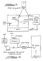
- Figure 2 illustrates a pilot scale spraybooth with integral water wash back section. This pilot scale spraybooth was used in Pilot Trails I, II, and III in the examples.
- Figure 3 is a schematic of the total hydrocarbon content (THC) and gas chromatography (GC) sampling systems of the Pilot Spraybooth of Figure 2.
- Figure 4 is a schematic of east water pit system, air sampling lines and analyzers monitored in the assembly plant (AP) trial of the examples.
- Figures 5, 6 and 7 are graphs showing solvent uptake in scrubbing water in Pilot Trials I, II and III respectively.
- Figures 8 and 9 are graphs showing uptake by scrubbing water during the AP trials using 119B and 120C coating compositions respectively.
- Figure 10 is a graph showing the effects of scrubbing during the AP trial using
coating composition 120C. - Figure 11 shows schematically the AP stack sampling port and flow measurement port locations.
- Figure 12 shows the AP prime spraybooth stack sampling system.
- Figure 13 shows the AP stack sample manifold flow regulation system.
- Figure 14 shows the AP east main enamel spraybooth stack sampling system.
- "Scrubbable compound" as used on the following description refers to a volatile organic compound which (1) boils above about 98°C at atmospheric pressure and (2) has a water solubility of at least 6% by weight at 20°C.
- Paint spraybooths having a water wash associated therewith are widely used. Although such booths and water washes vary with respect to design and size, they conventionally comprise a low energy, high volume wet scrubber. The wet scrubber permits contact between scrubbing water and airborne emissions from spray painting in the booth.
- For example, Figure 1 shows schematically one type of spraybooth with associated water wash. Workpieces, e.g., autobodies, such as in Figure 1, enter and exit the spraybooth along a line perpendicular to the spray of a sprayable coating composition and along a grate opening to the water wash. Relatively clean air enters the booth downwardly and perpendicular to the workpieces and grate. The relatively clean air draws subsisting airborne components of the coating composition through the grate into the water wash. The water wash comprises a wet scrubber that takes particulate, and in the case of this invention, an amount of certain volatile organic compounds from the air. The air enters the water wash at a rate of 1415-16980 cubic meters per minute per linear meter (cmm/m) (250-3000 cubic feed per minute per linear foot (cfm/ft)) of the booth, and more usually 2830-8490 cmm/m (500-1500 cfm/ft).
- This invention particularly concerns use of high volume, low energy wet scrubbers that operate at inlet and outlet pressure differences below about 2491 Pa (10 inches of water) and even as low as below 1494 Pa (6 inches of water), e.g. 249-1245 Pa (1-5 inches of water) pressure difference. The pressure drop may be determined by pressure measurements at convenient locations within the water wash. For example measurements may be made at locations of just before first water contact and just after last water contact in the water wash; the difference of these measurements is a measure of pressure difference.
- Another way to characterize conventional spraybooth wet scrubbers is by what is referred to as amount of particulate that emits after wet scrubbing. For example, certain booths operate at what is often termed as "3" or "5 grain" particulate scrubbing efficiency. "Grain" refers to the amount of particulate per unit volume of air, e.g., 1 grain equals 0.0648 grams standard cubic feet per minute.
- Water flow in the water wash may vary. Normally it will be 63-1260 litres per minute per linear meter (5-100 gallons per minute per linear foot) of the spraybooth. Countercurrent air and water flows in the water wash are preferred in accordance with the invention; water washes with concurrent air and water flows should, however, also be suitable.
- In the process of this invention, there is selection with respect to the type of sprayable coating composition sprayed. More particularly, the sprayable coating composition is selected to be a scrubbable coating composition. A scrubbable coating composition comprises a scrubbable compound.
- Preferred scrubbable compounds comprise oxygenated compounds. More preferred scrubbable compounds are selected from the group consisting of esters, ethers and alcohols. Examples of the esters are mono and di esters such as acetates, adipates, glutarates, succinates and the like. More specifically, examples are cellosolve acetate (i.e. ethylene glycol monoethyl ether acetate), methyl cellosolve acetate (i.e. ethylene glycol monomethyl ether acetate), butyl cellosolve acetate (i.e. ethylene glycol monobutyl ether acetate), butyl acetate, ethyl carbitol acetate (i.e., diethylene glycol monoethyl ether acetate), butyl carbitol acetate (i.e. diethylene glycol monobutyl ether acetate). Examples of the alcohols are amino alcohols such as alkanol amines, ester alcohols, and ether alcohols. More specific examples of alcohols are triethanol amine, butyl carbitol (i.e., diethylene glycol monobutyl ether), cellosolve (i.e. ethylene glycol monoethyl ether), methyl cellosolve (i.e. ethylene glycol monomethyl ether), butanol and ethylene glycol. An example of the ether is diethyl carbitol (ethylene glycol diethyl ether). (For convenience hereinafter, any compound, however, comprising an ester group shall be considered an ester; any compound not comprising an ester group but having an ether group shall be considered an ether).
- Advantageously, scrubbable compounds are suitable for use in aqueous and non-aqueous coating compositions at desired levels. The most desired level is as high a percentage of scrubbable compounds of the volatile organic compound in the coating composition as possible, taking into account other factors in usual coating composition formulation. Examples of aqueous and non-aqueous coating compositions are those including thermoplastics, and/or thermosets which, in turn, may be topcoats, sealers, primers, etc.
- The process of this invention further includes capture of scrubbable compounds by the scrubbing water in the water wash. "Scrubbing water" as used herein means water in the water wash that comes into scrubbable contact with airborne components of a sprayable coating composition. This contact is, for example, between water of a venturi spray or water curtain or other high volume, low energy scrubber gas-water interface and the airborne components.
- As is well known, scrubbing water typically contains water treatment compounds. The process of this invention has not been found to detract from function or employment of typical water treatment compounds.
- The usual function of water treatment compounds is to enhance and maintain the ability of scrubbing water to "knock down" or otherwise take particulate from air passing through the water wash. This function includes water treatment compounds that act to "kill" paint overspray. It includes water treatment compounds that may act to detactify, coagulate, precipitate, float or otherwise treat paint overspray. It still further includes water treatment compounds that are surfactants, anti corrosion agents, bacteriocides, fungicides, etc. Examples of water treatment compound formulations include those in U.S. Patents 3,985,955; 4,002,490; 4,090,001; 4,125,576; 4,130,674 and Canadian Patent 589,560.
- Especially preferred water treatment compound formulations include amines, aluminates, silicates and the like at a variety of basic pH levels. Preferably, however, the aqueous phase of the scrubbing water has a pH between 7-14, more preferably between about 9.5-11.5. Modifiers of pH may be added on a continuous basis to circulating scrubbing water.
- Examples of commercially available water treatment compounds are those identified as Nalco 8724 containing polyelectrolyte; Nalco 8723 containing polyelectrolyte;
Nalco 2 containing sodium aluminate, and Nalco 8735. - Having served a function of treatment of paint overspray, water treatment compounds may be removed along with treated overspray by conventional means. The process of this invention preferably includes such a removal and an addition of make up water treatment compounds.
- In order that capture by the scrubbing water of scrubbable compound continue in the process of this invention, the scrubbing water has a concentration of scrubbable compound below that which reduces efficiency below about 10% of a maximum efficiency. Normally, such an amount is below 50 grams/liter of scrubbable compound, e.g., between about 0.1-20 grams/liter. Maximum efficiency, however, is when the scrubbing water is essentially free of any scrubbable compound.
- Preferred scrubbable coating compositions comprise a scrubbable compound that boils above about 120°C. Uptake by the scrubbing water of such a preferred scrubbable compound continues with a desirable efficiency even when the scrubbing water contains higher levels of scrubbable compounds within the above ranges.
- Removal of scrubbable compounds from scrubbing water may be by biological, physicochemical or biological and physicochemical processes; alternatively, the scrubbing water may be simply replaced with fresher (e.g., municipal) water. Examples of physicochemical processes include coagulation, precipitation, filtration, adsorption, ion exchange, membrane separation, and chemical oxidation.
- In preferred applications of principles of the invention, several factors play a role in coating composition selection. As mentioned, the sprayable coating composition is selected to be a scrubbable coating composition, i.e., comprise a scrubbable compound. Of course, the higher the level of scrubbable compounds in the organic solvents employed, the more emissions that may be abated.
- The pressure drop of the water wash affects efficiency. Higher pressure drops cause more efficient uptake of scrubbable compounds. Further, lower levels of scrubbable compounds in the scrubbing water allows higher efficiencies.
- Still other factors that may be considered include the boiling temperature of the scrubbable compound. The scrubbing water generally retains higher boiling scrubbable compounds longer than lower boiling scrubbable compounds, assuming equal solubilities. Similarly, the scrubbing water generally retains more water soluble scrubbable compounds longer then less water soluble scrubbable compounds, assuming equal boiling points.
- In these preferred applications, other factors, may affect emissions from the water wash. The amount of emissions abated in accordance with this invention may be generally added to the amount of abatement achieved by these other factors. Examples of these other factors include (1) solids content of the coating composition, (2) transfer efficiency of spray application, e.g., mode of spraying and (3) manner of handling emissions from bake ovens, e.g. incineration by catalyst.
- There were three pilot plant (AP-PP) trials. The spraybooth in each trial was a five-foot, side-draft spraybooth manufactured by Binks Manufacturing Company; it had a H.R. Black Company Model PDSB paint sludge filter system. Schematic representation of the spraybooth test assembly appears in Figure 2; operating parameters for each trial appear in Table 1.
- Operation in accordance with manufacturer's specifications suggested that the back section had a 3 grain efficiency during the first two trials and a 5 grain efficiency during the last trial.
- Table 2 shows solvent composition and physical properties of sprayable coating compositions used in the three trials.
Trial 1 examined high solids enamel 3760;Trial 2 examined non-aqueous dispersion enamel 5180;Trial 3 examined high solids enamel 3742. - A Binks Model 61 automatic spraygun equipped with a 63C fluid nozzle and 63PR air cap sprayed paint at a rate in each trial of 0.03 litres of solids per minute per linear meter (0.002 gallons of solids per minute per linear foot) of back section. The spraygun, actuated automatically on a 15 second cycle, operated with open gun times ranging between 2 and 4 seconds in each cycle.
- The spraygun nozzle was diagonally five feet from the air inlet of the back section. The spray from the nozzle was in a vertical fan shape and at approximately -45° from horizontal. Mounting the pressure pot of the spraygun on a scale enabled the spray rate to be monitored and controlled.
- A Nalco Model V-6 mini-pump metered Nalco 8724 water treatment compound continuously into the spraybooth water; metering was proportional to paint spray rate. A Great Lakes Instruments, Inc. (GLI) Model A605421 A pH monitor/controller used with a GLI Model P60L-4-1 submergible pH probe and a Nalco Model V6 mini-pump controlled booth water pH automatically by addition of
Nalco 2 or Nalco 8735 water treatment compounds. Addition of Nalco 71-D6 defoaming compounds as required and in 80 ml aliquots controlled foam in the first two trials; a FMI Model RP-6400 pump continuously metered the 71-D6 into the booth water in the last trial. Other spraying conditions and chemical addition rates appear in Table 3. - A Beckman Model 402 Total Hydrocarbon (THC) Analyzer continuously monitored stack emissions. An Omniscribe Model B5217-5 two-channel recorder simultaneously displayed instantaneous and electronically integrated (over ten, 15 second spray periods) output from the analyzer.
- The THC analyzer was zeroed with Ultra Zero Air (Air Monitoring, Inc.) and spanned with 80 and 204 ppm propane-in-air standards (±1% accuracy, Accublend, Scott Research Company) approximately every five hours. Samples of stack emissions passed anisokinetically through a twelve foot stainless steel line to the analyzer during the first trial. Heat tracing occurred over all but a two- foot, in-stack section of this sample line. In the other trials, the system shown in Figure 3 isokinetically sampled stack emissions.
- GC analyses determined emission rates of specific solvents. Dupont Model 4000 constant flow, personnel sampling pumps collected known volumes of air emissions directly from the spraybooth exhaust stack onto traps containing Tenax GC polymer. Selection of sampling times averaged rapid temporal changes in stack emission levels. The inlet of a Hewlett Packard Model 5711A Gas Chromatograph equipped with a flame ionization detector (FID) received heat desorbed samples from the traps.
- In other trials, samples came from the sample bypass stream of the Beckman 402 THC Analyzer. Sampling occurred approximately every two hours in these trials. (A Hewlett Packard 3385A integration system) reduced the 5711 A data in all trials.
- A
Perkin Elmer Sigma 1 GC system equipped with a flame ionization detector (FID) measured uptake of specific solvents into the spraybooth water. Collection of booth water grab samples occurred every ninety minutes in 25 ml headspace-free vials fitted with teflon lined caps. After centifugation to remove suspended solids, there was direct aqueous injection into the Sigma GC. - A Hewlett Packard 5720 Gas Chromatograph equipped with a Unacon Model 780 sample introduction system and a Hewlett Packard Model 3380S integrator analyzed sludge samples. Airtight containers stored frozen grab samples of floating and sunken sludge.
- A Hewlett Packard 5992B GC-MS system provided qualitative confirmation of solvent identity of spraybooth water, sludge and air emissions. Sampling techniques were identical to those in GC analysis.
- Spraybooth exhaust flow measurements were in accordance with Ford Manufacturing Standards BAX-2 procedures.
- Figures 5, 6 and 7 illustrate an increase in the amount of solvent compounds in booth water as a function of paint spraying time for pilot trials I, II and III, respectively. Non-polar compounds like xylene and esposol 260 did not appear appreciably in the booth water.
- Figures 5, 6 and 7 express cellosolve acetate by combining cellosolve acetate and its hydrolysis product cellosolve.
- Tables 8, 9 and 10 show solvent concentration (corrected to 7448 Pa (760 mm Hg), 20°C) at selected times during each of the three pilot trials. In these tables, the weight per unit volume solvent concentrations are also recalculated as their equivalent total hydrocarbon concentration in terms of propane. These totals are compared to actual THC concentrations measured by the Beckman 402 Analyzer. The calculations used carbon number response factors derived from the literature or from empirical results.
- Tables 11, 12 and 13 show results of analysis of bottom and floating sludges taken during Trials I, II and III, respectively.
- Tables 14, 15 and 16 present material balances for several sampling periods during Pilot Trials I, 11 and III, respectively. For each sampling period, solvent spray rate versus solvent emission and capture rate is presented. The materials balances range between 81 and 102 percent.
- An assumption for the calculations in Tables 14, 15 and 16 is that the sludge had a composition as presented in Tables 11, 12 and 13, respectively. The sludge production rate was estimated from weight solids of each original paint since all the paint solids sprayed during the pilot trials entered the back section.
- At operation of the back section at 1220 Pa (4.9 inches) pressure drop (3-grain (194 mg) particulate scrubbing efficiency), there was removal by cellosolve acetate at 80% efficiency. At operation of the back section at 647 Pa (2.6 inches) pressure drop (5-grain (324 mg) efficiency), there was removal of cellosolve acetate at 55% efficiency. Table 7 shows cumulative scrubbing efficiencies for cellosolve acetate and butyl carbitol over selected spray periods.
- The production trials were under conditions of commercial spray painting of automobiles in an automotive assembly plant (AP). During the production trials, approximately 62 vehicles per hour received prime and top coats. Figure 4 shows schematically pertinent portions of spraybooth, water line and stack arrangement of the AP painting process.
- In the AP coating operation, electrocoated vehicle bodies passed sequentially through a Prime Spraybooth, a Prime Bake Oven, a West Main Enamel Booth, an East Main Enamel Booth, a Main Enamel Bake Oven, and, if required, a Tutone-Repair Spray Booth and Bake Oven.
- In a west end of the Prime Spraybooth, modified Behr-Ransbury equipment electrostatically sprayed approximately 50% of a taupe primer. Stacks 9 and 10 (Figure 4) exhaust the west end.
- Manual spray equipment thereafter sprayed gray primer around vehicle door jambs and rocker panel areas. The manual spray equipment sprayed the remaining amount of taupe primer. A total of 10 stacks and fans exhausted the Prime Spraybooth.
- The vehicles then exited the Prime Spraybooth and entered the Prime Bake Oven. The residence time in the Prime Bake Oven was about 21 minutes. A single stack exhausted the Prime Bake Oven.
- Vehicles next entered the West Main Enamel Booth. Behr-Este equipment and four spraypersons sprayed, respectively, electrostatically and manually, topcoat in the West Main Enamel Booth.
- Vehicles then entered the adjoining East Main Enamel Booth. Ten to twelve spraypersons sprayed remaining exterior and interior topcoats in the East Main Enamel Booth. Fourteen stacks and fans exhausted the East Main Enamel Booth.
- Stack exhaust flows for the Prime Spraybooth, the Prime Bake Oven, and the East Main enamel Booth appear in Table 4.
- Although the East and West Enamel Booths adjoined one another, their back sections received water from different storage pits. A west water pit supplied scrubbing water to the West Main Enamel and Tutone and Repair Booth back sections; an east water pit supplied scrubbing water to the Prime Spraybooth and East Main Enamel Booth back sections.
- The production trials concerned particularly taupe primer 119C and
primer 120C sprayed in the Prime Spraybooth. As can be seen from the above, noted arrangement of the AP, however, the Prime Spraybooth back section could not be isolated from activity in the East Main Enamel Booth because their back sections shared water of the east water pit. To obtain a material balance, therefore, with respect to specific solvents, it was necessary to determine the amount of each solvent sprayed in the East Main Enamel and Prime Spraybooths and to analyze simultaneously the exhaust air from the Prime Spraybooth and Prime Oven Stacks, the East Main Enamel Booth stacks and water of the east water pit. - (It is recognized, however, that the material balance as above noted, omits certain other factors that were not adequately quantified. For example, vehicles entering the East Main Enamel Booth from the adjoining West Main Enamel Booth offgassed into the back section of the East Main Enamel Booth. Thus, solvent sprayed in the West Main Enamel Booth contaminated water of the east water pit. Contamination would be expected to be less significant in the 120C trial because relatively less cellosolve acetate was sprayed in the West Main Enamel Booth during the 120C trial. Secondly, a phenomenum which may be referred to as "crosstalk" occurred between spraybooths, back sections and pits. The Prime Spraybooth stacks, for example, exhausted n-butyl acetate and butyl cellosolve even though these solvents arose from spraying in the East Main Enamel Booth. Other exogeneous factors that affected efficiency in material balances included: apparent malfunction of scrubbing equipment in certain back sections; cleaning/purge compositions containing solvent and utilized in the booths during the trials).
- The east water pit held 170,000±5000 gallons (642600± 18900 litres) during the two production trials. At the beginning of each trial, the water showed essential freedom of solvent. The retention time of water in the east water pit was about 10 minutes. Metering of Nalco 8724 to the water was at a rate of about 1.5 gallons per hour. The water had a basic pH which was in a range between 10-10.5 through most of the trials. A combination of manual and constant metered additions of caustic (50%) maintained the pH.
- The first trial examined emission from
taupe primer 119B; the trial lasted two days. The second trial examinedprimer 120C; it lasted four days. - In the first trial, several one-hour volume delivery measurements at the paint mixing pots in the paint kitchen determined primer usage. Hourly production data on vehicle color and enamel use per vehicle information developed empirically during the second trial determined enamel usage in the East Main Enamel Booth. Volume measurements made at the paint mixing pots in the paint kitchen provided paint usage in the second trial after subtraction of enamel usage in the West Main Enamel and Tutone-Repair Booths. Industrial engineering open-gun time, fluid delivery rate, and spraygun information provided proportions delivered to each Booth. The analysis suggested 65±10% of the enamel from the paint kitchen went to the West Main Enamel Booth, 10+1.5% went to the Tutone-Repair Booth, and 25±4% went to the East Main Enamel Booth.
- Table 5 shows the cellosolve acetate concentration of the 119B and 120C coatings and enamels sprayed in the East Main Enamel Booth along with the volume of each coating sprayed daily.
- Three Beckman THC Analyzer Systems monitored continuously (eight hours a day in the first trial, sixteen hours a day in the second trial) volatile stack emissions from the Prime Spraybooth, the Prime Bake Oven and the East Main Enamel Spraybooth. A heat-traced manifold system provided an average sample from all 10 stacks on the Prime Spraybooth to a Beckman Model 402 THC Analyzer. A second, heat-traced manifold system provided an average sample from seven of the fourteen East Main Enamel Spraybooth stacks to a
Beckman 400 THC Analyzer. Total hydrocarbon measurements made on all 14 enamel booth stacks determined that the emission rate from the seven stacks monitored during the trial was equivalent to the seven not monitored. In both of these stack systems, the fraction of the total THC analyzer flow taken from each particular stack was proportioned to each stacks contribution to the total booth exhaust flow. A second Beckman 402 THC Analyzer monitored exhaust emissions from the single stack on the Prime Bake Oven. Figure 11 illustrates sampling locations on the exhaust stacks of each system. - GC determined the emission rates of specific solvents in stack emissions from the Prime Spraybooth, the Prime Bake Oven and the East Main Enamel Booth. Dupont Model 4000 constant flow personnel sampling pumps collected known volumes of hydrocarbon vapor onto traps containing Tenax GC polymer. Samples came from the FID bypass streams on the three THC Analyzers used to monitor the Prime Booth, Prime Bake Oven, and East Main Enamel Stack Systems. Sampling frequency, flow, time and gas chromatograpic system used for analyzing samples appear in Table 6.
- The Hewlett Packard Model 5711A gas chromatograph was the same instrument used in the pilot plant trials except that a
Perkin Elmer Sigma 1 Data System reduced the data. - A Hewlett Packard Model 5720 gas chromatograph equipped with a Unacon Model 780 Sample Introduction System and a Hewlett Packard Model 33805 Integrator analyzed certain Prime Bake Oven and East Main Enamel Booth emissions.
- A heat-traced stainless steel manifold systm provided an average emission sample from the ten prime spraybooth stacks. Figure 11 illustrates sampling point on each stack. As illustrated in Figure 12, 6.3 mm (1/4") i.d. sections of line (Technical Heaters, Inc. Model 500-1/4) linked each stack to a central 9.5 mm (3/8") i.d. trunk line (Technical Heaters, Inc. Model 500-3/8) leading to the Beckman 402 THC analyzer. A Technical Heaters, Inc. Model 10450 Temperature Controller maintained the 6.3 mm (1/4") sample lines at approximately 149°C (300°F) and the 9.5 mm (3/8") lines at approximately 110°C (230°F). A Nupro SS-4MG metering valve protected by a Nupro SS-4F-
T7 15,am sintered-metal filter and located at the connecting point between the 6.3 mm (1/4") and 9.5 mm (3/8") lines regulated the flow from each stack (Figure 13). Closure of an in-line toggle valve to bypass the flow through a Matheson Model 603 rotameter accomplished flow monitoring. The same rotameter, equipped with Swagelok Quick-Connect Connectors, permitted balance of the flow from each stack on the system. Sample flow from each stack was between 0.5 and 1.0 I/min. - A Metal Bellows Model 302HT pump provided sample flow. An Associated Testing Laboratories, Inc. Model BP-1102 oven maintained pump temperature at 140°C (285°F) to prevent sample condensation. The effluent from the pump was split. Approximately 1.9 I/min of flow went to the THC analyzer and the remaining flow vented through a S-110 dry test meter. The Beckman 402 THC Analyzer was modified so that flow from the glass fiber filter bypassed the internal metal bellows pump and went directly to the FID capillary-splitter.
- The THC analyzer was zeroed with Ultra Zero Air (Air Monitoring, Inc.) and spanned with an 80 ppm propane-in-air standard approximately every four hours. An additional two-point calibration was performed daily with 80 and 204 ppm propane-in-air standards (11% accuracy, Scott Research Co.). The output from the THC analyzer was recorded directly and was also electronically integrated over periods of 10.0 minutes. An Omniscribe Model B5217-5 two-pen recorder recorded both outputs continuously.
- A heat-traced stainless manifold system provided on average emission sample GC and THC analysis from seven of the fourteen East Main Enamel Spraybooth stacks (Figure 14). The sampling point on each stack is illustrated in Figure 11. The heat-traced sample lines and the associated temperature and flow control equipment used on the East Main Enamel Booth were identical to the equipment used on the Prime Spraybooth (Figure 12, 13). A Metal Bellows Model 158HT pump provided sample flow. Heat tracing of the pump head and the sample lines leading to the FID detector on the
Beckman 400 THC Analyzer prevented sample condensation. Effluent from the pumps was split. Approximately 2.2 I/min of flow went to the THC analyzer and the remaining flow vented through a Rockwell Model S-1 10 dry test meter (Figure 14). - The
Beckman 400 THC Analyzer was zeroed with Ultra Zero Air (Air Monitoring, Inc.) and spanned with 204 ppm propane-in-air standard approximately every fourhours H 1 % accuracy, Scott Research Co.). An Omniscribe Model B51 18-4 strip chart recorder recorded continuously the output from the THC analyzer. - A Beckman 402 THC Analyzer monitored emissions from the single stack on the Prime Bake Oven. Samples of the emissions passed through an eleven foot heat-traced line supplied with the THC analyzer. The instrument was zeroed with Ultra Zero Air (Air Monitoring Inc.) and spanned with 204 ppm propane-in-air standard (± 1% accuracy, Scott Research Co.) approximately every four hours. A Weather Measure Model EPR-200A strip chart recorder recorded continuously the output from the THC analyzer.
- A
Perkin Elmer Sigma 1 Gas Chromatographic System measured solvents in the water of the East Pit System. Booth water grab samples occurred approximately every 2.5 hours in 25 ml headspace-free vials fitted with teflon-lined caps. The GC received the samples (after centrifugation to remove suspended solids) by direct aqueous injection. - Grab samples of floating and sunken paint sludge occurred during each AP trial from the East Water Pit System. The sludge was a mixture of taupe and gray primer and enamel overspray. Measurement and equipment was identical to that described in A 2.d.
- A Hewlett Packard 5992B GC-MS System analyzed the Prime Spraybooth, Prime Bake Oven, East Main Enamel Stack Emissions, and East Pit System Water prior to the trials.
- Personnel made spraybooth and oven exhaust flow measurements in accordance to the Ford Motor Company Manufacturing BAX-2 procedure. Prime spraybooth and oven flows measurements occurred during five of the six trial days. East Enamel stack flows were cross-checked at the beginning of the first trial and assumed to be constant during the remainder of both AP experiments. Figure 11 illustrates the stack flow measuring points.
- Figures 8 and 9 illustrate uptake of specific solvents into the water of the AP East. Pit-System during the 119B and the 120C taupe primer trials as a function of paint spraying time. Figures 8 and 9 express results as increasing booth water concentration and as mass of solvent captured. Least squares regression analysis gave cellosolve acetate accumulation in the booth water at a rate of 4.5+0.3 kg/hr of spraytime during the 119B trial and at 11.910.2 kg/hr during the 120C trial.
- The solvent pentoxane accumulated in the booth water during both trials. It was a constituent of a cleaning/purge solvent blend and not contained in any primer or enamel solvent package.
- Table 17 and Tables 18, 19 and 20 show daily average stack emission rate for specific solvents from the Prime Spraybooth, the Prime Bake Oven, and the East Main Enamel Spraybooth during the 119B and 120C trials, respectively.
- The tables express emission rates in terms of kilograms of solvent emitted per hour of paint spraying time (corrected to 20°C, 7445 Pa (29.9" Hg. Calculations account for daily differences in stack flows (Table 4).
- The tables express average concentration of each solvent in milligrams per cubic meter (standard conditions: 7445 Pa (29.9" Hg), 20°C); and the total concentration is reexpressed in terms of propane (C3H8) and compared to the daily average THC concentrations measured at each source with either a
Beckman 400 or 402 Analyzer. The difference between the measured and calculated THC concentrations for the Prime and Enamel Spraybooths seldom exceeded 10 percent. Fluctuations in the measured THC values through each day, however, frequently exceeded this level. - Measurements in the Prime Spraybooth showed a highly variable methane background ranging from 9 to 90 ppm as C3HB. A comparison between the calculated and measured THC values for the bake oven (Table 19) is inappropriate because of such a variability.
- Essentially two solvents, cellosolve acetate and xylene, appeared in samples of bottom and floating sludge. The amount of xylene was between 2.5 and 12.5 weight percent of dry sludge; the amount of cellosolve acetate ranged between 0.8 and 2.0 weight percent.
- Table 21 shows material balances on the cellosolve acetate sprayed in the East Pit Water System during the 119B and 120C trials. The material balance compares the sum of emission rates from the Prime Spraybooth, Prime Bake Oven and the East Main Enamel Spraybooth plus the rate of cellosolve acetate captured in the booth water (absent sludge) to the rate at which cellosolve acetate was sprayed in the Prime and East Main Enamel Spraybooth.
- The percentage of cellosolve acetate captured in the spraybooth water was 28±5% and 29+5% of the total sprayed in the 119B and 120C trials, respectively. Efficiency appears closer to 32+6% when considering the amount of cellosolve acetate in the sludge and the minor amounts of solvent other than cellosolve acetate captured in the spraybooth water. This capture efficiency translates into a 5% reduction in VOC for the 119B coating and a 19% reduction in VOC for the 120C coating.
- Table 22 compares Prime Spraybooth stack volatile organic compound emission rate to spray rate. An efficiency in the first trial can not be based on this data because the emission rate exceeds the spray rate. An efficiency in the second trial (emitted over sprayed) is 13%. Error analysis, however, suggests the latter result neither proves nor disproves reduction of emissions because errors in the measurements involved in the material balance were +22%.
- Figure 10 gives an example of how backsection scrubbing abatement might be used, in part, to reduce the equivalent emissions (VOC) of a 120C solvent based primer and assuming abatement by the various techniques is additive. This solvent based primer applied unabated using non-electrostatic spray equipment, has a VOC of 0.48 kg/I (4.8 Ib/gal). By applying this primer using electrostatic application, and assuming an increase in system transfer efficiency, say from 50 to 65%, could in effect lower the equivalent VOC of this material to approximately 0.37 kg/I (3.7 Ib/gal). Utilizing backsection scrubbing abatement of 19% could lower the equivalent VOC of this primer, applied electrostatically, even further, say down to about 0.3 kg/I (3.0 Ibs/gal). Furthermore, if the solvent had been scrubbed even more effectively, as i.e. 32%, as observed in pilot trials, the VOC emissions could possibly be reduced even as low as 0.25 kg/I (2.5 lbs/gal).
- I. Circulation of solvent laden water (having approximately 3.5 grams/liter cellosolve and cellosolve acetate) through the back section of the Pilot Spraybooth at the conclusion of Pilot Trial III was for 48 hours. Booth exhaust air and back section water flows were 141 m3/minute (5000 CFM) and 661 I/min (175 GPM), respectively. Butyl carbitol and cellosolve did not change significantly in amount at the end of 48 hours but cellosolve acetate had a reduction by 50%. Light alcohols and ketones left the water in about 6 hours.
- D. Circulation of the East Water Pit water for 24 hours at the conclusion of the 120C production trial caused a 5% by weight reduction of cellosolve in the pit water. The Prime Spraybooth and East Main Enamel Booths ran continuously during the 24 hours. Because the pit water was at a pH between 10-10.5, cellosolve acetate hydrolyzed to cellosolve.
- E. Following general procedures outlined in A (Pilot Trials) above, except that there is spray of a different sprayable coating composition and a booth water pH of 10.5, resulted in an efficiency of 90% with respect to capture of cellosolve acetate in a 5 grain back section.
- Nalco 8735 and 8724 have the following characteristics:

- Spectrograms of #8735 are characteristic of Sodium Carbonates.
- Spectrograms of #8724 are characteristic of Carbonates.

- Also, 8724 compound is believed to be 10% by weight of polyamine synthesized from the following materials:
-


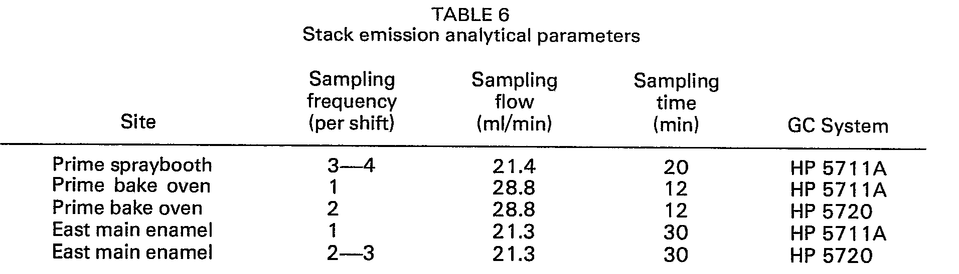


Claims (12)
Applications Claiming Priority (3)
| Application Number | Priority Date | Filing Date | Title |
|---|---|---|---|
| US2336079A | 1979-03-23 | 1979-03-23 | |
| US23360 | 1979-03-23 | ||
| AU59426/80A AU534306B2 (en) | 1979-03-23 | 1980-06-19 | Process for coating in a spray booth |
Publications (3)
| Publication Number | Publication Date |
|---|---|
| EP0026781A1 EP0026781A1 (en) | 1981-04-15 |
| EP0026781A4 EP0026781A4 (en) | 1981-08-31 |
| EP0026781B1 true EP0026781B1 (en) | 1984-08-15 |
Family
ID=25632372
Family Applications (1)
| Application Number | Title | Priority Date | Filing Date |
|---|---|---|---|
| EP80900751A Expired EP0026781B1 (en) | 1979-03-23 | 1980-10-08 | Method for coating a workpiece |
Country Status (5)
| Country | Link |
|---|---|
| EP (1) | EP0026781B1 (en) |
| JP (1) | JPS56500326A (en) |
| AU (1) | AU534306B2 (en) |
| BR (1) | BR8007658A (en) |
| WO (1) | WO1980001992A1 (en) |
Families Citing this family (1)
| Publication number | Priority date | Publication date | Assignee | Title |
|---|---|---|---|---|
| CN115634797B (en) * | 2022-11-02 | 2023-07-07 | 中国电器科学研究院股份有限公司 | A human-machine hybrid painting system and its application method |
Family Cites Families (8)
| Publication number | Priority date | Publication date | Assignee | Title |
|---|---|---|---|---|
| US2385077A (en) * | 1940-03-06 | 1945-09-18 | Binks Mfg Co | Spray booth |
| US2337983A (en) * | 1941-05-13 | 1943-12-28 | Ernest F Fisher | Spray booth |
| GB1075134A (en) * | 1964-04-27 | 1967-07-12 | Deccospray Ltd | Method and apparatus for reclaiming airborne particles from an air stream |
| US4042539A (en) * | 1973-04-12 | 1977-08-16 | E. I. Du Pont De Nemours And Company | Primer-surfacer composition of an acrylic polymer, a polyester resin and an organic dispersant |
| SE389035B (en) * | 1973-09-10 | 1976-10-25 | Greiff Svenska Maskin Ab | PROCEDURE AND DEVICE FOR AIR TRAINING FOR FERRY SPRAY PAINTING |
| DE2531748A1 (en) * | 1975-07-16 | 1977-02-03 | Buderus Eisenwerk | Densifying paint sludge in wet spray booths - by settling out, centrifuging, dumping solid matter and recycling water |
| US4042734A (en) * | 1975-12-02 | 1977-08-16 | The Gyromat Corporation | Method for spray coating |
| DE2635177C2 (en) * | 1976-08-05 | 1984-01-05 | Basf Ag, 6700 Ludwigshafen | Low-solvent stoving enamels |
-
1980
- 1980-03-21 JP JP50091880A patent/JPS56500326A/ja active Pending
- 1980-03-21 BR BR8007658A patent/BR8007658A/en unknown
- 1980-03-21 WO PCT/US1980/000432 patent/WO1980001992A1/en not_active Ceased
- 1980-06-19 AU AU59426/80A patent/AU534306B2/en not_active Ceased
- 1980-10-08 EP EP80900751A patent/EP0026781B1/en not_active Expired
Also Published As
| Publication number | Publication date |
|---|---|
| JPS56500326A (en) | 1981-03-19 |
| AU5942680A (en) | 1981-12-24 |
| EP0026781A4 (en) | 1981-08-31 |
| BR8007658A (en) | 1981-03-31 |
| WO1980001992A1 (en) | 1980-10-02 |
| AU534306B2 (en) | 1984-01-19 |
| EP0026781A1 (en) | 1981-04-15 |
Similar Documents
| Publication | Publication Date | Title |
|---|---|---|
| Hildemann et al. | A dilution stack sampler for collection of organic aerosol emissions: design, characterization and field tests | |
| Rogaski et al. | Reactive uptake and hydration experiments on amorphous carbon treated with NO2, SO2, O3, HNO3, and H2SO4 | |
| Norbäck et al. | Occupational exposure to volatile organic compounds (VOCs), and other air pollutants from the indoor application of water-based paints | |
| EP0457958B1 (en) | Spray booth for applying coatings to a substrate and control device therefore | |
| CN209117529U (en) | A kind of VOCs on-line monitoring system | |
| US5922130A (en) | Spray booth for applying coatings to substrate | |
| Wilkins | Volatile organic compounds from household waste | |
| Cheng et al. | Volatile organic compounds emission from Chinese wood furniture coating industry: Activity-based emission factor, speciation profiles, and provincial emission inventory | |
| EP0025066B1 (en) | Process for coating a workpiece | |
| Ke et al. | Volatile organic compounds concentration profiles and control strategy in container manufacturing industry: Case studies in China | |
| WO1980001992A1 (en) | Coating method with emissions abatement i | |
| CA1158106A (en) | Coating method with emissions abatement ii | |
| CA1159319A (en) | Coating with emissions abatement i | |
| Jankowski et al. | The applicability of proton transfer reaction-mass spectrometry (PTR-MS) for determination of isocyanic acid (ICA) in work room atmospheres | |
| You et al. | Emission factors and source profiles of volatile organic compounds in container manufacturing industry | |
| Mihele et al. | Particle formation and gas/particle partition measurements of the products of the naphthalene-OH radical reaction in a smog chamber | |
| Lu et al. | Analysis on the improvement of formaldehyde hazards in a spray painting position in automobile manufacturing | |
| Cohen et al. | Measurement of air concentrations of volatile aerosols in paint spray applications | |
| CN203556341U (en) | Paint mixing device | |
| Ayer et al. | Volatile Organic Compound and Particulate Emission Studies of AF (Air Force) Paint Booth Facilities. Phase 1. | |
| CN113474480A (en) | Method for the rust-forming of zinc surfaces and system therefor | |
| CN118376702A (en) | A method for continuously detecting VOCs release rate in automobile painting waste | |
| Kronholm et al. | Aerosol ionic redistribution: the calcium-phosphorus solute vaporization effect revisited | |
| LaPuma et al. | Chromate content versus particle size for aircraft paints | |
| SU866830A1 (en) | Painting booth |
Legal Events
| Date | Code | Title | Description |
|---|---|---|---|
| PUAI | Public reference made under article 153(3) epc to a published international application that has entered the european phase |
Free format text: ORIGINAL CODE: 0009012 |
|
| AK | Designated contracting states |
Designated state(s): DE FR GB SE |
|
| 17P | Request for examination filed |
Effective date: 19810316 |
|
| GRAA | (expected) grant |
Free format text: ORIGINAL CODE: 0009210 |
|
| AK | Designated contracting states |
Designated state(s): DE FR GB SE |
|
| REF | Corresponds to: |
Ref document number: 3068931 Country of ref document: DE Date of ref document: 19840920 |
|
| ET | Fr: translation filed | ||
| PLBE | No opposition filed within time limit |
Free format text: ORIGINAL CODE: 0009261 |
|
| STAA | Information on the status of an ep patent application or granted ep patent |
Free format text: STATUS: NO OPPOSITION FILED WITHIN TIME LIMIT |
|
| 26N | No opposition filed | ||
| PG25 | Lapsed in a contracting state [announced via postgrant information from national office to epo] |
Ref country code: DE Effective date: 19851203 |
|
| REG | Reference to a national code |
Ref country code: GB Ref legal event code: 746 |
|
| PG25 | Lapsed in a contracting state [announced via postgrant information from national office to epo] |
Ref country code: SE Effective date: 19870322 |
|
| REG | Reference to a national code |
Ref country code: FR Ref legal event code: DL |
|
| REG | Reference to a national code |
Ref country code: FR Ref legal event code: TP |
|
| REG | Reference to a national code |
Ref country code: GB Ref legal event code: 732 |
|
| REG | Reference to a national code |
Ref country code: FR Ref legal event code: TP |
|
| PGFP | Annual fee paid to national office [announced via postgrant information from national office to epo] |
Ref country code: GB Payment date: 19900228 Year of fee payment: 11 |
|
| PGFP | Annual fee paid to national office [announced via postgrant information from national office to epo] |
Ref country code: FR Payment date: 19910319 Year of fee payment: 12 |
|
| PG25 | Lapsed in a contracting state [announced via postgrant information from national office to epo] |
Ref country code: GB Effective date: 19910321 |
|
| GBPC | Gb: european patent ceased through non-payment of renewal fee | ||
| PG25 | Lapsed in a contracting state [announced via postgrant information from national office to epo] |
Ref country code: FR Effective date: 19921130 |
|
| REG | Reference to a national code |
Ref country code: FR Ref legal event code: ST |
|
| EUG | Se: european patent has lapsed |
Ref document number: 80900751.1 Effective date: 19880216 |