EP0023833B1 - A method of making a photographic exposure from a television picture - Google Patents
A method of making a photographic exposure from a television picture Download PDFInfo
- Publication number
- EP0023833B1 EP0023833B1 EP80302650A EP80302650A EP0023833B1 EP 0023833 B1 EP0023833 B1 EP 0023833B1 EP 80302650 A EP80302650 A EP 80302650A EP 80302650 A EP80302650 A EP 80302650A EP 0023833 B1 EP0023833 B1 EP 0023833B1
- Authority
- EP
- European Patent Office
- Prior art keywords
- inside opening
- opening
- rotary plates
- optics
- picture
- Prior art date
- Legal status (The legal status is an assumption and is not a legal conclusion. Google has not performed a legal analysis and makes no representation as to the accuracy of the status listed.)
- Expired
Links
- 238000004519 manufacturing process Methods 0.000 title claims description 4
- 238000000034 method Methods 0.000 claims description 10
- 230000003287 optical effect Effects 0.000 claims description 9
- 238000005286 illumination Methods 0.000 description 14
- 230000004907 flux Effects 0.000 description 7
- 238000010894 electron beam technology Methods 0.000 description 6
- 238000010276 construction Methods 0.000 description 4
- 238000010586 diagram Methods 0.000 description 3
- 238000006073 displacement reaction Methods 0.000 description 3
- 230000002349 favourable effect Effects 0.000 description 2
- OAICVXFJPJFONN-UHFFFAOYSA-N Phosphorus Chemical compound [P] OAICVXFJPJFONN-UHFFFAOYSA-N 0.000 description 1
- 230000002411 adverse Effects 0.000 description 1
- 230000002301 combined effect Effects 0.000 description 1
- 230000000295 complement effect Effects 0.000 description 1
- 230000007423 decrease Effects 0.000 description 1
- 230000003247 decreasing effect Effects 0.000 description 1
- 230000001419 dependent effect Effects 0.000 description 1
- 238000011156 evaluation Methods 0.000 description 1
- 230000035515 penetration Effects 0.000 description 1
- 238000003860 storage Methods 0.000 description 1
- 230000007723 transport mechanism Effects 0.000 description 1
Images
Classifications
-
- G—PHYSICS
- G03—PHOTOGRAPHY; CINEMATOGRAPHY; ANALOGOUS TECHNIQUES USING WAVES OTHER THAN OPTICAL WAVES; ELECTROGRAPHY; HOLOGRAPHY
- G03B—APPARATUS OR ARRANGEMENTS FOR TAKING PHOTOGRAPHS OR FOR PROJECTING OR VIEWING THEM; APPARATUS OR ARRANGEMENTS EMPLOYING ANALOGOUS TECHNIQUES USING WAVES OTHER THAN OPTICAL WAVES; ACCESSORIES THEREFOR
- G03B9/00—Exposure-making shutters; Diaphragms
- G03B9/08—Shutters
- G03B9/10—Blade or disc rotating or pivoting about axis normal to its plane
-
- A—HUMAN NECESSITIES
- A61—MEDICAL OR VETERINARY SCIENCE; HYGIENE
- A61B—DIAGNOSIS; SURGERY; IDENTIFICATION
- A61B6/00—Apparatus or devices for radiation diagnosis; Apparatus or devices for radiation diagnosis combined with radiation therapy equipment
-
- G—PHYSICS
- G03—PHOTOGRAPHY; CINEMATOGRAPHY; ANALOGOUS TECHNIQUES USING WAVES OTHER THAN OPTICAL WAVES; ELECTROGRAPHY; HOLOGRAPHY
- G03B—APPARATUS OR ARRANGEMENTS FOR TAKING PHOTOGRAPHS OR FOR PROJECTING OR VIEWING THEM; APPARATUS OR ARRANGEMENTS EMPLOYING ANALOGOUS TECHNIQUES USING WAVES OTHER THAN OPTICAL WAVES; ACCESSORIES THEREFOR
- G03B42/00—Obtaining records using waves other than optical waves; Visualisation of such records by using optical means
- G03B42/02—Obtaining records using waves other than optical waves; Visualisation of such records by using optical means using X-rays
Definitions
- the invention relates to a method of making a photographic exposure from a television picture, and as such it is particularly useful for taking X-ray photographs from a monitor screen.
- the manner and characteristics of the opening and closure of the optics carried out by a shutter assembly has a significant role.
- the opening and closure characteristics of the optics have a particularly decisive role when exposures are to be taken from a television screen.
- the picture on the television screen is displayed by means of an electron beam deflected according to a standard raster. Thus, the complete picture information is never available in any moment on the screen.
- the opening and closure process only a part of the light intensity of the screen will fall on the light-sensitive film, and the blackening of the corresponding film areas will be different to the blackening of the areas exposed when the optics are completely open.
- the duration of an exposure cannot last more than about the duration of a complete television picture, which is 40 msec when the mains frequency is 50 Hz.
- the opening condition of the optics should last exactly the duration of a picture, because in areas where the film receives picture information coming from more than one picture, the contrast will change.
- the characteristic of the opening of the optics is also important.
- the application of conventional, linearly moving slit shutters is not allowed because this would cause the opening of the optics to occur unevenly (corresponding to the linearly moving shutter).
- the evenness of the characteristics of conventional segmented laminar shutters, which close and open the optics annularly may be adequate.
- the opening and closure periods cannot be adjusted to the same values and the characteristic varies during use. In many constructions the opening and closure periods are too long compared to the fully open period of the optics. Attention is drawn, however, to US-A-2027520 and 2384639 both of which disclosure shutters comprising a plurality of rotatable plates which co-operate to open and close an exposure aperture.
- the task of taking precise exposures is further complicated by the fact that the illuminated condition of the television screen occurs not only in the areas where the electron beam momentarily falls, but also in the areas where the electron beam has recently fallen, the light intensity of the previously illuminated areas is maintained for a while, decreasing according to the illumination characteristics of the phosphor layer on the screen. In order to achieve precise photography it is necessary that the evenness of the contrast should be maintained in spite of the memory behaviour of the screen.
- the illumination of the film should be determined by the picture information only, because inhomogenities of the illumination arising from an imperfect method of photographic exposure might adversely affect the task of picture evaluation by the X-ray specialist.
- DE-A-1200675 describes the use of a rotary shutter for the cinematographic recording of a sequence of television pictures.
- the main problem to be solved by DE-A-1200675 is the synchronisation of the shutter and the television pictures as to frequency and phase, whereas the present invention is concerned with making a single instantaneous photograph from a sequence of television pictures.
- a photographic device which comprises an optics defining an inside opening, the optics comprising a set of lenses at its object side and a further set of lenses at its image side, and a shutter assembly arranged between said sets of lenses, said shutter assembly comprising at least two rotary plates adapted for rotary movements with identical speed around respective axes extending parallel to the optical axis of said optics and radially offset therefrom by a distance at least equal to the radius of said inside opening, said respective axes being symmetrically disposed with respect to said optical axis said rotary plates being arranged to completely cover said inside opening and define respective openings having a radial width at least equal to the size of said inside opening, said openings being moved by rotational movement of said rotary plates through positions in which said inside opening is completely uncovered by said rotary plates, the method being characterised by the steps of rotating said rotary plate with uniform angular speed and uncovering said inside opening of
- inside opening defines the cross-section of the optics through which light can pass between the two sets of lenses.
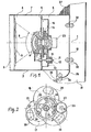
- the apparatus shown in Fig. 1 which is adapted for taking photographs from a television picture displayed on a monitor screen, has an optical axis 1 passing through the centre of the picture on a television monitor 2.
- the television monitor 2 is surrounded by a casing 7, and in the end region of the casing 7 opposite to the monitor an image plane is defined in which a film 10 is arranged.
- the interior of the casing is divided by a wall 6 into two parts, namely a part 4 which is on the objective side of the wall 6 and faces the screen 3 of the television monitor, and a part 5 on the other side of the wall 6 facing towards the image plane with the film 10.
- the casing 7 and the wall 6 mounted thereto form part of the constructional support of the apparatus.
- a multi-lens optics 8 is fixed in the wall 6 comprising lenses on both the objective and image sides of the walls.
- a shutter assembly 14 is arranged between the two sets of lenses in a chamber 13, the construction of which is explained below.
- the shutter assembly 14 is arranged around an inside opening 24 of the optics 8 (Fig. 2).
- the size of the apparatus is defined by the focal distance and the angular width 9 of the optics 8 which are designed in accordance with the required image size imaged on the film 10 in the image plane.
- the focal distance of the optics 8 can be adjusted by changing the axial position of the two sets of lenses by means of focus adjusting elements 11 and 12.
- the focus adjusting elements 11 and 12 are formed by respective threaded bolts and nuts.
- the axial position of the set of lenses in the image side is fixed, and the set of lenses in the objective side is mounted to the wall in such a way as to allow its axially guided displacement.
- the image adjustment can be carried out with fixed relative arrangement of the two sets of lenses of the optics 8 and the shutter assembly 14 located therebetween by changing the axial position of the wall 6.
- the wall 6 should be connected to the casing 7 in a way that allows its axially guided displacement.
- the structural design of the shutter assembly 14 is illustrated in Fig. 1 schematically only, but it can be seen that it comprises three rotary plates 15, 16 and 17 located in respective planes normal to the optical axis 1 in such a way that the middle rotary plate 16 can be turned between the two neighbouring outer rotary plates 15 and 17.
- Fig. 2 shows the shutter assembly 14 in a schematic illustration. Of the axes of the three rotary plates 15, 16 and 17 only the three respective fulcrums 25, 26 and 27 can be seen in Fig. 2 which are arranged at the apex points of an imaginary equilateral triangle. Respective cog-wheels 18, 19 and 20 are mounted on the three axes and engage an annular gear 21 with internal gearing. The annular gear 21 is driven by a step motor 23 through an intermediate gear 22. In Fig. 2 respective arrows show the sense of rotation of each wheel.
- Each of the rotary plates 15, 16 and 17 comprises a pair of openings 28, 29 and 30 and the radial width of each of the openings is at least equal to the diameter of the inside opening 24 of the optics 8.
- each of the openings 28, 29 and 30 will be connected through respective imaginary straight lines with the optical axis 1, then these straight lines will be at angles of 120° to one another. It can be understood that when the step motor 23 is running, the openings 28, 29 and 30 will periodically move towards and away from the optical axis 1. When the openings are adjacent the axis 1, the inside openings 24 will be uncovered, and when the openings move away from the axis the opening 24 will be covered. Since in the exemplary embodiment each of the rotary plates 15, 16 and 17 comprises a pair of openings, in each complete revolution of the rotary plates the inside opening 24 will be twice completely uncovered and covered again.
- the front and rear ends of the openings 28, 29 and 30 are defined by circular arc sections having centres falling on an imaginary annular path of each rotary plate 15, 16 and 17 that crosses the optical axis 1. It can be appreciated that other shapes can also be used for the end sections of the openings 28, 29 and 30, provided that the sheet meets the condition that the front and rear end sections of any opening have corresponding shapes, whereby the opening and closure processes of the inside opening 24 will have identical characteristics.
- the angular width (length of the arc) of the openings 28, 29 and 30 defined between their respective end sections determines substantially the length of the open period of the shutter assembly 14, which open period is also dependent on the speed of the step motor 23 that defines directly the speed of revolution of the rotary plates 15, 16 and 17.
- the film 10 is moved from a storage region 37 through pairs of rollers 32, 33 and 34 to a collecting station 36.
- a guiding arc plate 35 is used for diverting the films into the required direction.
- the film transport mechanism is arranged in a chamber 31 which is inside the housing of the apparatus and it is protected from the penetration of light from outside.
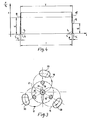
- Fig. 3 is a kinematic illustration of the operation of the shutter assembly.
- the openings 28, 29 and 30 of the three rotary plates 15, 16 and 17 are shown together with the driving cog-wheels 18, 19 and 20 for the rotary plates.
- each rotary plate is supposed to comprise a single opening only.
- the operation of the shutter assembly is as follows. It is supposed that at the beginning of an exposure all the three openings are in the starting position shown in Fig. 3, and the inside opening 24 is closed by the rotary plates 15, 16 and 17. Some time after the assembly starts to move, the annular gear 21 rotates with uniform angular speed, whereby the openings 28, 29 and 30 will approach towards the inside opening 24 along respective circular paths as shown by the arrows in Fig. 3. When the openings 28, 29 and 30 travelling from three directions reach the inside opening 24, the light path through the inside opening 24 will be quickly uncovered. The light can pass through the inside opening 24 as long as the openings 28, 29 and 30 enable it to.
- Fig. 4 shows the time diagram of the relative light flux F/F o passing through the inside opening 24.
- the illumination will be smaller than between the moments t 1 and t 2 when full illumination is ensured. This means that a band on the picture beginning at the starting position of the electron beam at the moment to and having a predetermined width corresponding to the length of the opening section A will have a gradually increased illumination.
- the required missing illumination should be added in the closing section B.
- the relative light flux has a value F 1 .
- the picture information of the next picture is used. This information, however, due to the very small time difference between two subsequent pictures can be considered to be substantially identical with the information of the previous picture.
- the exact adjustment of the period time T can be carried out by finely changing the speed of the rotary plates 15, 16 and 17.
- the shutter assembly shown in Figs. 1, 2 and 3 comprises three rotary plates.
- the number of rotary plates is increased, more favourable opening and closing characteristics can be attained.
- the increased number of the rotary plates makes the constructional design more complicated, experience has shown that the use of more than three rotary plates does not provide substantially better results.
- the number of the rotary plates can be reduced to two, but in that case the opening and closing characteristics will be quite noticeably less favourable than in the case of using three rotary plates.
Landscapes
- Health & Medical Sciences (AREA)
- Life Sciences & Earth Sciences (AREA)
- Physics & Mathematics (AREA)
- Medical Informatics (AREA)
- General Physics & Mathematics (AREA)
- Engineering & Computer Science (AREA)
- Biomedical Technology (AREA)
- Surgery (AREA)
- Nuclear Medicine, Radiotherapy & Molecular Imaging (AREA)
- Optics & Photonics (AREA)
- Pathology (AREA)
- Radiology & Medical Imaging (AREA)
- Biophysics (AREA)
- Heart & Thoracic Surgery (AREA)
- Molecular Biology (AREA)
- High Energy & Nuclear Physics (AREA)
- Animal Behavior & Ethology (AREA)
- General Health & Medical Sciences (AREA)
- Public Health (AREA)
- Veterinary Medicine (AREA)
- Apparatus For Radiation Diagnosis (AREA)
- Shutters For Cameras (AREA)
- Radiography Using Non-Light Waves (AREA)
- Projection-Type Copiers In General (AREA)
Description
- The invention relates to a method of making a photographic exposure from a television picture, and as such it is particularly useful for taking X-ray photographs from a monitor screen.
- In professional photographing techniques, the manner and characteristics of the opening and closure of the optics carried out by a shutter assembly has a significant role. The more perfect the shutter construction is, the shorter the opening and closure periods are compared to the fully open condition. The opening and closure characteristics of the optics have a particularly decisive role when exposures are to be taken from a television screen. As it is known, the picture on the television screen is displayed by means of an electron beam deflected according to a standard raster. Thus, the complete picture information is never available in any moment on the screen.
- During the opening and closure process only a part of the light intensity of the screen will fall on the light-sensitive film, and the blackening of the corresponding film areas will be different to the blackening of the areas exposed when the optics are completely open. When X-ray photographs are to be taken from a monitor screen, because of the possibility of an accidental movement of the patient or of the displacement of an examined phenomenon within the body of the patient, the duration of an exposure cannot last more than about the duration of a complete television picture, which is 40 msec when the mains frequency is 50 Hz. In order that the light sensitive film should receive picture information coming from one and the same picture, the opening condition of the optics should last exactly the duration of a picture, because in areas where the film receives picture information coming from more than one picture, the contrast will change.
- With the above requirements the characteristic of the opening of the optics is also important. The application of conventional, linearly moving slit shutters is not allowed because this would cause the opening of the optics to occur unevenly (corresponding to the linearly moving shutter). The evenness of the characteristics of conventional segmented laminar shutters, which close and open the optics annularly may be adequate. However, using such shutters the opening and closure periods cannot be adjusted to the same values and the characteristic varies during use. In many constructions the opening and closure periods are too long compared to the fully open period of the optics. Attention is drawn, however, to US-A-2027520 and 2384639 both of which disclosure shutters comprising a plurality of rotatable plates which co-operate to open and close an exposure aperture.
- The task of taking precise exposures is further complicated by the fact that the illuminated condition of the television screen occurs not only in the areas where the electron beam momentarily falls, but also in the areas where the electron beam has recently fallen, the light intensity of the previously illuminated areas is maintained for a while, decreasing according to the illumination characteristics of the phosphor layer on the screen. In order to achieve precise photography it is necessary that the evenness of the contrast should be maintained in spite of the memory behaviour of the screen.
- In the case of X-ray photography technique the illumination of the film should be determined by the picture information only, because inhomogenities of the illumination arising from an imperfect method of photographic exposure might adversely affect the task of picture evaluation by the X-ray specialist.
- DE-A-1200675 describes the use of a rotary shutter for the cinematographic recording of a sequence of television pictures. However, the main problem to be solved by DE-A-1200675 is the synchronisation of the shutter and the television pictures as to frequency and phase, whereas the present invention is concerned with making a single instantaneous photograph from a sequence of television pictures.
- According to the invention there is provided a method of making a photographic exposure from a television picture, wherein a photographic device is used therefor which comprises an optics defining an inside opening, the optics comprising a set of lenses at its object side and a further set of lenses at its image side, and a shutter assembly arranged between said sets of lenses, said shutter assembly comprising at least two rotary plates adapted for rotary movements with identical speed around respective axes extending parallel to the optical axis of said optics and radially offset therefrom by a distance at least equal to the radius of said inside opening, said respective axes being symmetrically disposed with respect to said optical axis said rotary plates being arranged to completely cover said inside opening and define respective openings having a radial width at least equal to the size of said inside opening, said openings being moved by rotational movement of said rotary plates through positions in which said inside opening is completely uncovered by said rotary plates, the method being characterised by the steps of rotating said rotary plate with uniform angular speed and uncovering said inside opening of said optics for a period defined between a starting moment and a finishing moment, said uncovering period comprising an opening section with partly open inside opening, an open period with completely open inside opening and a closing section with partly open inside opening, and adjusting the duration of said uncovering period to be the combined length of a full picture duration of the television picture and of the duration of either said opening section or said closing section.
- The term "inside opening" defines the cross-section of the optics through which light can pass between the two sets of lenses.
- When an exposure is taken according to this method, during the opening and closing sections identical picture details will be illuminated in such a way that the combined effect of the double illumination will be identical to the illumination that occurs with completely open optics.
- Using the method of the invention and with an opening period of 40 msec (that corresponds to a picture period) the duration of the opening and closing sections was adjusted to a preferable value of 0.8 msec which value always remained the same in each exposure. The invention will now be described in connection with preferred forms of shutter assembly for use therein.
- In the drawings:
- Fig. 1 shows in schematical elevational sectional view a photographing device equipped with a preferred shutter assembly;
- Fig. 2 shows the side view of the shutter assembly shown in Fig. 1;
- Fig. 3 is a simplified schematic illustration of the operation of the shutter assembly; and
- Fig. 4 is a time diagram of the relative light-flux passing through the inside opening of the optics.
- The apparatus shown in Fig. 1, which is adapted for taking photographs from a television picture displayed on a monitor screen, has an
optical axis 1 passing through the centre of the picture on a television monitor 2. The television monitor 2 is surrounded by a casing 7, and in the end region of the casing 7 opposite to the monitor an image plane is defined in which afilm 10 is arranged. The interior of the casing is divided by awall 6 into two parts, namely a part 4 which is on the objective side of thewall 6 and faces the screen 3 of the television monitor, and a part 5 on the other side of thewall 6 facing towards the image plane with thefilm 10. The casing 7 and thewall 6 mounted thereto form part of the constructional support of the apparatus. A multi-lens optics 8 is fixed in thewall 6 comprising lenses on both the objective and image sides of the walls. Ashutter assembly 14 is arranged between the two sets of lenses in achamber 13, the construction of which is explained below. Theshutter assembly 14 is arranged around an inside opening 24 of the optics 8 (Fig. 2). - The size of the apparatus is defined by the focal distance and the angular width 9 of the optics 8 which are designed in accordance with the required image size imaged on the
film 10 in the image plane. The focal distance of the optics 8 can be adjusted by changing the axial position of the two sets of lenses by means offocus adjusting elements 11 and 12. In the exemplary embodiment shown in Fig. 1 thefocus adjusting elements 11 and 12 are formed by respective threaded bolts and nuts. The axial position of the set of lenses in the image side is fixed, and the set of lenses in the objective side is mounted to the wall in such a way as to allow its axially guided displacement. By changing the focal distance the picture on the screen 3 can be adjusted to be sharply imaged in the image plane. - In an alternative embodiment (not shown in the drawing) the image adjustment can be carried out with fixed relative arrangement of the two sets of lenses of the optics 8 and the
shutter assembly 14 located therebetween by changing the axial position of thewall 6. In that case thewall 6 should be connected to the casing 7 in a way that allows its axially guided displacement. - During the photographic exposure of the viewing screen 3 exactly one and only one complete television picture should mark a trace in the
film 10. The design of theshutter assembly 14 should ensure this by providing specific opening and closure characteristics. - The structural design of the
shutter assembly 14 is illustrated in Fig. 1 schematically only, but it can be seen that it comprises threerotary plates optical axis 1 in such a way that the middlerotary plate 16 can be turned between the two neighbouring outerrotary plates - Fig. 2 shows the
shutter assembly 14 in a schematic illustration. Of the axes of the threerotary plates respective fulcrums wheels annular gear 21 with internal gearing. Theannular gear 21 is driven by astep motor 23 through anintermediate gear 22. In Fig. 2 respective arrows show the sense of rotation of each wheel. - Each of the
rotary plates openings - If any arbitrarily selected point of each of the
openings optical axis 1, then these straight lines will be at angles of 120° to one another. It can be understood that when thestep motor 23 is running, theopenings optical axis 1. When the openings are adjacent theaxis 1, theinside openings 24 will be uncovered, and when the openings move away from the axis theopening 24 will be covered. Since in the exemplary embodiment each of therotary plates - In the exemplary embodiment the front and rear ends of the
openings rotary plate optical axis 1. It can be appreciated that other shapes can also be used for the end sections of theopenings inside opening 24 will have identical characteristics. - The angular width (length of the arc) of the
openings shutter assembly 14, which open period is also dependent on the speed of thestep motor 23 that defines directly the speed of revolution of therotary plates - Referring now again to Fig. 1 the movement of the
film 10 arranged in the image plane will be described. Thefilm 10 is moved from astorage region 37 through pairs ofrollers collecting station 36. A guidingarc plate 35 is used for diverting the films into the required direction. The film transport mechanism is arranged in achamber 31 which is inside the housing of the apparatus and it is protected from the penetration of light from outside. - Fig. 3 is a kinematic illustration of the operation of the shutter assembly. In this figure only the
openings rotary plates wheels - The operation of the shutter assembly is as follows. It is supposed that at the beginning of an exposure all the three openings are in the starting position shown in Fig. 3, and the
inside opening 24 is closed by therotary plates annular gear 21 rotates with uniform angular speed, whereby theopenings inside opening 24 along respective circular paths as shown by the arrows in Fig. 3. When theopenings inside opening 24, the light path through theinside opening 24 will be quickly uncovered. The light can pass through theinside opening 24 as long as theopenings rotary plates openings inside opening 24 with the same speed and on corresponding paths as they have approached it. The rotation of therotary plates - Fig. 4 shows the time diagram of the relative light flux F/Fo passing through the
inside opening 24. At the moment to the front edges of theopenings inside opening 24 during their approach thereto. Thereafter the light flux through the inside opening rapidly increases according to a characteristic corresponding to the shape of theopenings inside opening 24 will be free and the values of the relative light flux F/Fo will be unity. This condition lasts until the moment t2 when the rear edges of theopenings inside opening 24. From now on the openings move away from theinside opening 24 and the relative light-flux rapidly decreases. At the moment t3 the rotary plates completely close theinside opening 24. - In the above described construction the light flux varies in the opening section A and the closing section B according to identical characteristics.
- In connection with Fig. 4 the conditions required for the photography of a complete television picture will be examined, if the exposure is to provide a uniform and undistorted illumination. It will be supposed that the picture frequency is 25 Hz and the corresponding duration T of each picture is T=40 msec. It will also be supposed that between the moments to and t, just T=40 msec time has elapsed. This means that the electron beam that forms the picture on the screen falls on the same point of the screen 3 at the moments to and t2.
- It can be seen that in the opening section A, which lasts 0.8 msec, the illumination will be smaller than between the moments t1 and t2 when full illumination is ensured. This means that a band on the picture beginning at the starting position of the electron beam at the moment to and having a predetermined width corresponding to the length of the opening section A will have a gradually increased illumination. In order to ensure a uniform illumination for the picture, the required missing illumination should be added in the closing section B. At point P, that falls about the middle of the opening section A, the relative light flux has a value F1. A complete period T following the moment tx of the point P,, i.e. at the moment ty=tx+T the electron beam illuminates the same part of the screen as at point P,. In the diagram of Fig. 4 the curve is at point P at the moment tY. As was explained, the points P, and P are associated with one and the same location on the screen. It can be seen in Fig. 4 that at the moment ty the relative light flux has a value F2. Owing to the fact that the opening and closing sections A and B have identical characteristics with inverted sense, it can be understood that the sum of the relative light fluxes F1 and F2 corresponding to the points P, and P2 that define the same location on the screen will be unity, i.e. F,+FZ=1. Since the durations of the opening and closing sections A and B are identical, it should be clear that every location on the screen which was associated in the opening section A with an illumination smaller than unity will be associated in the closing section B with the complementary illumination required to reach the value of units, whereby the illumination of the complete picture will be uniformly unity, if the above conditions are met.
- In the closing section B the picture information of the next picture is used. This information, however, due to the very small time difference between two subsequent pictures can be considered to be substantially identical with the information of the previous picture. The exact adjustment of the period time T can be carried out by finely changing the speed of the
rotary plates - The shutter assembly shown in Figs. 1, 2 and 3 comprises three rotary plates. However, if the number of rotary plates is increased, more favourable opening and closing characteristics can be attained. The increased number of the rotary plates, however, makes the constructional design more complicated, experience has shown that the use of more than three rotary plates does not provide substantially better results. In an extreme case the number of the rotary plates can be reduced to two, but in that case the opening and closing characteristics will be quite noticeably less favourable than in the case of using three rotary plates.
Claims (2)
Applications Claiming Priority (2)
| Application Number | Priority Date | Filing Date | Title |
|---|---|---|---|
| HUME002289 | 1979-08-07 | ||
| HU79ME2289A HU179247B (en) | 1979-08-07 | 1979-08-07 | Apparatus for indentifying patients in x-ray systems with image amplifier |
Publications (2)
| Publication Number | Publication Date |
|---|---|
| EP0023833A1 EP0023833A1 (en) | 1981-02-11 |
| EP0023833B1 true EP0023833B1 (en) | 1983-05-11 |
Family
ID=10999538
Family Applications (1)
| Application Number | Title | Priority Date | Filing Date |
|---|---|---|---|
| EP80302650A Expired EP0023833B1 (en) | 1979-08-07 | 1980-08-04 | A method of making a photographic exposure from a television picture |
Country Status (10)
| Country | Link |
|---|---|
| US (2) | US4358855A (en) |
| EP (1) | EP0023833B1 (en) |
| JP (1) | JPS5627118A (en) |
| CA (2) | CA1158910A (en) |
| DD (1) | DD153577A1 (en) |
| DE (2) | DE3029088A1 (en) |
| FR (1) | FR2463429A1 (en) |
| HU (1) | HU179247B (en) |
| NL (1) | NL8004354A (en) |
| SE (1) | SE437467B (en) |
Families Citing this family (9)
| Publication number | Priority date | Publication date | Assignee | Title |
|---|---|---|---|---|
| DE3041361A1 (en) * | 1980-11-03 | 1982-06-09 | Siemens AG, 1000 Berlin und 8000 München | X-RAY DIAGNOSTIC SYSTEM WITH SEVERAL X-RAY GENERAL WORKPLACES |
| JPH0447695Y2 (en) * | 1985-06-18 | 1992-11-11 | ||
| JPS61290428A (en) * | 1985-06-18 | 1986-12-20 | Yamaguchi Shinema:Kk | Rotary disc type shutter for television camera |
| US4812911A (en) * | 1986-01-28 | 1989-03-14 | Canon Kabushiki Kaisha | Adapter with built-in shutter |
| JPH0725783Y2 (en) * | 1989-04-07 | 1995-06-07 | 株式会社コパル | Camera shutter support structure |
| US5127394A (en) * | 1989-06-26 | 1992-07-07 | Tilane Corporation | Fluoroscopy switching device |
| US4993404A (en) * | 1989-06-26 | 1991-02-19 | Lane Timothy G | Fluoroscopy switching device |
| US6368269B1 (en) | 1993-05-20 | 2002-04-09 | Tilane Corporation | Apparatus for concurrent actuation of multiple foot pedal operated switches |
| CN111109169B (en) * | 2020-01-21 | 2021-12-28 | 大连海洋大学 | Automatic shellfish seeding device |
Family Cites Families (14)
| Publication number | Priority date | Publication date | Assignee | Title |
|---|---|---|---|---|
| DE35100C (en) * | C. LÜTken in Kopenhagen, Dänemark | Momentary lock | ||
| US689982A (en) * | 1901-02-21 | 1901-12-31 | William Howard Morgan | Photographic shutter. |
| US778334A (en) * | 1904-03-15 | 1904-12-27 | John Asa Ricketts | Camera-shutter. |
| US1716512A (en) * | 1926-02-08 | 1929-06-11 | Zeiss Carl Fa | Photographic shutter |
| US1883998A (en) * | 1931-03-12 | 1932-10-25 | Agfa Ansco Corp | Camera shutter |
| US2027520A (en) * | 1934-12-20 | 1936-01-14 | Diebel Israel | Shutter mechanism for motion picture projectors |
| US2350355A (en) * | 1941-05-19 | 1944-06-06 | Mitchell Camera Corp | Shutter mechanism |
| US2384639A (en) * | 1942-09-23 | 1945-09-11 | Eastman Kodak Co | High-speed shutter |
| US2383381A (en) * | 1942-10-28 | 1945-08-21 | Hammond Laurens | Camera shutter |
| DE1200675B (en) * | 1962-11-05 | 1965-09-09 | Optische Ind De Oude Delft Nv | Device for the cinematographic recording of the screen images of television picture tubes |
| DE2101050B2 (en) * | 1971-01-11 | 1973-09-20 | Siemens Ag, 1000 Berlin U. 8000 Muenchen | X-ray television device |
| US3924064A (en) * | 1973-03-27 | 1975-12-02 | Hitachi Medical Corp | X-ray inspection equipment for baggage |
| US4076984A (en) * | 1976-06-23 | 1978-02-28 | Jury Vasilievich Gromov | Introscope |
| HU177686B (en) * | 1978-04-11 | 1981-12-28 | Medicor Muevek | Shifting construction for sheet film,in particular,to diagnostical x-ray apparatuses |
-
1979
- 1979-08-07 HU HU79ME2289A patent/HU179247B/en unknown
-
1980
- 1980-07-18 SE SE8005270A patent/SE437467B/en not_active IP Right Cessation
- 1980-07-22 FR FR8016092A patent/FR2463429A1/en active Granted
- 1980-07-30 NL NL8004354A patent/NL8004354A/en not_active Application Discontinuation
- 1980-07-31 DE DE19803029088 patent/DE3029088A1/en not_active Withdrawn
- 1980-08-04 EP EP80302650A patent/EP0023833B1/en not_active Expired
- 1980-08-04 DE DE8080302650T patent/DE3063132D1/en not_active Expired
- 1980-08-04 DD DD80223096A patent/DD153577A1/en unknown
- 1980-08-06 US US06/175,436 patent/US4358855A/en not_active Expired - Lifetime
- 1980-08-06 US US06/175,437 patent/US4306796A/en not_active Expired - Lifetime
- 1980-08-06 JP JP10724380A patent/JPS5627118A/en active Pending
- 1980-08-07 CA CA000357767A patent/CA1158910A/en not_active Expired
- 1980-08-07 CA CA000357768A patent/CA1145994A/en not_active Expired
Also Published As
| Publication number | Publication date |
|---|---|
| NL8004354A (en) | 1981-02-10 |
| DE3029088A1 (en) | 1982-03-04 |
| JPS5627118A (en) | 1981-03-16 |
| SE437467B (en) | 1985-03-04 |
| SE8005270L (en) | 1981-02-08 |
| HU179247B (en) | 1982-09-28 |
| CA1145994A (en) | 1983-05-10 |
| FR2463429A1 (en) | 1981-02-20 |
| EP0023833A1 (en) | 1981-02-11 |
| DD153577A1 (en) | 1982-01-20 |
| US4306796A (en) | 1981-12-22 |
| FR2463429B1 (en) | 1984-01-20 |
| DE3063132D1 (en) | 1983-06-16 |
| US4358855A (en) | 1982-11-09 |
| CA1158910A (en) | 1983-12-20 |
Similar Documents
| Publication | Publication Date | Title |
|---|---|---|
| US3909121A (en) | Panoramic photographic methods | |
| US4306796A (en) | Shutter assembly for photographing devices with precision timing facility | |
| CA2249644A1 (en) | Method and apparatus for creating cylindrical three-dimensional picture | |
| US2068410A (en) | Photographic camera and projector apparatus | |
| US4357081A (en) | Projector for the projection of a panoramic image and camera for the manufacture of films for a projector of this kind | |
| US4145131A (en) | Compact camera and viewer apparatus | |
| US3950769A (en) | Compact camera and viewer apparatus | |
| US3191182A (en) | Apparatus for making wide angle pictures | |
| GB2066973A (en) | Panoramic camera | |
| US2349931A (en) | Panoramic camera | |
| US4291962A (en) | Lens mask for cameras and photographic method | |
| US4085328A (en) | X-ray examining device | |
| JPS5932776B2 (en) | photographic equipment | |
| US3642367A (en) | Movie viewing and still copy camera | |
| JP2769396B2 (en) | Continuous shooting camera | |
| JP2596302Y2 (en) | Shutter device for continuous shooting camera | |
| US4588275A (en) | Photographic apparatus | |
| US3363527A (en) | Apparatus for making panoramic photographs | |
| US1137320A (en) | Shutter for moving-picture machines. | |
| JPH0355950Y2 (en) | ||
| JP3179919B2 (en) | Optical path switching mechanism | |
| JP3086772B2 (en) | Shutter for continuous shooting | |
| GB905244A (en) | Cinematographic method and apparatus | |
| JP3086770B2 (en) | Shutter for continuous shooting | |
| SU34311A1 (en) | Film making machine |
Legal Events
| Date | Code | Title | Description |
|---|---|---|---|
| PUAI | Public reference made under article 153(3) epc to a published international application that has entered the european phase |
Free format text: ORIGINAL CODE: 0009012 |
|
| AK | Designated contracting states |
Designated state(s): BE DE FR GB NL SE |
|
| 17P | Request for examination filed |
Effective date: 19810228 |
|
| RBV | Designated contracting states (corrected) |
Designated state(s): BE DE FR GB NL SE |
|
| GRAA | (expected) grant |
Free format text: ORIGINAL CODE: 0009210 |
|
| AK | Designated contracting states |
Designated state(s): BE DE FR GB NL SE |
|
| REF | Corresponds to: |
Ref document number: 3063132 Country of ref document: DE Date of ref document: 19830616 |
|
| ET | Fr: translation filed | ||
| PGFP | Annual fee paid to national office [announced via postgrant information from national office to epo] |
Ref country code: FR Payment date: 19840621 Year of fee payment: 5 |
|
| PGFP | Annual fee paid to national office [announced via postgrant information from national office to epo] |
Ref country code: DE Payment date: 19840808 Year of fee payment: 5 |
|
| PGFP | Annual fee paid to national office [announced via postgrant information from national office to epo] |
Ref country code: SE Payment date: 19840930 Year of fee payment: 5 Ref country code: BE Payment date: 19840930 Year of fee payment: 5 |
|
| PLBE | No opposition filed within time limit |
Free format text: ORIGINAL CODE: 0009261 |
|
| STAA | Information on the status of an ep patent application or granted ep patent |
Free format text: STATUS: NO OPPOSITION FILED WITHIN TIME LIMIT |
|
| 26N | No opposition filed | ||
| PGFP | Annual fee paid to national office [announced via postgrant information from national office to epo] |
Ref country code: NL Payment date: 19860831 Year of fee payment: 7 |
|
| PG25 | Lapsed in a contracting state [announced via postgrant information from national office to epo] |
Ref country code: SE Effective date: 19870805 |
|
| BERE | Be: lapsed |
Owner name: MEDICOR MUVEK Effective date: 19870831 |
|
| PG25 | Lapsed in a contracting state [announced via postgrant information from national office to epo] |
Ref country code: NL Effective date: 19880301 |
|
| NLV4 | Nl: lapsed or anulled due to non-payment of the annual fee | ||
| PG25 | Lapsed in a contracting state [announced via postgrant information from national office to epo] |
Ref country code: FR Free format text: LAPSE BECAUSE OF NON-PAYMENT OF DUE FEES Effective date: 19880429 |
|
| PG25 | Lapsed in a contracting state [announced via postgrant information from national office to epo] |
Ref country code: DE Effective date: 19880503 |
|
| GBPC | Gb: european patent ceased through non-payment of renewal fee | ||
| REG | Reference to a national code |
Ref country code: FR Ref legal event code: ST |
|
| PG25 | Lapsed in a contracting state [announced via postgrant information from national office to epo] |
Ref country code: GB Free format text: LAPSE BECAUSE OF NON-PAYMENT OF DUE FEES Effective date: 19881118 |
|
| PG25 | Lapsed in a contracting state [announced via postgrant information from national office to epo] |
Ref country code: BE Effective date: 19890831 |
|
| EUG | Se: european patent has lapsed |
Ref document number: 80302650.9 Effective date: 19880711 |