EP0023677B1 - Improvements in and relating to vehicle speed control systems - Google Patents
Improvements in and relating to vehicle speed control systems Download PDFInfo
- Publication number
- EP0023677B1 EP0023677B1 EP80104368A EP80104368A EP0023677B1 EP 0023677 B1 EP0023677 B1 EP 0023677B1 EP 80104368 A EP80104368 A EP 80104368A EP 80104368 A EP80104368 A EP 80104368A EP 0023677 B1 EP0023677 B1 EP 0023677B1
- Authority
- EP
- European Patent Office
- Prior art keywords
- speed
- vehicle
- voltage
- signal
- electrical signal
- Prior art date
- Legal status (The legal status is an assumption and is not a legal conclusion. Google has not performed a legal analysis and makes no representation as to the accuracy of the status listed.)
- Expired
Links
Images


Classifications
-
- B—PERFORMING OPERATIONS; TRANSPORTING
- B60—VEHICLES IN GENERAL
- B60K—ARRANGEMENT OR MOUNTING OF PROPULSION UNITS OR OF TRANSMISSIONS IN VEHICLES; ARRANGEMENT OR MOUNTING OF PLURAL DIVERSE PRIME-MOVERS IN VEHICLES; AUXILIARY DRIVES FOR VEHICLES; INSTRUMENTATION OR DASHBOARDS FOR VEHICLES; ARRANGEMENTS IN CONNECTION WITH COOLING, AIR INTAKE, GAS EXHAUST OR FUEL SUPPLY OF PROPULSION UNITS IN VEHICLES
- B60K31/00—Vehicle fittings, acting on a single sub-unit only, for automatically controlling vehicle speed, i.e. preventing speed from exceeding an arbitrarily established velocity or maintaining speed at a particular velocity, as selected by the vehicle operator
- B60K31/02—Vehicle fittings, acting on a single sub-unit only, for automatically controlling vehicle speed, i.e. preventing speed from exceeding an arbitrarily established velocity or maintaining speed at a particular velocity, as selected by the vehicle operator including electrically actuated servomechanism
- B60K31/04—Vehicle fittings, acting on a single sub-unit only, for automatically controlling vehicle speed, i.e. preventing speed from exceeding an arbitrarily established velocity or maintaining speed at a particular velocity, as selected by the vehicle operator including electrically actuated servomechanism and means for comparing one electrical quantity, e.g. voltage, pulse, waveform, flux, or the like, with another quantity of a like kind, which comparison means is involved in the development of an electrical signal which is fed into the controlling means
- B60K31/042—Vehicle fittings, acting on a single sub-unit only, for automatically controlling vehicle speed, i.e. preventing speed from exceeding an arbitrarily established velocity or maintaining speed at a particular velocity, as selected by the vehicle operator including electrically actuated servomechanism and means for comparing one electrical quantity, e.g. voltage, pulse, waveform, flux, or the like, with another quantity of a like kind, which comparison means is involved in the development of an electrical signal which is fed into the controlling means where at least one electrical quantity is set by the vehicle operator
- B60K31/045—Vehicle fittings, acting on a single sub-unit only, for automatically controlling vehicle speed, i.e. preventing speed from exceeding an arbitrarily established velocity or maintaining speed at a particular velocity, as selected by the vehicle operator including electrically actuated servomechanism and means for comparing one electrical quantity, e.g. voltage, pulse, waveform, flux, or the like, with another quantity of a like kind, which comparison means is involved in the development of an electrical signal which is fed into the controlling means where at least one electrical quantity is set by the vehicle operator in a memory, e.g. a capacitor
-
- B—PERFORMING OPERATIONS; TRANSPORTING
- B60—VEHICLES IN GENERAL
- B60W—CONJOINT CONTROL OF VEHICLE SUB-UNITS OF DIFFERENT TYPE OR DIFFERENT FUNCTION; CONTROL SYSTEMS SPECIALLY ADAPTED FOR HYBRID VEHICLES; ROAD VEHICLE DRIVE CONTROL SYSTEMS FOR PURPOSES NOT RELATED TO THE CONTROL OF A PARTICULAR SUB-UNIT
- B60W2552/00—Input parameters relating to infrastructure
- B60W2552/15—Road slope, i.e. the inclination of a road segment in the longitudinal direction
Definitions
- the invention relates to vehicle speed control systems arranged when rendered operative to control the engine of the vehicle so as to tend to hold the vehicle to run at a desired speed.
- a vehicle speed control system is known (see U.S. Patent No. 4072206) in which the upper and lower cut-out limits are provided which automatically cut the speed control system out of operation should the vehicle speed exceed a fixed limit close to the vehicle's maximum speed or fall below a low fixed limit.
- the vehicle's speed would have to change very substantially from the desired speed before it reached on of the fixed limits, and during the whole of this time the speed control system would be trying to rectify the increasing speed error. This could well create a dangerous situation.
- a vehicle speed control system arranged when rendered operative to control the engine of the vehicle so as to tend to hold the vehicle to run at a desired speed, and including generating circuitry for generating signals representing upper and lower limits of a speed range in which the desired speed lies, comparing circuitry operative to compare the actual vehicle's speed with the said limits, and disabling means operative to disable the speed control system when the actual vehicle's speed falls outside the speed speed range, is characterised in that the upper and lower speed limits define a relatively narrow speed range and both change in value in the same direction as any change in value of the desired speed.
- the systems to be described are for automatically controlling a motor vehicle to run at a predetermined speed which is set by the driver. Once the speed has been selected and set by the driver, the system operates automatically to hold the vehicle at that speed, subject, of course, to the speed being within the capability of the vehicle having regard to the gradient and other features. In the system to be described, if the speed required becomes outside the capability of the vehicle, the system is automatically switched off, whereafter control of the vehicle speed is resumed by the driver.
- FIG. 1 shows the engine 10 of the motor vehicle driving the propellor shaft 12 through a gearbox 14, the speed of the engine being regulated by means of a throttle control 15.
- the control 15 will normally form a part of the engine carburetter and is arranged to be adjustable by the driver's throttle pedal in the usual way. In addition, however, it is connected to be adjustable by means of a throttle actuator 16.
- a line 17 carries a pulsating electrical signal whose frequency is dependent on the road speed of the vehicle.
- This signal is derived in a road speed transducer which may be of any suitable type.
- it can comprise an electromagnetic transducer sensing the rotational speed of the propeller shaft of the vehicle.
- various other means can be used for producing an electrical signal dependent on the road speed of the vehicle.
- the speed dependnet signal on line 17 is then passed to a frequency-to-voltage converter 22 which produces an output voltage Vs on a line 21 dependent on engine speed.
- the system may be arranged so that either the signal Vs is proportional to engine speed or inversely proportional to engine speed.
- the circuit 22 may take any suitable form. It may, for example, comprise a limiting amplifier and monostable circuit for converting the pulse signal on line 17 into a rectangular wave of constant amplitude and width followed by a smoothing circuit.
- the speed-dependent signal Vs is then fed to a memory 36 and is also fed directly to a filter 38.
- the memory 36 and the filter 38 produce respective outputs Vm and Vf which are both fed to an error amplifier 42.
- the latter drives a drive circuit 46 which in turn drives the throttle actuator 16.
- switch 48 When the driver wishes to bring the system into operation to control the vehicle to run at a particular speed, he accelerates the vehicle up to that speed (or decelerates it down to that speed) and momentarily closes a switch 48 when the vehicle is running at the desired speed.
- This momentary closure of switch 48 causes a control unit 50 to activate a memory 36 by mens of a line 52 and feeds into the memory 36 a signal dependent on that vehicle speed.
- This signal becomes stored in the memory 36 when the switch 48 is once more open, and is fed as the signal Vm to one input of the error amplifier 42.
- the other input of the amplifier 42 receives the signal Vf from the filter 38.
- Vf is affected by the rate of change of Vs so as to tend to change by a greater amount when Vs is changing rapidly than when Vs is changing slowly, and therefore leads on Vs when the vehicle speed is changing rapidly, in either sense.
- the two inputs to the error amplifier 42 will be equal and the throttle actuator 16 will hold the throttle control unchanged. If the vehicle tends to change speed from the desired setting, however, there will be a resultant change in engine speed and Vf will change.
- the error amplifier 42 will produce a corresponding output which will energise the drive circuit 46 in such a direction as to cause the throttle actuator 16 to adjust the position of the throttle control 15 so as to tend to bring the vehicle back to the desired speed.
- the control unit 50 checks the various operating parameters of the vehicle to determine whether the system can be brought into operation (in response to operation of the switch 48 by the driver) or, if the system is already in operation, whether it should be automatically switched off.
- the control unit 50 has several input lines by which it receives signals dependent on various operating parameters of the vehicle. For example, the unit has an input line 58 which senses when the vehicle's brakes are applied (as by sensing for electrical conditions in the vehicle brake lamp circuit). When the signal on line 58 indicates that the driver has applied the vehicle brakes, the unit 58 produces a disabling signal on a line 60 which deactivates the drive circuit 46 so as to disable the system.
- Other input lines to the unit 56 for example the input lines 62 and 64, carry signals representing other operating parameters of the vehicle.
- one of these lines may carry a signal when the driver disengages the vehicle clutch, and another may carry a signal when the driver puts the vehicle's gearbox into neutral, and in either of these cases, the unit 50 would energise line 60 to disable the system.
- the unit 50 may also be arranged to check the vehicle operating parameters before the speed control system is engaged by the driver. If the unit 50 determines that the operating parameters are in a satisfactory condition when the driver operates the switch to engage the system, then, by means of the line 52, it sets the memory 36 into condition for storing a desired speed signal in the manner explained above, and of course enables the system by means of an appropriate signal on the line 60.
- the control unit 50 may be arranged so that, once the system is in operation, the unit only disables the drive circuit 46 (by means of line 60) in response to occurrence of the appropriate signal on one of its input lines 58, 62, 64, but does not clear the memory 36.
- the previously-stored signal in memory 36 representing desired speed, remains stored, and the driver may manually re-engage the system (provided that the condition of the vehicle parameter which caused the control unit 50 to disable the system has now been removed), and the system will then bring the vehicle speed up to the desired value represented by the stored signal.
- Other input signals to the control unit 50 may, however, be arranged to cause the unit 50 not only to disable the system, but also to clear the memory 36 by means of the line 52.
- the control unit 50 also has a further input line 68 from a comparator unit 70.
- the comparator unit has a first input line 72 which is fed from the line 21 and carries the signal Vs.
- the second input line 74 to the comparator unit 70 carries the signal Vm from the memory 36.
- the comparator unit 70 compares Vs and Vm to determine the speed error at any time. In a manner to be explained in more detail with reference to Figures 2 and 3, the comparator determines whether this speed error falls outside upper and lower limits and, if so, produces a signal on line 68 which causes the control unit 50 to disable the system via a line 60.
- the limits applied by the comparator unit 70 to the speed error could be plus and minus 15 kilometres per hour.
- the actual vehicle speed (represented by Vs) exceeds the desired vehicle speed (represented by Vm) by at least 15 kilometres per hour, or falls below the desired vehicle speed by at least 15 kilometres per hour, the system is disabled by the control unit 50.
- the system is disabled when the vehicle engine is not able to maintain the actual vehicle speed at or close to the desired vehicle speed, for example due to abnormal gradients or loss of engine power.
- the system is also disabled if for any other reason the speed becomes too high in relation to the desired speed.
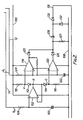
- FIG. 2 shows one form which the circuit of the comparator unit 70 can take.
- the signal Vm on line 74 is applied, across a smoothing capacitor 100, to the input of a buffer 102 via a resistor 104.
- the output Vm is applied to a potential divider connected between circuit supply lines 106 and 108, the potential divider comprising a resistor 110, a diode 112, another diode 114, and a resistor 116.
- the voltage applied across the supply lines 106 and 108 is stabilised, and the diodes 112 and 114 are therefore biased to fixed points on their operating characteristics. Therefore, the voltage at point A exceeds the voltage at B by a fixed amount, while the voltage at point C is less than the voltage at B by the same fixed amount. Therefore, if point B is at a voltage Vm, then point A is at a voltage (Vm+8V) and the voltage at point C is (V M -8v).
- Points A and C are each connected to the input of a respective one of two comparators 118 and 120.
- the second inputs of these comparators are fed, across a capacitor 122, with the signal Vs via the line 72 and a resistor 124.
- Each comparator 118, 120 therefore compares the voltage at the point A or C with the voltage Vs. If the voltage Vs falls below (Vm-8V) at point C, comparator 120 changes state and drives a current through an output diode 126. Similarly, if the voltage Vs rises above the voltage (Vm+8V) at point A, then comparator 118 changes state and drives an output current through an output diode 125. Diodes 125 and 126 are connected to form an OR gate, and when current is driven through either of them, in response to one or other of the comparators 118 and 120 changing state, this current flows through a resistor 127 and produces a pulse through a capacitor 128. This pulse passes through a diode 130 to the line 68 so as to cause the control unit 50 ( Figure 1) to disable the system.
- resistors may be used, so that, in that case, the limits ⁇ 8V will not be constant but will be variable.
- Figure 3 shows another form which the circuit of the comparator unit 70 can take. In fact, Figure 3 also includes the circuit of the memory 36 and shows the control unit 50.
- the speed signal Vs on line 21 is applied to the memory 36 through a resistor 200 and is fed to the non-inverting input of an operational amplifier 202.
- Resistor 200 acts in conjunction with a capacitor 201 to filter out ripple from Vs.
- the amplifier output is fed through a resistor 204 and a field effect transistor 206 to one plate of a capacitor 208 which forms the storage unit of the memory 36 as will be explained in detail.
- the capacitor controls the potential applied to the gate electrode of a further field effect transistor 210.
- the field effect transistor 210 has its source circuit supplied with a substantially constant current through a circuit comprising an adjustable resistor 212, fixed resistors 214 and 216, the collector-emitter path of an npn transistor 218 and a resistor 220.
- the conduction of transistor 218 is controlled by a potential divider circuit comprising a resistor 222 in series with a diode 224 and another resistor 226.
- a feedback line 228 connects the junction of resistors 214 and 216 to the inverting input of the operational amplifier 202.
- the conduction of transistor 218 is pre-set so that the current through the FET 210 is at a value at which the gate-source voltage of the FET is least sensitive to changes in ambient temperature. Such temperature changes will themselves effect the conduction of transistor 218, but this is offset by the effect which they have on the current through the diode 224. The result is, therefore, that the FET 210 is substantially unaffected by ambient temperature changes.
- the comparator unit 70 includes two comparators 230 and 232.
- the inverting input of comparator 230 is connected to the junction between resistors 212 and 214 (point A), and the non-inverting input of comparator 232 is connected to the junction between resistor 216 and transistor 218 (point C).
- the other inputs of the comparators 230 and 232 are connected together to receive the signal Vs on the line 72 (see Figure 1).
- the outputs of the comparators 230 and 232 are connected together through diodes 234 and 236 and feed a resistor 240 via a capacitor 238 with a resistor 242 in parallel.
- the voltage developed across resistor 240 is fed to the control unit 50 on the line 68 (see also Figure 1).
- the line 74 of Figure 1 which feeds the signal dependent on the desired vehicle speed to the comparator unit 70, can be considered to the line feeding the resistors 214 and 216 from the FET 210.
- the driver only momentarily operates switch 48, and when he reeases it FET 206 is rendered non-conductive by the control unit 50 and the charge on capacitor 208 is thus held at the immediately preceding value.
- This value is of course a value such that the voltage at the point B represents the speed at which the vehicle is required to travel.
- the constant current flowing through resistors 214 and 216 has the effect that the voltage at point A exceeds the voltage at point B by a fixed amount (8V) while the voltage at point C is less than the voltage at point B by the same fixed amount (8V).
- Each comparator 230 and 232 therefore compares the actual value of the voltage Vs, received via line 72 and which will vary as the speed of the vehicle varies, with the voltage applied to its other input which will represent a limit (+8V or -8V) above or below the voltage at point B and thus above or below the signal stored in the memory 36.
- the voltages at point A and C thus represent the limits applied by the comparator unit 70 to the maximum speed error.
- one or other of the comparators 230 and 232 will be activated, depending on the direction of the speed error, and will drive a current through its output diode 234 and 236.
- the resultant current will charge capacitor 238 which will produce a pulse across resistor 240 and thus generate a signal on line 68 which will disable the speed control system via the control unit 50 and the line 60 ( Figure 1).
- the previously activated comparator 230 or 232 will resume its quiescent state. When this happens, a respective one of the diodes 234 and 236 will become reverse-biased and capacitor 238 will discharge through resistor 242.
- the comparator unit 70 is thus reset- though the speed control system will not be brought back into action merely in response to this. In order to bring the speed control system back into operation, it is necessary for the driver to re-activate it. This will cause the control unit 50 to remove the inhibiting signal on line 60 ( Figure 1) so that the drive circuit 46 can once more control the vehicle's speed to the level represented by the signal which is still stored in the capacitor 208.
- the vehicle may also be provided with a "resume" control which can be activated by the driver after the comparator unit 70 has produced the disabling signal on line 68.
- the control unit 50 again removes the inhibiting signal on line 60 ( Figure 1) so as to allow the drive circuit 46 to take over speed control again. This can be carried out even if the vehicle speed is outside the upper and lower speed limits applied to the comparators 230 and 232: this is because the comparator unit acts by applying a pulse on line 68 and, once such pulse has been produced, the capacitor 238 is held fully charged and the voltage level subsequently maintained across resistor 240 is insufficient to energise line 48.
- Resistors 244 and 246 provide a small amount of positive feedback to the non-inverting inputs of the comparators 230 and 232 and ensure that they switch cleanly.
- the voltage at point B represents the charge stored on the memory capacitor 208, and thus represents the desired speed
- the voltage Vm being the input to the error amplifier 42 ( Figure 1), is not taken directly from point B but from the junction between FET 210 and the variable resistor 212. This enables the resistor 212 to be adjusted on test so as to alter the cruising speed of the vehicle relative to the actual speed signal stored in the memory. This adjustment can be made if the vehicle is found not to cruise exactly at the speed memorised on engagement of the system.
- the use of the operational amplifier 202 is advantageous because it makes the voltage at point B substantially the same as the voltage Vs as soon as the system is engaged, and ensures, therefore, that it is not necessary for the field effect transistors from which FET 110 is to be selected to be specially selected or pre-graded according to their gate-source voltage-the operational amplifier 202 compensates for variations between the gate-source voltage of different field effect transistors.
- the variable resistor 212 does not therefore have to be adjustable to compensate the actual gate-source voltage of the particular field effect transistor used for the FET 210 and can therefore be used merely to adjust the actual cruising speed of the vehicle relative to actual stored speed as explained above.
- the operational amplifier 202 When the system is engaged, the operational amplifier 202 very rapidly brings the voltage at point B to the value of Vs, and therefore the length of the engaging period does not substantially affect the accuracy of the actual speed signal stored in the memory capacitor 208.
- the operational amplifier 202 isolates the memory capacitor 208 from the filtering capacitor 201, and therefore the action of charging up capacitor 208 does not affect the voltage across capacitor 201 or the actual voltage Vs. This gives a smoother and more accurate engagement of the speed control system.
- circuitry shown in Figure 3 is advantageous over that shown in Figure 2 because the potential drops across resistors 214 and 21.6 (which define the limits applied by the comparator unit 70 above and below the set speed) are dependent only on the constant current.
Landscapes
- Engineering & Computer Science (AREA)
- Chemical & Material Sciences (AREA)
- Combustion & Propulsion (AREA)
- Transportation (AREA)
- Mechanical Engineering (AREA)
- Controls For Constant Speed Travelling (AREA)
- Control Of Velocity Or Acceleration (AREA)
- Control Of Vehicle Engines Or Engines For Specific Uses (AREA)
- Electrical Control Of Air Or Fuel Supplied To Internal-Combustion Engine (AREA)
Description
- The invention relates to vehicle speed control systems arranged when rendered operative to control the engine of the vehicle so as to tend to hold the vehicle to run at a desired speed.
- In normal circumstances, such systems will hold the actual vehicle speed very accurately to the desired speed. However, abnormal conditions can arise in which, owing possibly to special road conditions, lack of engine power, or a fault in the control system itself, the actual vehicle speed diverges from the desired speed significantly. The invention is concerned with this problem.
- A vehicle speed control system is known (see U.S. Patent No. 4072206) in which the upper and lower cut-out limits are provided which automatically cut the speed control system out of operation should the vehicle speed exceed a fixed limit close to the vehicle's maximum speed or fall below a low fixed limit. However, such an arrangement does not deal with the problem outlined above-because in normal circumstances, assuming that the desired vehicle speed as well within the vehicle's normal speed range, the vehicle's speed would have to change very substantially from the desired speed before it reached on of the fixed limits, and during the whole of this time the speed control system would be trying to rectify the increasing speed error. This could well create a dangerous situation.
- Accordingly, a vehicle speed control system arranged when rendered operative to control the engine of the vehicle so as to tend to hold the vehicle to run at a desired speed, and including generating circuitry for generating signals representing upper and lower limits of a speed range in which the desired speed lies, comparing circuitry operative to compare the actual vehicle's speed with the said limits, and disabling means operative to disable the speed control system when the actual vehicle's speed falls outside the speed speed range, is characterised in that the upper and lower speed limits define a relatively narrow speed range and both change in value in the same direction as any change in value of the desired speed.
- Vehicle speed control systems embodying the invention will now be described with reference to the accompanying drawings in which:
- Figure 1 is a block circuit diagram of the system;
- Figure 2 is a more detailed circuit diagram of part of the system; and
- Figure 3 corresponds to Figure 2 but shows a different form which that part of the circuit may take.
- The systems to be described are for automatically controlling a motor vehicle to run at a predetermined speed which is set by the driver. Once the speed has been selected and set by the driver, the system operates automatically to hold the vehicle at that speed, subject, of course, to the speed being within the capability of the vehicle having regard to the gradient and other features. In the system to be described, if the speed required becomes outside the capability of the vehicle, the system is automatically switched off, whereafter control of the vehicle speed is resumed by the driver.
- Figure 1 shows the
engine 10 of the motor vehicle driving thepropellor shaft 12 through agearbox 14, the speed of the engine being regulated by means of athrottle control 15. Thecontrol 15 will normally form a part of the engine carburetter and is arranged to be adjustable by the driver's throttle pedal in the usual way. In addition, however, it is connected to be adjustable by means of athrottle actuator 16. - It will be appreciated that in relation to the application of the system to a diesel-engine- powered vehicle, the
throttle control 15 would be replaced by the equivalent engine power control device. - A
line 17 carries a pulsating electrical signal whose frequency is dependent on the road speed of the vehicle. This signal is derived in a road speed transducer which may be of any suitable type. For example, it can comprise an electromagnetic transducer sensing the rotational speed of the propeller shaft of the vehicle. However, various other means can be used for producing an electrical signal dependent on the road speed of the vehicle. - The speed dependnet signal on
line 17 is then passed to a frequency-to-voltage converter 22 which produces an output voltage Vs on aline 21 dependent on engine speed. The system may be arranged so that either the signal Vs is proportional to engine speed or inversely proportional to engine speed. - The
circuit 22 may take any suitable form. It may, for example, comprise a limiting amplifier and monostable circuit for converting the pulse signal online 17 into a rectangular wave of constant amplitude and width followed by a smoothing circuit. - The speed-dependent signal Vs is then fed to a
memory 36 and is also fed directly to afilter 38. Thememory 36 and thefilter 38 produce respective outputs Vm and Vf which are both fed to anerror amplifier 42. The latter drives adrive circuit 46 which in turn drives thethrottle actuator 16. - The operation of the system as so far described is as follows.
- When the driver wishes to bring the system into operation to control the vehicle to run at a particular speed, he accelerates the vehicle up to that speed (or decelerates it down to that speed) and momentarily closes a
switch 48 when the vehicle is running at the desired speed. This momentary closure ofswitch 48 causes acontrol unit 50 to activate amemory 36 by mens of aline 52 and feeds into the memory 36 a signal dependent on that vehicle speed. This signal becomes stored in thememory 36 when theswitch 48 is once more open, and is fed as the signal Vm to one input of theerror amplifier 42. The other input of theamplifier 42 receives the signal Vf from thefilter 38. - The relationship between the signal Vf and the signal Vs depends on the characteristic of the filter. In this embodiment, Vf is affected by the rate of change of Vs so as to tend to change by a greater amount when Vs is changing rapidly than when Vs is changing slowly, and therefore leads on Vs when the vehicle speed is changing rapidly, in either sense.
- For so long as the vehicle remains at the desired speed, the two inputs to the
error amplifier 42 will be equal and thethrottle actuator 16 will hold the throttle control unchanged. If the vehicle tends to change speed from the desired setting, however, there will be a resultant change in engine speed and Vf will change. Theerror amplifier 42 will produce a corresponding output which will energise thedrive circuit 46 in such a direction as to cause thethrottle actuator 16 to adjust the position of thethrottle control 15 so as to tend to bring the vehicle back to the desired speed. - The system as so far described may for example take the form disclosed in our copending Patent Application GB-A=1570887.
- The
control unit 50 checks the various operating parameters of the vehicle to determine whether the system can be brought into operation (in response to operation of theswitch 48 by the driver) or, if the system is already in operation, whether it should be automatically switched off. Thecontrol unit 50 has several input lines by which it receives signals dependent on various operating parameters of the vehicle. For example, the unit has aninput line 58 which senses when the vehicle's brakes are applied (as by sensing for electrical conditions in the vehicle brake lamp circuit). When the signal online 58 indicates that the driver has applied the vehicle brakes, theunit 58 produces a disabling signal on aline 60 which deactivates thedrive circuit 46 so as to disable the system. Other input lines to the unit 56, for example theinput lines unit 50 would energiseline 60 to disable the system. - The foregoing illustrate some of the vehicle operating parameters to which the
unit 50 may respond. - The
unit 50 may also be arranged to check the vehicle operating parameters before the speed control system is engaged by the driver. If theunit 50 determines that the operating parameters are in a satisfactory condition when the driver operates the switch to engage the system, then, by means of theline 52, it sets thememory 36 into condition for storing a desired speed signal in the manner explained above, and of course enables the system by means of an appropriate signal on theline 60. Thecontrol unit 50 may be arranged so that, once the system is in operation, the unit only disables the drive circuit 46 (by means of line 60) in response to occurrence of the appropriate signal on one of itsinput lines memory 36. Therefore, the previously-stored signal inmemory 36, representing desired speed, remains stored, and the driver may manually re-engage the system (provided that the condition of the vehicle parameter which caused thecontrol unit 50 to disable the system has now been removed), and the system will then bring the vehicle speed up to the desired value represented by the stored signal. Other input signals to thecontrol unit 50 may, however, be arranged to cause theunit 50 not only to disable the system, but also to clear thememory 36 by means of theline 52. - As shown, the
control unit 50 also has afurther input line 68 from acomparator unit 70. The comparator unit has afirst input line 72 which is fed from theline 21 and carries the signal Vs. Thesecond input line 74 to thecomparator unit 70 carries the signal Vm from thememory 36. Thecomparator unit 70 compares Vs and Vm to determine the speed error at any time. In a manner to be explained in more detail with reference to Figures 2 and 3, the comparator determines whether this speed error falls outside upper and lower limits and, if so, produces a signal online 68 which causes thecontrol unit 50 to disable the system via aline 60. - For example, the limits applied by the
comparator unit 70 to the speed error could be plus and minus 15 kilometres per hour. In other words, if the actual vehicle speed (represented by Vs) exceeds the desired vehicle speed (represented by Vm) by at least 15 kilometres per hour, or falls below the desired vehicle speed by at least 15 kilometres per hour, the system is disabled by thecontrol unit 50. - In this way, the system is disabled when the vehicle engine is not able to maintain the actual vehicle speed at or close to the desired vehicle speed, for example due to abnormal gradients or loss of engine power. The system is also disabled if for any other reason the speed becomes too high in relation to the desired speed.
- Figure 2 shows one form which the circuit of the
comparator unit 70 can take. - As shown in Figure 2, the signal Vm on
line 74 is applied, across asmoothing capacitor 100, to the input of abuffer 102 via aresistor 104. The output Vm is applied to a potential divider connected betweencircuit supply lines resistor 110, adiode 112, anotherdiode 114, and aresistor 116. The voltage applied across thesupply lines diodes - Points A and C are each connected to the input of a respective one of two
comparators capacitor 122, with the signal Vs via theline 72 and aresistor 124. - Each
comparator comparator 120 changes state and drives a current through anoutput diode 126. Similarly, if the voltage Vs rises above the voltage (Vm+8V) at point A, then comparator 118 changes state and drives an output current through anoutput diode 125.Diodes comparators resistor 127 and produces a pulse through acapacitor 128. This pulse passes through adiode 130 to theline 68 so as to cause the control unit 50 (Figure 1) to disable the system. - When the
particular comparator diode 132 clips the resultant negative pulse passing through thecapacitor 128. - Instead of the
diodes - Figure 3 shows another form which the circuit of the
comparator unit 70 can take. In fact, Figure 3 also includes the circuit of thememory 36 and shows thecontrol unit 50. - As shown in Figure 3, the speed signal Vs on
line 21 is applied to thememory 36 through aresistor 200 and is fed to the non-inverting input of anoperational amplifier 202.Resistor 200 acts in conjunction with acapacitor 201 to filter out ripple from Vs. The amplifier output is fed through aresistor 204 and afield effect transistor 206 to one plate of acapacitor 208 which forms the storage unit of thememory 36 as will be explained in detail. The capacitor controls the potential applied to the gate electrode of a furtherfield effect transistor 210. - The
field effect transistor 210 has its source circuit supplied with a substantially constant current through a circuit comprising anadjustable resistor 212, fixedresistors npn transistor 218 and aresistor 220. The conduction oftransistor 218 is controlled by a potential divider circuit comprising a resistor 222 in series with adiode 224 and anotherresistor 226. - A
feedback line 228 connects the junction ofresistors operational amplifier 202. - The conduction of
transistor 218 is pre-set so that the current through theFET 210 is at a value at which the gate-source voltage of the FET is least sensitive to changes in ambient temperature. Such temperature changes will themselves effect the conduction oftransistor 218, but this is offset by the effect which they have on the current through thediode 224. The result is, therefore, that theFET 210 is substantially unaffected by ambient temperature changes. - The
comparator unit 70 includes twocomparators comparator 230 is connected to the junction betweenresistors 212 and 214 (point A), and the non-inverting input ofcomparator 232 is connected to the junction betweenresistor 216 and transistor 218 (point C). The other inputs of thecomparators comparators diodes resistor 240 via acapacitor 238 with a resistor 242 in parallel. The voltage developed acrossresistor 240 is fed to thecontrol unit 50 on the line 68 (see also Figure 1). - In Figure 3, the
line 74 of Figure 1, which feeds the signal dependent on the desired vehicle speed to thecomparator unit 70, can be considered to the line feeding theresistors FET 210. - The operation of the circuit of Figure 3 will now be described.
- When the driver wishes to bring the speed control system into operation, he momentarily closes
switch 48 which causes thecontrol unit 50 to energiseline 52 to as to renderFET 206 conductive. Theoperational amplifier 202 is now connected in a closed loop through the conductingFET 206, the gate and source ofFET 210, theresistors feedback line 228. Theamplifier 202 therefore operates to make the voltage at its inverting input virtually the same as at the non-inverting input, thus making the voltage at point B substantially equal to the value of Vs at that time. In addition,capacitor 208 becomes charged to the voltage present at the gate ofFET 210. - The driver only momentarily operates
switch 48, and when he reeases itFET 206 is rendered non-conductive by thecontrol unit 50 and the charge oncapacitor 208 is thus held at the immediately preceding value. This value is of course a value such that the voltage at the point B represents the speed at which the vehicle is required to travel. - In the
comparator unit 70, the constant current flowing throughresistors comparator line 72 and which will vary as the speed of the vehicle varies, with the voltage applied to its other input which will represent a limit (+8V or -8V) above or below the voltage at point B and thus above or below the signal stored in thememory 36. - The voltages at point A and C thus represent the limits applied by the
comparator unit 70 to the maximum speed error. - If the vehicle speed diverges from the desired value by more than a predetermined amount, represented by these limits, one or other of the
comparators output diode capacitor 238 which will produce a pulse acrossresistor 240 and thus generate a signal online 68 which will disable the speed control system via thecontrol unit 50 and the line 60 (Figure 1). - If and when the speed changes so that the speed error is reduced and now falls within the limits set by the voltages at points A and C, the previously activated
comparator diodes capacitor 238 will discharge through resistor 242. Thecomparator unit 70 is thus reset- though the speed control system will not be brought back into action merely in response to this. In order to bring the speed control system back into operation, it is necessary for the driver to re-activate it. This will cause thecontrol unit 50 to remove the inhibiting signal on line 60 (Figure 1) so that thedrive circuit 46 can once more control the vehicle's speed to the level represented by the signal which is still stored in thecapacitor 208. - The vehicle may also be provided with a "resume" control which can be activated by the driver after the
comparator unit 70 has produced the disabling signal online 68. In response to such operation, thecontrol unit 50 again removes the inhibiting signal on line 60 (Figure 1) so as to allow thedrive circuit 46 to take over speed control again. This can be carried out even if the vehicle speed is outside the upper and lower speed limits applied to thecomparators 230 and 232: this is because the comparator unit acts by applying a pulse online 68 and, once such pulse has been produced, thecapacitor 238 is held fully charged and the voltage level subsequently maintained acrossresistor 240 is insufficient to energiseline 48. -
Resistors comparators - Although the voltage at point B represents the charge stored on the
memory capacitor 208, and thus represents the desired speed, the voltage Vm, being the input to the error amplifier 42 (Figure 1), is not taken directly from point B but from the junction betweenFET 210 and thevariable resistor 212. This enables theresistor 212 to be adjusted on test so as to alter the cruising speed of the vehicle relative to the actual speed signal stored in the memory. This adjustment can be made if the vehicle is found not to cruise exactly at the speed memorised on engagement of the system. - The use of the
operational amplifier 202 is advantageous because it makes the voltage at point B substantially the same as the voltage Vs as soon as the system is engaged, and ensures, therefore, that it is not necessary for the field effect transistors from whichFET 110 is to be selected to be specially selected or pre-graded according to their gate-source voltage-theoperational amplifier 202 compensates for variations between the gate-source voltage of different field effect transistors. Thevariable resistor 212 does not therefore have to be adjustable to compensate the actual gate-source voltage of the particular field effect transistor used for theFET 210 and can therefore be used merely to adjust the actual cruising speed of the vehicle relative to actual stored speed as explained above. - When the system is engaged, the
operational amplifier 202 very rapidly brings the voltage at point B to the value of Vs, and therefore the length of the engaging period does not substantially affect the accuracy of the actual speed signal stored in thememory capacitor 208. - In addition, the
operational amplifier 202 isolates thememory capacitor 208 from thefiltering capacitor 201, and therefore the action of charging upcapacitor 208 does not affect the voltage acrosscapacitor 201 or the actual voltage Vs. This gives a smoother and more accurate engagement of the speed control system. - The circuitry shown in Figure 3 is advantageous over that shown in Figure 2 because the potential drops across
resistors 214 and 21.6 (which define the limits applied by thecomparator unit 70 above and below the set speed) are dependent only on the constant current.
Claims (13)
Applications Claiming Priority (2)
| Application Number | Priority Date | Filing Date | Title |
|---|---|---|---|
| GB7927128 | 1979-08-03 | ||
| GB7927128 | 1979-08-03 |
Publications (2)
| Publication Number | Publication Date |
|---|---|
| EP0023677A1 EP0023677A1 (en) | 1981-02-11 |
| EP0023677B1 true EP0023677B1 (en) | 1984-04-04 |
Family
ID=10506977
Family Applications (1)
| Application Number | Title | Priority Date | Filing Date |
|---|---|---|---|
| EP80104368A Expired EP0023677B1 (en) | 1979-08-03 | 1980-07-24 | Improvements in and relating to vehicle speed control systems |
Country Status (10)
| Country | Link |
|---|---|
| US (1) | US4336566A (en) |
| EP (1) | EP0023677B1 (en) |
| JP (1) | JPS5624613A (en) |
| BE (1) | BE884608A (en) |
| DE (1) | DE3067342D1 (en) |
| DK (1) | DK148336B (en) |
| FR (1) | FR2463022B1 (en) |
| IE (1) | IE50223B1 (en) |
| IT (1) | IT1136055B (en) |
| ZA (1) | ZA804694B (en) |
Families Citing this family (17)
| Publication number | Priority date | Publication date | Assignee | Title |
|---|---|---|---|---|
| EP0043660B1 (en) * | 1980-07-08 | 1986-04-23 | Automotive Products Public Limited Company | Clutch control system |
| GB2081934B (en) * | 1980-08-08 | 1984-03-07 | Ass Eng Ltd | Automatic speed control systems |
| ZA814691B (en) * | 1980-08-08 | 1983-02-23 | Ass Eng Ltd | Automatic speed control systems |
| DE3410323C3 (en) * | 1984-03-21 | 1995-05-18 | Bosch Gmbh Robert | Device for controlling the fuel metering in an internal combustion engine |
| US4656407A (en) * | 1985-06-14 | 1987-04-07 | A.R.A. Manufacturing Company Of Delware, Inc. | Electric motor servo control system and method |
| DE3542624A1 (en) * | 1985-12-03 | 1987-06-04 | Michael Meyerle | CONTROL DEVICE FOR A CONTINUOUSLY ADJUSTABLE GEARBOX FOR MOTOR VEHICLES |
| US4838780A (en) * | 1986-12-24 | 1989-06-13 | Honda Giken Kogyo Kabushiki Kaisha | Constant speed running control device for automobile |
| US4849892A (en) * | 1987-03-06 | 1989-07-18 | Chrysler Motors Corporation | Method of determining and using an acceleration correction in an integrated acceleration based electronic speed control system for vehicles |
| US4890231A (en) * | 1987-03-06 | 1989-12-26 | Chrysler Motors Corporation | Method of disabling a resume switch in an electronic speed control system for vehicles |
| US4896267A (en) * | 1987-03-06 | 1990-01-23 | Chrysler Motors Corporation | Electronic speed control system for vehicles, a method of determining the condition of a manual transmission clutch and of a park/neutral gear in an automatic transmission |
| EP0728612B1 (en) * | 1987-03-06 | 2004-09-01 | Meyerle, Hannelore | Control device for a continuously variable transmission for motor vehicles |
| US4860210A (en) * | 1987-03-06 | 1989-08-22 | Chrysler Motors Corporation | Method of determining and using a filtered speed error in an integrated acceleration based electronic speed control system for vehicles |
| DE3719812C2 (en) * | 1987-06-13 | 1998-05-14 | Mannesmann Vdo Ag | Control system with an actuator for regulating the performance of an internal combustion engine with a subordinate manual transmission |
| JPS6452530A (en) * | 1987-08-19 | 1989-02-28 | Fuji Heavy Ind Ltd | Vehicle control unit |
| JPH01122735A (en) * | 1987-11-06 | 1989-05-16 | Nissan Motor Co Ltd | Constant speed running device |
| US5679740A (en) * | 1996-06-13 | 1997-10-21 | Cytec Technology Corp. | Mechanically stable self inverting water-in-oil polymer emulsions containing carboxylated ethoxylated phenols or alcohols |
| US20100082180A1 (en) * | 2008-10-01 | 2010-04-01 | Honeywell International Inc. | Errant vehicle countermeasures |
Family Cites Families (9)
| Publication number | Priority date | Publication date | Assignee | Title |
|---|---|---|---|---|
| US3570622A (en) * | 1968-12-27 | 1971-03-16 | Rca Corp | Speed control for motor vehicles |
| US3757130A (en) * | 1969-12-19 | 1973-09-04 | Hitachi Ltd | Overspeed preventive apparatus for engines |
| JPS50155892A (en) * | 1974-05-13 | 1975-12-16 | ||
| US3952829A (en) * | 1975-05-22 | 1976-04-27 | Dana Corporation | Vehicle speed control circuit |
| GB1570887A (en) * | 1976-03-13 | 1980-07-09 | Ass Eng Ltd | Speed responsive systems |
| GB1584254A (en) * | 1976-06-24 | 1981-02-11 | Ass Eng Ltd | Speed responsive systems |
| JPS53127991A (en) * | 1977-04-14 | 1978-11-08 | Aisin Seiki Co Ltd | Set speed signal memory apparatus for vehicle constant speed travelling system |
| GB1602487A (en) * | 1978-05-31 | 1981-11-11 | Ass Eng Ltd | Vehicle speed control systems |
| DE2834805C2 (en) * | 1978-08-09 | 1985-03-14 | Messerschmitt-Bölkow-Blohm GmbH, 8012 Ottobrunn | Circuit for monitoring a direct voltage against a reference voltage within adjustable tolerance limits |
-
1980
- 1980-07-24 US US06/171,973 patent/US4336566A/en not_active Expired - Lifetime
- 1980-07-24 DE DE8080104368T patent/DE3067342D1/en not_active Expired
- 1980-07-24 EP EP80104368A patent/EP0023677B1/en not_active Expired
- 1980-07-31 IT IT09507/80A patent/IT1136055B/en active
- 1980-08-01 BE BE0/201631A patent/BE884608A/en not_active IP Right Cessation
- 1980-08-01 ZA ZA00804694A patent/ZA804694B/en unknown
- 1980-08-01 FR FR8017075A patent/FR2463022B1/en not_active Expired
- 1980-08-01 DK DK333680AA patent/DK148336B/en not_active Application Discontinuation
- 1980-08-01 IE IE1624/80A patent/IE50223B1/en unknown
- 1980-08-04 JP JP10647680A patent/JPS5624613A/en active Pending
Also Published As
| Publication number | Publication date |
|---|---|
| IE50223B1 (en) | 1986-03-05 |
| BE884608A (en) | 1981-02-02 |
| IT8009507A0 (en) | 1980-07-31 |
| IT1136055B (en) | 1986-08-27 |
| ZA804694B (en) | 1981-08-26 |
| DK148336B (en) | 1985-06-10 |
| JPS5624613A (en) | 1981-03-09 |
| DK333680A (en) | 1981-02-04 |
| IE801624L (en) | 1981-02-03 |
| FR2463022A1 (en) | 1981-02-20 |
| US4336566A (en) | 1982-06-22 |
| FR2463022B1 (en) | 1986-01-24 |
| EP0023677A1 (en) | 1981-02-11 |
| DE3067342D1 (en) | 1984-05-10 |
Similar Documents
| Publication | Publication Date | Title |
|---|---|---|
| US4336566A (en) | Vehicle speed control systems | |
| US4433390A (en) | Power processing reset system for a microprocessor responding to sudden deregulation of a voltage | |
| EP0378075B1 (en) | Control device for vehicle A.C. generator | |
| US5216350A (en) | Method and system for controlling an alternator | |
| US4143307A (en) | Motor speed control circuit apparatus | |
| US3621370A (en) | Generator load control system | |
| HK1003023B (en) | Control device for vehicle a.c. generator | |
| GB1516623A (en) | Apparatus for controlling the speed of motor vehicles | |
| US4354467A (en) | Vehicle speed control systems | |
| US4372265A (en) | Control circuit for engine speed governor with power take off | |
| US5083273A (en) | Temperature detection for electromagentic clutch of vehicle | |
| US4315205A (en) | Generation control apparatus for vehicle generators | |
| US4337424A (en) | Speed control for a rotary machine | |
| US4555657A (en) | Voltage regulator for alternator of vehicle | |
| JPS6289434A (en) | Voltage regulator for charging generator on electric rollingstock | |
| US4739244A (en) | Vehicle generator with acceleration control override | |
| GB2056125A (en) | Vehicle speed control system | |
| US5225751A (en) | Power supply circuit for a motor | |
| JPS5844233A (en) | Controller for quantity of fuel supplied of internal combustion engine | |
| US4129819A (en) | Voltage regulator circuit for motor vehicle generator with feedback to oppose regulator transients | |
| US3935520A (en) | DC motor regulator | |
| US4249498A (en) | Apparatus for correcting a fuel apportionment signal in an internal combustion engine | |
| US4716355A (en) | Device for controlling a charging generator | |
| US3350619A (en) | Battery charging circuit responsive to generator output voltage and current | |
| US4400757A (en) | Automatic speed control systems |
Legal Events
| Date | Code | Title | Description |
|---|---|---|---|
| PUAI | Public reference made under article 153(3) epc to a published international application that has entered the european phase |
Free format text: ORIGINAL CODE: 0009012 |
|
| AK | Designated contracting states |
Designated state(s): DE LU NL SE |
|
| 17P | Request for examination filed |
Effective date: 19810707 |
|
| GRAA | (expected) grant |
Free format text: ORIGINAL CODE: 0009210 |
|
| AK | Designated contracting states |
Designated state(s): DE LU NL SE |
|
| REF | Corresponds to: |
Ref document number: 3067342 Country of ref document: DE Date of ref document: 19840510 |
|
| PGFP | Annual fee paid to national office [announced via postgrant information from national office to epo] |
Ref country code: SE Payment date: 19840630 Year of fee payment: 5 |
|
| PG25 | Lapsed in a contracting state [announced via postgrant information from national office to epo] |
Ref country code: LU Free format text: LAPSE BECAUSE OF NON-PAYMENT OF DUE FEES Effective date: 19840731 |
|
| PGFP | Annual fee paid to national office [announced via postgrant information from national office to epo] |
Ref country code: DE Payment date: 19840809 Year of fee payment: 5 |
|
| RAP2 | Party data changed (patent owner data changed or rights of a patent transferred) |
Owner name: AE PLC |
|
| RAP2 | Party data changed (patent owner data changed or rights of a patent transferred) |
Owner name: AE PLC |
|
| PLBI | Opposition filed |
Free format text: ORIGINAL CODE: 0009260 |
|
| PLBI | Opposition filed |
Free format text: ORIGINAL CODE: 0009260 |
|
| 26 | Opposition filed |
Opponent name: VDO ADOLF SCHINDLING AG Effective date: 19840411 |
|
| 26 | Opposition filed |
Opponent name: DAIMLER-BENZ AKTIENGESELLSCHAFT Effective date: 19841214 |
|
| NLR1 | Nl: opposition has been filed with the epo |
Opponent name: VDO ADOLF SCHINDLING AG. |
|
| NLR1 | Nl: opposition has been filed with the epo |
Opponent name: DAIMLER-BENZ AG |
|
| PGFP | Annual fee paid to national office [announced via postgrant information from national office to epo] |
Ref country code: NL Payment date: 19850731 Year of fee payment: 6 |
|
| RDAG | Patent revoked |
Free format text: ORIGINAL CODE: 0009271 |
|
| STAA | Information on the status of an ep patent application or granted ep patent |
Free format text: STATUS: PATENT REVOKED |
|
| 27W | Patent revoked |
Effective date: 19851031 |
|
| NLR2 | Nl: decision of opposition | ||
| EUG | Se: european patent has lapsed |
Ref document number: 80104368.8 Effective date: 19870518 |