EP0023122B1 - A tongue and buckle fastener for a safety belt harness - Google Patents
A tongue and buckle fastener for a safety belt harness Download PDFInfo
- Publication number
- EP0023122B1 EP0023122B1 EP80302385A EP80302385A EP0023122B1 EP 0023122 B1 EP0023122 B1 EP 0023122B1 EP 80302385 A EP80302385 A EP 80302385A EP 80302385 A EP80302385 A EP 80302385A EP 0023122 B1 EP0023122 B1 EP 0023122B1
- Authority
- EP
- European Patent Office
- Prior art keywords
- tongue
- ejector
- latching member
- recess
- buckle
- Prior art date
- Legal status (The legal status is an assumption and is not a legal conclusion. Google has not performed a legal analysis and makes no representation as to the accuracy of the status listed.)
- Expired
Links
- 230000037431 insertion Effects 0.000 description 7
- 238000003780 insertion Methods 0.000 description 7
- 230000000881 depressing effect Effects 0.000 description 2
- 229910000831 Steel Inorganic materials 0.000 description 1
- 238000010276 construction Methods 0.000 description 1
- 230000000994 depressogenic effect Effects 0.000 description 1
- 230000000694 effects Effects 0.000 description 1
- 230000002708 enhancing effect Effects 0.000 description 1
- 229920003023 plastic Polymers 0.000 description 1
- 239000004033 plastic Substances 0.000 description 1
- 230000000717 retained effect Effects 0.000 description 1
- 239000010959 steel Substances 0.000 description 1
Images


Classifications
-
- A—HUMAN NECESSITIES
- A44—HABERDASHERY; JEWELLERY
- A44B—BUTTONS, PINS, BUCKLES, SLIDE FASTENERS, OR THE LIKE
- A44B11/00—Buckles; Similar fasteners for interconnecting straps or the like, e.g. for safety belts
- A44B11/25—Buckles; Similar fasteners for interconnecting straps or the like, e.g. for safety belts with two or more separable parts
- A44B11/2503—Safety buckles
- A44B11/2507—Safety buckles actuated by a push-button
- A44B11/2523—Safety buckles actuated by a push-button acting parallel to the main plane of the buckle and in the same direction as the fastening action
-
- Y—GENERAL TAGGING OF NEW TECHNOLOGICAL DEVELOPMENTS; GENERAL TAGGING OF CROSS-SECTIONAL TECHNOLOGIES SPANNING OVER SEVERAL SECTIONS OF THE IPC; TECHNICAL SUBJECTS COVERED BY FORMER USPC CROSS-REFERENCE ART COLLECTIONS [XRACs] AND DIGESTS
- Y10—TECHNICAL SUBJECTS COVERED BY FORMER USPC
- Y10T—TECHNICAL SUBJECTS COVERED BY FORMER US CLASSIFICATION
- Y10T24/00—Buckles, buttons, clasps, etc.
- Y10T24/45—Separable-fastener or required component thereof [e.g., projection and cavity to complete interlock]
- Y10T24/45225—Separable-fastener or required component thereof [e.g., projection and cavity to complete interlock] including member having distinct formations and mating member selectively interlocking therewith
- Y10T24/45602—Receiving member includes either movable connection between interlocking components or variable configuration cavity
- Y10T24/45623—Receiving member includes either movable connection between interlocking components or variable configuration cavity and operator therefor
- Y10T24/4566—Receiving member includes either movable connection between interlocking components or variable configuration cavity and operator therefor including slidably connected and guided element on receiving member
-
- Y—GENERAL TAGGING OF NEW TECHNOLOGICAL DEVELOPMENTS; GENERAL TAGGING OF CROSS-SECTIONAL TECHNOLOGIES SPANNING OVER SEVERAL SECTIONS OF THE IPC; TECHNICAL SUBJECTS COVERED BY FORMER USPC CROSS-REFERENCE ART COLLECTIONS [XRACs] AND DIGESTS
- Y10—TECHNICAL SUBJECTS COVERED BY FORMER USPC
- Y10T—TECHNICAL SUBJECTS COVERED BY FORMER US CLASSIFICATION
- Y10T24/00—Buckles, buttons, clasps, etc.
- Y10T24/45—Separable-fastener or required component thereof [e.g., projection and cavity to complete interlock]
- Y10T24/45225—Separable-fastener or required component thereof [e.g., projection and cavity to complete interlock] including member having distinct formations and mating member selectively interlocking therewith
- Y10T24/45602—Receiving member includes either movable connection between interlocking components or variable configuration cavity
- Y10T24/45623—Receiving member includes either movable connection between interlocking components or variable configuration cavity and operator therefor
- Y10T24/4566—Receiving member includes either movable connection between interlocking components or variable configuration cavity and operator therefor including slidably connected and guided element on receiving member
- Y10T24/4567—Receiving member includes either movable connection between interlocking components or variable configuration cavity and operator therefor including slidably connected and guided element on receiving member for shifting slidably connected and guided, nonself-biasing, interlocking component
-
- Y—GENERAL TAGGING OF NEW TECHNOLOGICAL DEVELOPMENTS; GENERAL TAGGING OF CROSS-SECTIONAL TECHNOLOGIES SPANNING OVER SEVERAL SECTIONS OF THE IPC; TECHNICAL SUBJECTS COVERED BY FORMER USPC CROSS-REFERENCE ART COLLECTIONS [XRACs] AND DIGESTS
- Y10—TECHNICAL SUBJECTS COVERED BY FORMER USPC
- Y10T—TECHNICAL SUBJECTS COVERED BY FORMER US CLASSIFICATION
- Y10T24/00—Buckles, buttons, clasps, etc.
- Y10T24/45—Separable-fastener or required component thereof [e.g., projection and cavity to complete interlock]
- Y10T24/45225—Separable-fastener or required component thereof [e.g., projection and cavity to complete interlock] including member having distinct formations and mating member selectively interlocking therewith
- Y10T24/45602—Receiving member includes either movable connection between interlocking components or variable configuration cavity
- Y10T24/45717—Receiving member includes either movable connection between interlocking components or variable configuration cavity having cavity with side walls and axially biased component capping end
Definitions
- This invention relates to a tongue and buckle fastener for a safety belt harness of the type in which the buckle includes a spring-loaded latching member, which moves transversely of the direction of tongue insertion, and a spring-loaded tongue ejector.
- a tongue and buckle fastener for a safety belt harness comprises a tongue having a head portion, a buckle having a passageway for receiving the tongue, a spring-loaded latching member which is movable transversely of the passageway between a latching position and a release position, and a spring-loaded tongue ejector which is slidable in the passageway, the ejector having a recess shaped to engage with the head portion of the tongue and disposed so that, when the tongue has been ejected, the latching member rests on a side face of the ejector with a corner overhanging the recess, said side face of the ejector having an abutment adjacent to said corner of the latching member which engages with the latching member to inhibit inward movement of the ejector, the head portion of the tongue being operative, when inserted into the recess in the ejector, to engage with said overhanging corner of the latching member, thereby to lift the latching member clear
- the latching plate has two corners overhanging opposite sides of the recess in the ejector and the side face thereof has two abutments, each adjacent to a respective corner. If the latching member is allowed a limited amount of tilting movement, it cannot be lifted clear of the abutments, except by simultaneous engagement with both projecting corners. It is difficult to achieve such simultaneous engagement except with the tongue itself, thereby further enhancing the buckle's resistance to tampering.
- the abutments on one side face of the ejector may conveniently take the form of one wall of a groove in said side face.
- the drawings show a tongue 1 and a buckle 2, similar to those illustrated in our United Kingdom Patent Application No. 7900356 (GB-A-2030205).
- the tongue 1 has a head portion 3 with a pair of latching shoulders 3a and 3b.
- the head portion 3 is radiused to provide a nose for engaging a similarly radiused recess in an ejector member described below.
- the buckle 2 comprises a housing 5 in which a push button 6 is slidably mounted for movement in the direction of the arrow 7.
- the housing 5 is of a two-part construction which is secured along both sides by interengaging hooked portions 10a, 10b.
- the housing 5 contains a pair of frame members 12a, 12b which are secured together with an intermediate mounting bracket portion 13 by a rivet 11.
- the frame members 12a, 12b are in the form of plates with cutouts 13a, 13b.
- the distance W ( Figure 2) between the plates 12a, 12b is slightly greater than the thickness of the tongue 1.
- the plates 12a, 12b therefore form a passageway 14 into which the tongue 1 can be inserted.
- the lower plate 12b has turned down portions 15b, 15c which serve to protect the lower end of the latching member 20 from any crushing loads which may be applied to the buckle in service.
- Plate 12b also has laterally extending portions 1 6a, 16b ( Figures 3 and 4) which serve as guides for a camming member 21, as will be explained hereinafter.
- An ejector 17 has a radiused recess 18 for engaging the radiused edge of the head portion 3 of the tongue 1.
- the rear portion of the ejector 17 is formed by a rectangular section portion 19, which projects into the respective cutouts 13a and 13b of plates 12a, 12b. This service to guide the ejector 17 longitudinally of the passageway 14 when the tongue is inserted.
- a circular section portion 22 with a chamfered edge serves to locate one end of a coil spring 23, the other end of which engages the ends of the cutouts 13a and 13b.
- a latching member 20 is in the form of a bridge having a pair of oppositely directed lateral shoulders 24a, 24b.
- the latching member 20 is also provided with a pair of downwardly directed feet 26a, 26b, the distance X therebetween ( Figure 4) being slightly larger than the breadth of the head portion 3 of the tongue 1.
- a pair of inwardly directed shoulders 27a, 27b adjoin the respective feet 26a, 26b.
- the distance Y ( Figure 5) between the shoulders 27a, 27b enables the radiused end of the head portion 3 of the tongue 1 to engage with the radiused recess 18 of the ejector 17.
- the shoulders 27a, 27b serve to engage the respective latching shoulders 3a, 3b of the tongue 1 when fully inserted into the buckle.
- abutments on the side face of the ejector 17 are provided by forming a groove 28 in the surface thereof facing the frame member 12a, as can be seen in Figures 2 and 5.
- a spring member 30 is in the form of a flat plate with an aperture to receive the rivet 11 which secures it to the upper frame member 12a. It also has a pair of outer arms 31 a, 31 b, which are positioned so as to extend beneath the shoulders 24a, 24b of the latching member 20 and to terminate in turned-up ends, only one of which, namely 32b, is seen in Figure 1.
- a pair of inner arms 33a, 33b, which serve as leaf springs, rest on the top of the latching member 20, one on each side of a protuberance 34.
- the springs 33a, 33b provide a downward bias on the latching member 20 which acts substantially perpendicularly of the direction of insertion of the tongue 1 into the buckle.
- the camming member 21 is secured by a rivet 37 to the push button 6.
- the camming member extends over the upper plate 12a, adjacent the roof of housing 5 and downwardly, at each side, as shown in Figure 4.
- the sides 35a, 35b are provided with grooves which are slidably located on the guides provided by the laterally extending portions 16a, 16b respectively of the lower plate 12b. This enables the push button 6 and camming member 21 to be slidably guided in the direction of insertion of the tongue 1.
- the camming member 21 has a pair of ramps 39a, 39b which form camming surfaces (see 40a of Figure 1).
- a return spring 45 is located in the housing so as to engage part 43 of the camming member 21 and to serve as a return spring for the push button and member 21.
- passageway 14 The entrance of passageway 14 is bounded by a mouthpiece 44 which also serves to locate the ends of plates 12a, 12b.
- the housing 5 is apertured so as to receive the mounting bracket portion 13.
- the tongue 1 is inserted into the passageway 14 with the buckle 2 in the state shown in Figure 2 ( Figure 2 also illustrates the ejection of tongue 1 by depressing the push button 6 in the direction of the arrow).
- the latching member 20 is in a raised position, almost but not quite clear of the path of the tongue 1, because the shoulders 27a, 27b rest in the groove 28 in the upper, forwardly extending surface of the ejector 17. Initially, the.
- the head portion of the tongue 1 engages with the corners 29a, 29b on the latching member 20 but, because these corners and the edges of the tongue 1 are radiused, the effect of continued insertion of the tongue is to lift the latching member 20 out of the groove 28 so that it rests on the ejector 17 and the head portion 2 of the tongue 1 engages the recessed portion 18 of the ejector 17 and the ejector begins to move rearwardly against the bias of spring 23.
- the head portion of the tongue passes beneath the lower edges of shoulders 27a, 27b and the latching member 20 is urged downwardly, by the leaf springs 33a, 33b, into its latching position as shown in Figures 1 and 4.
- Spring 23 has been compressed and ia ready to eject the tongue when latching member 20 is next raised.
Landscapes
- Buckles (AREA)
- Automotive Seat Belt Assembly (AREA)
Description
- This invention relates to a tongue and buckle fastener for a safety belt harness of the type in which the buckle includes a spring-loaded latching member, which moves transversely of the direction of tongue insertion, and a spring-loaded tongue ejector.
- Our United Kingdom Patent Application No. 7900356 (GB-A-2030205) discloses a tongue and buckle fastener in which, after the tongue has been ejected, the latching member is retained in its released position by the ejector. Consequently, although the spring biasing the latching member is sufficiently strong to ensure reliable latching when the tongue is inserted, it does not contribute significantly to the forces opposing insertion of the tongue. This arrangement suffers from the disadvantage that if, in the course of tampering with the buckle, the ejector is depressed for example with a screwdriver, the latching member moves into its latched position in which it blocks subsequent attempts to insert the tongue. The present invention aims to avoid this disadvantage.
- According to the invention, a tongue and buckle fastener for a safety belt harness comprises a tongue having a head portion, a buckle having a passageway for receiving the tongue, a spring-loaded latching member which is movable transversely of the passageway between a latching position and a release position, and a spring-loaded tongue ejector which is slidable in the passageway, the ejector having a recess shaped to engage with the head portion of the tongue and disposed so that, when the tongue has been ejected, the latching member rests on a side face of the ejector with a corner overhanging the recess, said side face of the ejector having an abutment adjacent to said corner of the latching member which engages with the latching member to inhibit inward movement of the ejector, the head portion of the tongue being operative, when inserted into the recess in the ejector, to engage with said overhanging corner of the latching member, thereby to lift the latching member clear of said abutment and allow inward movement of the ejector.
- Preferably the latching plate has two corners overhanging opposite sides of the recess in the ejector and the side face thereof has two abutments, each adjacent to a respective corner. If the latching member is allowed a limited amount of tilting movement, it cannot be lifted clear of the abutments, except by simultaneous engagement with both projecting corners. It is difficult to achieve such simultaneous engagement except with the tongue itself, thereby further enhancing the buckle's resistance to tampering.
- The abutments on one side face of the ejector may conveniently take the form of one wall of a groove in said side face.
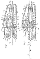
- An embodiment of the invention will now be described by way of example with reference to the accompanying drawings, in which:-
- Figures 1 and 2 are sectional elevations of a buckle with the tongue inserted and ejected respectively.
- Figure 3 is a plan view, of the mechanism of Figure 1 with the upper casing removed and with the tongue ejected,
- Figures 4 and 5 are transverse sections on lines IV-IV, V-V respectively of the buckle shown in Figures 1 and 2.
- The drawings show a
tongue 1 and abuckle 2, similar to those illustrated in our United Kingdom Patent Application No. 7900356 (GB-A-2030205). Thetongue 1 has ahead portion 3 with a pair oflatching shoulders head portion 3 is radiused to provide a nose for engaging a similarly radiused recess in an ejector member described below. - The
buckle 2 comprises ahousing 5 in which apush button 6 is slidably mounted for movement in the direction of thearrow 7. As seen in Figure 4, thehousing 5 is of a two-part construction which is secured along both sides by interengaging hookedportions housing 5 contains a pair offrame members mounting bracket portion 13 by arivet 11. Theframe members cutouts plates tongue 1. Theplates passageway 14 into which thetongue 1 can be inserted. As seen in Figures 4 and 5, thelower plate 12b has turned downportions latching member 20 from any crushing loads which may be applied to the buckle in service.Plate 12b also has laterally extendingportions 1 6a, 16b (Figures 3 and 4) which serve as guides for acamming member 21, as will be explained hereinafter. - An
ejector 17 has aradiused recess 18 for engaging the radiused edge of thehead portion 3 of thetongue 1. The rear portion of theejector 17 is formed by arectangular section portion 19, which projects into therespective cutouts plates ejector 17 longitudinally of thepassageway 14 when the tongue is inserted. Acircular section portion 22 with a chamfered edge serves to locate one end of acoil spring 23, the other end of which engages the ends of thecutouts - A
latching member 20 is in the form of a bridge having a pair of oppositely directedlateral shoulders latching member 20 is also provided with a pair of downwardly directedfeet 26a, 26b, the distance X therebetween (Figure 4) being slightly larger than the breadth of thehead portion 3 of thetongue 1. A pair of inwardly directedshoulders respective feet 26a, 26b. The distance Y (Figure 5) between theshoulders head portion 3 of thetongue 1 to engage with theradiused recess 18 of theejector 17. However, when thebridge 20 is in its latching position, theshoulders respective latching shoulders tongue 1 when fully inserted into the buckle. - In accordance with the present invention, abutments on the side face of the
ejector 17 are provided by forming agroove 28 in the surface thereof facing theframe member 12a, as can be seen in Figures 2 and 5. When thelatching member 20 is in its released position, the ends of theshoulders groove 28 with theircorners 29a and 29b projecting slightly into therecess 18. - A
spring member 30 is in the form of a flat plate with an aperture to receive therivet 11 which secures it to theupper frame member 12a. It also has a pair ofouter arms shoulders latching member 20 and to terminate in turned-up ends, only one of which, namely 32b, is seen in Figure 1. A pair ofinner arms latching member 20, one on each side of aprotuberance 34. Thesprings latching member 20 which acts substantially perpendicularly of the direction of insertion of thetongue 1 into the buckle. - The
camming member 21 is secured by arivet 37 to thepush button 6. The camming member extends over theupper plate 12a, adjacent the roof ofhousing 5 and downwardly, at each side, as shown in Figure 4. Thesides portions lower plate 12b. This enables thepush button 6 andcamming member 21 to be slidably guided in the direction of insertion of thetongue 1. Thecamming member 21 has a pair oframps push button 6, thecamming member 21 moves towards thelatching member 20 and thecamming surfaces 40a raise thelatching member 20 into arecess 41. This movement also loads theinner leaf springs latching member 20. It will also be noted from Figures 1 to 4, that the ends of thearms 31, 31 b pass beneath theshoulders latching member 20 and rest on thecamming surfaces 40a, 40b. This avoids friction between thecamming member 21 and thelatching member 20 which would otherwise lead to wear of the camming surfaces, if, as is convenient, camming member is made of plastics and latching member is made of steel. - A
return spring 45 is located in the housing so as to engagepart 43 of thecamming member 21 and to serve as a return spring for the push button andmember 21. - The entrance of
passageway 14 is bounded by amouthpiece 44 which also serves to locate the ends ofplates housing 5 is apertured so as to receive themounting bracket portion 13. - In operation, the
tongue 1 is inserted into thepassageway 14 with thebuckle 2 in the state shown in Figure 2 (Figure 2 also illustrates the ejection oftongue 1 by depressing thepush button 6 in the direction of the arrow). Thelatching member 20 is in a raised position, almost but not quite clear of the path of thetongue 1, because theshoulders groove 28 in the upper, forwardly extending surface of theejector 17. Initially, the. head portion of thetongue 1 engages with thecorners 29a, 29b on thelatching member 20 but, because these corners and the edges of thetongue 1 are radiused, the effect of continued insertion of the tongue is to lift thelatching member 20 out of thegroove 28 so that it rests on theejector 17 and thehead portion 2 of thetongue 1 engages therecessed portion 18 of theejector 17 and the ejector begins to move rearwardly against the bias ofspring 23. On further insertion, the head portion of the tongue passes beneath the lower edges ofshoulders latching member 20 is urged downwardly, by theleaf springs Spring 23 has been compressed and ia ready to eject the tongue when latchingmember 20 is next raised. - As shown in Figure 2, depression of the
push button 6 to move thecamming member 21 rearwardly results in the movement of latchingmember 20 into its raised position due to theramps outer arms shoulders latching member 20. Thearms latching shoulders latching shoulders tongue 1, the tongue is ejected by thespring 23. As the tongue slides beneath theshoulders ejector 17 follows in order to maintain thelatching member 20 in its raised position until it is received in therecess 18, in preparation for the next insertion of the tongue. - Because of the
groove 28, rearward movement of theejector 17 can only be initiated by an object which engages with bothcorners 29a and 29b simultaneously. If an attempt is made to depress theejector 17 with an object, such as a screwdriver, which engages with onlycorner 29a, 29b, thelatching member 20 will tilt leaving theshoulder groove 28.
Claims (3)
Applications Claiming Priority (3)
| Application Number | Priority Date | Filing Date | Title |
|---|---|---|---|
| DE19787828214U DE7828214U1 (en) | 1978-09-22 | 1978-09-22 | LATCH FOR CONNECTING SEAT BELTS |
| GB7924952 | 1979-07-18 | ||
| GB7924952 | 1979-07-18 |
Publications (2)
| Publication Number | Publication Date |
|---|---|
| EP0023122A1 EP0023122A1 (en) | 1981-01-28 |
| EP0023122B1 true EP0023122B1 (en) | 1983-05-18 |
Family
ID=25948263
Family Applications (2)
| Application Number | Title | Priority Date | Filing Date |
|---|---|---|---|
| EP79301883A Expired EP0009373B1 (en) | 1978-09-22 | 1979-09-13 | A tongue and buckle fastener for a safety belt harness |
| EP80302385A Expired EP0023122B1 (en) | 1978-09-22 | 1980-07-16 | A tongue and buckle fastener for a safety belt harness |
Family Applications Before (1)
| Application Number | Title | Priority Date | Filing Date |
|---|---|---|---|
| EP79301883A Expired EP0009373B1 (en) | 1978-09-22 | 1979-09-13 | A tongue and buckle fastener for a safety belt harness |
Country Status (6)
| Country | Link |
|---|---|
| US (2) | US4197619A (en) |
| EP (2) | EP0009373B1 (en) |
| JP (3) | JPS5542685A (en) |
| AU (2) | AU519206B2 (en) |
| FR (1) | FR2436579A1 (en) |
| GB (1) | GB2030205B (en) |
Families Citing this family (21)
| Publication number | Priority date | Publication date | Assignee | Title |
|---|---|---|---|---|
| FR2178731B1 (en) * | 1961-10-04 | 1975-03-21 | Ferodo Sa | |
| US4197619A (en) * | 1978-09-22 | 1980-04-15 | Britax (Wingard) Limited | Tongue and buckle fastener for a safety belt harness |
| FR2459016A1 (en) * | 1979-06-18 | 1981-01-09 | Stahl Carl Gmbh Co Kg | SEAT BELT CLASP |
| JPS6228883Y2 (en) * | 1980-01-23 | 1987-07-24 | ||
| DE3004150C2 (en) * | 1980-02-05 | 1984-10-31 | Repa Feinstanzwerk Gmbh, 7071 Alfdorf | Buckle for a seat belt |
| DE3004169C2 (en) | 1980-02-05 | 1986-07-03 | TRW Repa GmbH, 7077 Alfdorf | Buckle for seat belts |
| DE3006972C2 (en) * | 1980-02-25 | 1982-12-30 | Repa Feinstanzwerk Gmbh, 7071 Alfdorf | Buckle for seat belts |
| DE3324850A1 (en) * | 1983-07-09 | 1985-01-24 | Autoflug Gmbh, 2084 Rellingen | LOCK FOR SAFETY BELTS |
| DE3331453C2 (en) * | 1983-08-31 | 1987-04-23 | TRW Repa GmbH, 7077 Alfdorf | Buckle for a seat belt |
| DE3331435C2 (en) * | 1983-08-31 | 1985-10-31 | TRW Repa GmbH, 7071 Alfdorf | Assembly group consisting of a pushbutton and a functional part for a seat belt buckle |
| DE3331467C2 (en) * | 1983-08-31 | 1986-10-16 | TRW Repa GmbH, 7077 Alfdorf | Buckle for a seat belt |
| DE3337473A1 (en) * | 1983-10-14 | 1985-05-02 | TRW Repa GmbH, 7071 Alfdorf | BELT LOCK FOR A SAFETY BELT |
| US4576414A (en) * | 1984-01-27 | 1986-03-18 | Caterpiller Tractor Co. | Seat belt apparatus |
| US4614010A (en) * | 1985-06-03 | 1986-09-30 | Trw Inc. | Safety belt buckle |
| US4876772A (en) * | 1988-02-25 | 1989-10-31 | Indiana Mills & Manufacturing, Inc. | Safety belt buckle |
| US4942649A (en) * | 1988-02-25 | 1990-07-24 | Indiana Mills & Manufacturing, Inc. | Safety belt buckle |
| US5054171A (en) * | 1989-06-14 | 1991-10-08 | Kabushiki Kaisha Tokai-Rika-Denki-Seisakusho | Buckle device |
| DE4422224C2 (en) * | 1994-06-24 | 2003-06-26 | Opel Adam Ag | belt buckle |
| JP2000079004A (en) * | 1998-06-23 | 2000-03-21 | Tokai Rika Co Ltd | Buckle |
| US6430846B1 (en) * | 2001-07-13 | 2002-08-13 | Gnan-Jang Plastics Co., Ltd. | Shoe with detachable vamp |
| DE102021103334A1 (en) | 2021-02-12 | 2022-08-18 | Bayerische Motoren Werke Aktiengesellschaft | seat belt buckle unit |
Family Cites Families (23)
| Publication number | Priority date | Publication date | Assignee | Title |
|---|---|---|---|---|
| DE1002632B (en) * | 1953-11-23 | 1957-02-14 | Alfred Christensen Dipl Ing | Lock for parachute with central belt |
| FR2178731B1 (en) * | 1961-10-04 | 1975-03-21 | Ferodo Sa | |
| US3170211A (en) * | 1963-05-16 | 1965-02-23 | Kent Engineering Consultants | Safety seat buckle |
| US3349445A (en) * | 1966-02-21 | 1967-10-31 | Irving Air Chute Co Inc | Push button type safety seat belt buckle |
| US3522640A (en) * | 1969-11-21 | 1970-08-04 | Allied Chem | Mini buckle |
| US3656211A (en) * | 1970-04-28 | 1972-04-18 | Us Navy | Reciprocably latched canopy release |
| SE359448B (en) * | 1970-12-04 | 1973-09-03 | Lindblad S M | |
| DE2107666B2 (en) * | 1971-02-17 | 1977-05-18 | Klink, Wolf-Dieter, 7071 Lindach | PUSH BUTTON LOCKING BUCKLE |
| SE393742B (en) * | 1975-01-10 | 1977-05-23 | O L Lindblad | RECEIVER PART INCLUDED IN THE COUPLING DEVICE FOR A VEHICLE SAFETY BELT |
| US4000548A (en) * | 1976-03-04 | 1977-01-04 | Allied Chemical Corporation | Separable fastener with pin latch |
| US4096606A (en) * | 1976-03-04 | 1978-06-27 | Allied Chemical Corporation | Ferrule buckle with sliding release button |
| FR2349296A1 (en) * | 1976-04-28 | 1977-11-25 | Peugeot Aciers Et Outillage | Quick release safety belt coupling - has pivoting H-form bolt engaging strap tongue and engenders couple promoting release via secondary catch |
| SE400461B (en) * | 1976-07-19 | 1978-04-03 | Autoliv Ab | DEVICE FOR VEHICLE SAFETY BELTS |
| US4064603A (en) * | 1976-09-29 | 1977-12-27 | Gateway Industries, Inc. | Safety belt buckle |
| SE403428B (en) * | 1976-11-22 | 1978-08-21 | Lindblad Stig Martin | DEVICE AT THE SEAT BELT |
| GB1572106A (en) * | 1976-12-13 | 1980-07-23 | Wall Ltd Howard | Anchoring devices |
| SE422878B (en) * | 1977-03-30 | 1982-04-05 | Autoliv Ab | VEHICLE SEAL SEAT CLUTCH |
| DE2733767A1 (en) * | 1977-07-27 | 1979-02-15 | Autoflug Gmbh | PLUG FOR MOTOR VEHICLE SEAT BELT |
| DE2750133A1 (en) * | 1977-11-09 | 1979-05-10 | Kolb Gmbh & Co Hans | Car seat belt buckle - has push=in lug and acceptor housing with two spaced plates with locking pin |
| DE2803851B1 (en) * | 1978-01-30 | 1979-03-15 | Kolb Gmbh & Co Hans | Locking buckle for seat belts, especially motor vehicle seat belts |
| DE2828049A1 (en) * | 1978-06-26 | 1980-01-10 | Autoflug Gmbh | Vehicle safety belt lock - has button, tongue and housing, with sloping guide surface for sliding latch piece |
| DE7828214U1 (en) * | 1978-09-22 | 1979-01-04 | Britax (Wingard) Ltd., Chichester, Sussex (Grossbritannien) | LATCH FOR CONNECTING SEAT BELTS |
| US4197619A (en) * | 1978-09-22 | 1980-04-15 | Britax (Wingard) Limited | Tongue and buckle fastener for a safety belt harness |
-
1978
- 1978-12-13 US US05/969,049 patent/US4197619A/en not_active Expired - Lifetime
- 1978-12-18 JP JP15505078A patent/JPS5542685A/en active Granted
- 1978-12-18 AU AU42653/78A patent/AU519206B2/en not_active Expired
- 1978-12-18 FR FR7835605A patent/FR2436579A1/en active Granted
-
1979
- 1979-01-05 GB GB7900356A patent/GB2030205B/en not_active Expired
- 1979-09-13 EP EP79301883A patent/EP0009373B1/en not_active Expired
- 1979-09-20 JP JP12022079A patent/JPS5542699A/en active Pending
- 1979-09-21 AU AU51095/79A patent/AU521985B2/en not_active Ceased
-
1980
- 1980-07-16 EP EP80302385A patent/EP0023122B1/en not_active Expired
- 1980-07-16 US US06/169,243 patent/US4301576A/en not_active Expired - Lifetime
- 1980-07-16 JP JP9743280A patent/JPS5615701A/en active Granted
Also Published As
| Publication number | Publication date |
|---|---|
| FR2436579B1 (en) | 1984-02-10 |
| GB2030205B (en) | 1982-06-23 |
| AU5109579A (en) | 1980-03-27 |
| EP0009373A1 (en) | 1980-04-02 |
| FR2436579A1 (en) | 1980-04-18 |
| JPS5542685A (en) | 1980-03-26 |
| GB2030205A (en) | 1980-04-02 |
| AU519206B2 (en) | 1981-11-19 |
| JPS6345201B2 (en) | 1988-09-08 |
| AU521985B2 (en) | 1982-05-13 |
| AU4265378A (en) | 1980-03-27 |
| US4197619A (en) | 1980-04-15 |
| JPS6243682B2 (en) | 1987-09-16 |
| US4301576A (en) | 1981-11-24 |
| JPS5542699A (en) | 1980-03-26 |
| JPS5615701A (en) | 1981-02-16 |
| EP0009373B1 (en) | 1982-04-21 |
| EP0023122A1 (en) | 1981-01-28 |
Similar Documents
| Publication | Publication Date | Title |
|---|---|---|
| US4301576A (en) | Tongue and buckle fastener for a safety belt harness | |
| US5606783A (en) | Buckle for vehicle seat belt system | |
| US4733444A (en) | Seat belt buckle | |
| US4543693A (en) | Safety belt buckles | |
| EP0318031B1 (en) | Buckle device with switch for detecting tongue lock | |
| US4545097A (en) | Lock for a safety belt | |
| US4797984A (en) | Seat belt buckle | |
| CA1244639A (en) | Shaver with an auxiliary shear foil frame | |
| US6908322B1 (en) | Smart card connector carriage | |
| JPH0116416Y2 (en) | ||
| CA1052542A (en) | Buckles for vehicle safety belts | |
| US4367833A (en) | Tacker | |
| US4622727A (en) | Buckle for a safety belt | |
| US4391023A (en) | Buckle arrangement for seat belts | |
| JPS6345203B2 (en) | ||
| US4450604A (en) | Buckle for seat belt | |
| GB2104141A (en) | Seat belt buckle | |
| AU2004316797B2 (en) | Seat belt device | |
| GB2083542A (en) | A Tongue and Buckle Fastener for a Safety Belt | |
| US4393553A (en) | Locking device for a safety belt | |
| EP0205037B1 (en) | Safety belt buckle | |
| EP0043239A1 (en) | A tongue and buckle fastener for a safety belt | |
| US6014796A (en) | Seat belt buckle | |
| US4670952A (en) | Buckle apparatus | |
| JP3411407B2 (en) | buckle |
Legal Events
| Date | Code | Title | Description |
|---|---|---|---|
| PUAI | Public reference made under article 153(3) epc to a published international application that has entered the european phase |
Free format text: ORIGINAL CODE: 0009012 |
|
| AK | Designated contracting states |
Designated state(s): DE FR GB IT SE |
|
| 17P | Request for examination filed |
Effective date: 19810612 |
|
| ITF | It: translation for a ep patent filed | ||
| GRAA | (expected) grant |
Free format text: ORIGINAL CODE: 0009210 |
|
| AK | Designated contracting states |
Designated state(s): DE FR GB IT SE |
|
| ET | Fr: translation filed | ||
| REF | Corresponds to: |
Ref document number: 3063319 Country of ref document: DE Date of ref document: 19830707 |
|
| PLBE | No opposition filed within time limit |
Free format text: ORIGINAL CODE: 0009261 |
|
| STAA | Information on the status of an ep patent application or granted ep patent |
Free format text: STATUS: NO OPPOSITION FILED WITHIN TIME LIMIT |
|
| 26N | No opposition filed | ||
| REG | Reference to a national code |
Ref country code: GB Ref legal event code: 732 |
|
| ITTA | It: last paid annual fee | ||
| PGFP | Annual fee paid to national office [announced via postgrant information from national office to epo] |
Ref country code: SE Payment date: 19930715 Year of fee payment: 14 |
|
| PGFP | Annual fee paid to national office [announced via postgrant information from national office to epo] |
Ref country code: DE Payment date: 19930726 Year of fee payment: 14 |
|
| PG25 | Lapsed in a contracting state [announced via postgrant information from national office to epo] |
Ref country code: SE Effective date: 19940717 |
|
| EUG | Se: european patent has lapsed |
Ref document number: 80302385.2 Effective date: 19950210 |
|
| PG25 | Lapsed in a contracting state [announced via postgrant information from national office to epo] |
Ref country code: DE Effective date: 19950401 |
|
| EUG | Se: european patent has lapsed |
Ref document number: 80302385.2 |
|
| PGFP | Annual fee paid to national office [announced via postgrant information from national office to epo] |
Ref country code: GB Payment date: 19950705 Year of fee payment: 16 |
|
| PGFP | Annual fee paid to national office [announced via postgrant information from national office to epo] |
Ref country code: FR Payment date: 19950711 Year of fee payment: 16 |
|
| PG25 | Lapsed in a contracting state [announced via postgrant information from national office to epo] |
Ref country code: GB Effective date: 19960716 |
|
| GBPC | Gb: european patent ceased through non-payment of renewal fee |
Effective date: 19960716 |
|
| PG25 | Lapsed in a contracting state [announced via postgrant information from national office to epo] |
Ref country code: FR Effective date: 19970328 |
|
| REG | Reference to a national code |
Ref country code: FR Ref legal event code: ST |