EP0022939B1 - Liquid-liquid centrifugal contacting machine - Google Patents
Liquid-liquid centrifugal contacting machine Download PDFInfo
- Publication number
- EP0022939B1 EP0022939B1 EP80103575A EP80103575A EP0022939B1 EP 0022939 B1 EP0022939 B1 EP 0022939B1 EP 80103575 A EP80103575 A EP 80103575A EP 80103575 A EP80103575 A EP 80103575A EP 0022939 B1 EP0022939 B1 EP 0022939B1
- Authority
- EP
- European Patent Office
- Prior art keywords
- phase
- tray
- radially
- base wall
- rotor chamber
- Prior art date
- Legal status (The legal status is an assumption and is not a legal conclusion. Google has not performed a legal analysis and makes no representation as to the accuracy of the status listed.)
- Expired
Links
- 239000007788 liquid Substances 0.000 title description 36
- 230000004323 axial length Effects 0.000 claims description 11
- 238000005192 partition Methods 0.000 claims description 4
- 230000004888 barrier function Effects 0.000 claims 1
- 239000012530 fluid Substances 0.000 claims 1
- 239000012071 phase Substances 0.000 description 34
- 238000009826 distribution Methods 0.000 description 5
- 238000000034 method Methods 0.000 description 4
- 239000007791 liquid phase Substances 0.000 description 3
- 238000009827 uniform distribution Methods 0.000 description 3
- 230000000694 effects Effects 0.000 description 2
- 230000000712 assembly Effects 0.000 description 1
- 238000000429 assembly Methods 0.000 description 1
- 230000015572 biosynthetic process Effects 0.000 description 1
- 238000005352 clarification Methods 0.000 description 1
- 238000010276 construction Methods 0.000 description 1
- 230000007423 decrease Effects 0.000 description 1
- 230000003247 decreasing effect Effects 0.000 description 1
- 238000000605 extraction Methods 0.000 description 1
- 230000002093 peripheral effect Effects 0.000 description 1
- 230000000750 progressive effect Effects 0.000 description 1
- XLYOFNOQVPJJNP-UHFFFAOYSA-N water Substances O XLYOFNOQVPJJNP-UHFFFAOYSA-N 0.000 description 1
Images


Classifications
-
- B—PERFORMING OPERATIONS; TRANSPORTING
- B04—CENTRIFUGAL APPARATUS OR MACHINES FOR CARRYING-OUT PHYSICAL OR CHEMICAL PROCESSES
- B04B—CENTRIFUGES
- B04B5/00—Other centrifuges
- B04B5/06—Centrifugal counter-current apparatus
Definitions
- the centrifugal machine disclosed herein is generally of the type disclosed in U.S. patent 3,221,986 and French patent 1,425,631.
- a rotor shaft mounts a coaxial hollow casing with a plurality of concentric spaced annular sieves therein which have perforations for the concurrent passage of phases of heavy and light densities, the sieves defining a phase contacting volume within the rotor chamber.
- a light phase inlet passageway extends to the radially outer portion of the rotor chamber, and a heavy phase inlet passageway extends to the radially inner portion of the rotor chamber, to supply the phases to radially opposite sides of the phase contacting volume.
- the present invention solves the problem by providing special distributing trays with riser openings which are uniformly dispersed over the whole axial length of the tray to pass the phase not being distributed and, in addition, smaller perforations in the tray surrounding the riser openings over the whole axial length of the tray which pass only the phase being distributed.
- the distributer tray has perforations which are smaller than the perforations in the sieves which pass both phases in counterflow, and the total open area of the smaller openings in the distributor tray increases with the axial distance from the inlet passageway to achieve a uniform distribution of the phase being dispersed over the axial length of the tray.
- the system considers the diameter and number of the tray base openings and the diameter and radial extent of the riser openings which extend in a direction away from the phase contacting volume.
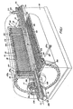
- the contactor includes a base 10 mounting one or more bearing assemblies 11 which journal a rotatable shaft generally designated 12.
- Mechanical seals generally designated 13 and 14 are provided at opposite ends of the shaft 12, which may be driven by a suitable electric motor via a belt 15 and a sheave 16.
- An end wall 17, a peripheral wall 18, and a detachable end wall 19 bolted (as at 20) to the flange 18a formed on wall 18, define a revolving contacting chamber generally designated 21.
- the light liquid e.g. oil
- the heavy liquid e.g. water
- the heavy liquid HL which is provided to the radially inner portion of the chamber 21, is centrifuged outward.
- the light liquid LL which is supplied to the radially outer portion of chamber 21, is thereby displaced inwardly. Tubes are utilized for separately supplying the light and heavy liquid to, and removing the heavy liquid from, the chamber 21 via the shaft 12.
- feed tubes 24 Provided to feed the heavy liquid HL into the radially inner portion of chamber 21 via coaxial bore 23 in shaft 12, are feed tubes 24.
- Feed tubes 25 feed light liquid LL to the radially outer portion of rotor chamber 21 via an axially concentric passage 26 provided in the opposite end of shaft 12. While in Figure 1 the tubes 24 and 25 are schematically depicted as in angular alignment, they actually are disposed out of angular alignment in the spoke-like arrangement demonstrated in Figure 2.
- exit tubes 27 which communicate with a concentric outer passage 28 in shaft 12 and an exit tube 29 connecting through seal 13.
- the light liquid LL is removed from the radially inner portion of the chamber 21, after it has moved radially through the chamber 21 from the outer portion thereof, via exits 30 and a concentric passage 32 provided in the opposite end of shaft 12 and communicating with an exit tube 33 connecting through the mechanical seal assembly 14.
- the exit tubes 29 may be angularly arranged in spokelike formation.
- slotted openings 34 are provided in tubes 24 near the inner ends thereof to permit the heavy liquid HL to be fed to the radially inner portion of chamber 21, and openings 35 are provided in the outer ends of tubes 25 to permit the light liquid LL to proceed through the feed tubes 25 to the radially outer portion of rotor chamber 21.
- the discharge tubes 27 for the heavy liquid have openings 27a to permit entrance of the heavy liquid HL thereto.
- the passageways for all of the tubes 24, 27, and 25 are threaded at their outer ends as at t to permit the threaded outer ends of these tubes to be threaded therein.
- the structure described thus far is conventional in countercurrent contacting and extraction apparatus and, in Figure 1, it will be noted that the drawing is shaded to represent clarification zones for each liquid where the perforation pattern in the sieves 22 changes to aid removal of the last traces of entrainment while, for purposes of illustration, only one screen 22 is shown outboard of tray 41, and only two screens 22 are shown inboard of tray 36, it is to be understood a greater number are contemplated in each instance.
- dispersing ducts of the general character utilized in U.S. patent 3,231,183, and having side wall openings are employed in commercial machines.
- tray 36 Provided to disperse the heavy liquid feed from tubes 24 is an annular open sided distributor tray 36, designated only by chain lines in Figure 3, but more particularly illustrated in Figures 5, 7, and 9.
- the tray 36 is provided with cylindrical perforations 37 in its base 38 and open ended risers 39 of considerably larger diameter.
- tray 36 has a flange 40 which abuts the end wall 17 or 19 and the tray 36 extends from one end of the rotor chamber 21 to the other.
- the riser openings 39 may be stated to face radially inwardly and Figure 5 indicates the relationship between the slotted openings 34 and the risers 39, it being observed that the openings 34 permit the inflow of liquid slightly radially inwardly of the base 38, and radially outwardly of the open ends of the risers 39.
- the distributor tray 41 for servicing the light liquid feed tubes 25, which is likewise designated only by a chain line in Figure 3, is identical in construction to the tray 36, except that its riser parts 39' face radially outwardly as indicated in Figure 4. As Figure 6 indicates like parts have been designated by primed numbers in Figure 6.
- Figure 8 is a fragmentary view which demonstrates that in each of the plates 36 and 41, where necessary, enlarged risers 42 are provided to pass the tubes 24, 25, and 27.
- the risers 39, 39', and 42 are of sufficient radial extent to permit a head to be developed to drive the phase through the distribution holes 37, or 37' respectively, over the axial length of the trays 36 and 41 with a linear velocity high enough to preclude counterflow of the other phase not being distributed.
- the portion of tray 36 shown is situated below shaft 12.
- the head of heavy liquid, as determined by the metered flow rate supply passages 23, is high enough to preclude counterflow of the light phase liquid proceeding in the counterflow direction to the larger riser openings 39 and 42.
- the unobstructed area of riser openings 39, 39' and 42 is the same.
- This differential head also provides the driving force for the. flow of the continuous or light liquid phase through the risers 39' and 42 in the opposite direction, and without counterflow of the heavy phase.
- the head decreases progressively axially outwardly from the openings 34, and 35 the head must be sufficient at the end walls 40 to provide for uniform axial distribution over the length of the trays 36 and 41 and the number of openings 37 and 37' can be gradually increased uniformly in a direction toward end walls 40, or their cross-sectional area can be gradually increased progressively in the direction toward end walls 40.
- the same progressive variance in number of openings or size is accomplished with the light phase distributor tray 41 with respect to the end walls 40.
- both the trays 36 and 41 are located radially so as to be within the countercurrent contact zone. This means the interfaces between the two phases on trays 36 and 41 are radially outboard and inboard respectively of exit openings 30 and 27a respectively.
- the tray (41) area is about twice the tray (36) area and the degree of perforation of tray 41 is about one fifth that of tray 36 for the same gallons per minute inflow.
- the smaller size openings for the phase to be dispersed should have a diameter typically around two to three millimeters and the open end risers should have a diameter typically in the range of eight to twenty-four millimeters.
- the height of the risers 39, 39', and 42 should typically be limited to about one to two percent of the outer diameter of the centrifugal contactor chamber 21.
- the head of liquid required for uniform distribution of the phase to be dispersed over the axial length of the dispersing zone or zones must be - less than the riser height provided.
- the minimum number of holes (37 or 37') for the dispersed phase in either of trays 36, 41 may be calculated according to the following formula where;
- the minimum number of risers required for passage of the continuous phase may be calculated according to the formula where:
- axial momentum effects tend to offset the axial head requirements required to cause the liquid to flow axially.
- uniform distribution can be achieved by providing an increasing number of holes per radial row which varies as the square root of the differential head. Alternately the actual spacing of rows can be decreased in proportion to the square root of the differential head.
- heavy liquid HL is supplied to the heavy liquid distribution tray 36 via openings 34, while simultaneously light liquid LL is supplied to the distribution tray 41 via tubes 25 and slotted openings 35.
- Heavy liquid HL collecting in the radially outer portion of the contactor adjacent wall 18 proceeds through openings 27a and discharge tubes 27 to the outlet tubes 29.
- the light liquid which collects adjacent the periphery of shaft 12 proceeds through the outlet openings 30 to the light liquid outlet 33. In the process, the heavy and light liquids are thoroughly contacted for whatever purpose the process contemplates.
Landscapes
- Extraction Or Liquid Replacement (AREA)
- Centrifugal Separators (AREA)
- Physical Or Chemical Processes And Apparatus (AREA)
Description
- The centrifugal machine disclosed herein is generally of the type disclosed in U.S. patent 3,221,986 and French patent 1,425,631. In both of these patents, a rotor shaft mounts a coaxial hollow casing with a plurality of concentric spaced annular sieves therein which have perforations for the concurrent passage of phases of heavy and light densities, the sieves defining a phase contacting volume within the rotor chamber. A light phase inlet passageway extends to the radially outer portion of the rotor chamber, and a heavy phase inlet passageway extends to the radially inner portion of the rotor chamber, to supply the phases to radially opposite sides of the phase contacting volume. In these prior art patents the supply of the heavy and light density phases to the boundaries of the phase contacting volume is effected in a non-uniform manner which particularly is unsatisfactory for casings of any considerable axial length in that the phase contacting will not be uniformly conducted over the axial length of the phase contacting volume.
- The present invention solves the problem by providing special distributing trays with riser openings which are uniformly dispersed over the whole axial length of the tray to pass the phase not being distributed and, in addition, smaller perforations in the tray surrounding the riser openings over the whole axial length of the tray which pass only the phase being distributed. The distributer tray has perforations which are smaller than the perforations in the sieves which pass both phases in counterflow, and the total open area of the smaller openings in the distributor tray increases with the axial distance from the inlet passageway to achieve a uniform distribution of the phase being dispersed over the axial length of the tray. The system considers the diameter and number of the tray base openings and the diameter and radial extent of the riser openings which extend in a direction away from the phase contacting volume.
- Figure 1 is a perspective elevational view of a somewhat schematic nature illustrating a contacting machine with a section thereof broken away to illustrate the manner in which light and heavy liquids are supplied to, and removed from, the apparatus;
- Figure 2 is a fragmentary, sectional elevational view more particularly illustrating the distributor trays in position in the machine;
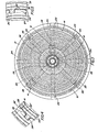
- Figure 3 is a transverse sectional view with chain lines schematically demonstrating the positions of the distributor trays;
- Figure 4 is a greatly enlarged view of the area indicated to be in section 4 in Figure 3;
- Figure 5 is a similar, greatly enlarged view of the area indicated to be in section 5 in Figure 3;
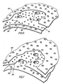
- Figure 6 is a considerably enlarged, fragmentary view of a distributor tray disposed between a pair of perforated plates;
- Figure 7 is a similar view showing a distributing tray for the other phase;
- Figure 8 is an enlarged fragmentary view of a portion of a distributor tray illustrating the manner in which the supply tubes extend up through enlarged risers in the tray; and
- Figure 9 is an enlarged fragmentary sectional view illustrating the manner in which the liquid head is utilized to drive the liquid being dispersed through the dispersing openings in a manner to avoid an inversion effect.
- Referring now more particularly to the accompanying drawings, and, in the first instance particularly to Figures 1, 2 and 3, the contactor includes a
base 10 mounting one or more bearing assemblies 11 which journal a rotatable shaft generally designated 12. Mechanical seals generally designated 13 and 14 are provided at opposite ends of theshaft 12, which may be driven by a suitable electric motor via abelt 15 and asheave 16. Anend wall 17, aperipheral wall 18, and adetachable end wall 19 bolted (as at 20) to the flange 18a formed onwall 18, define a revolving contacting chamber generally designated 21. - Provided in concentric relation within the
chamber 21, concentric withshaft 12, are a series of radially spaced concentric sieves or perforatedpartitions 22 which define multiple radially adjacent liquid phase contacting zones. Generally such contactors process immiscible liquid phases of different density. The light liquid (e.g. oil) is designated LL and the heavy liquid (e.g. water) is designated HL. As is well known, in this type of machine, the heavy liquid HL, which is provided to the radially inner portion of thechamber 21, is centrifuged outward. The light liquid LL, which is supplied to the radially outer portion ofchamber 21, is thereby displaced inwardly. Tubes are utilized for separately supplying the light and heavy liquid to, and removing the heavy liquid from, thechamber 21 via theshaft 12. - Provided to feed the heavy liquid HL into the radially inner portion of
chamber 21 viacoaxial bore 23 inshaft 12, arefeed tubes 24.Feed tubes 25 feed light liquid LL to the radially outer portion ofrotor chamber 21 via an axiallyconcentric passage 26 provided in the opposite end ofshaft 12. While in Figure 1 thetubes - Provided to remove heavy liquid HL from the radially outer portion of
chamber 21, after it has processed outwardly from the inner portion ofchamber 21, areexit tubes 27 which communicate with a concentricouter passage 28 inshaft 12 and anexit tube 29 connecting throughseal 13. The light liquid LL is removed from the radially inner portion of thechamber 21, after it has moved radially through thechamber 21 from the outer portion thereof, viaexits 30 and aconcentric passage 32 provided in the opposite end ofshaft 12 and communicating with anexit tube 33 connecting through the mechanical seal assembly 14. Theexit tubes 29 may be angularly arranged in spokelike formation. - As Figure 3 particularly indicates, slotted
openings 34 are provided intubes 24 near the inner ends thereof to permit the heavy liquid HL to be fed to the radially inner portion ofchamber 21, andopenings 35 are provided in the outer ends oftubes 25 to permit the light liquid LL to proceed through thefeed tubes 25 to the radially outer portion ofrotor chamber 21. - As Figure 2 indicates, the
discharge tubes 27 for the heavy liquid have openings 27a to permit entrance of the heavy liquid HL thereto. The passageways for all of thetubes sieves 22 changes to aid removal of the last traces of entrainment while, for purposes of illustration, only onescreen 22 is shown outboard oftray 41, and only twoscreens 22 are shown inboard oftray 36, it is to be understood a greater number are contemplated in each instance. Typically dispersing ducts of the general character utilized in U.S. patent 3,231,183, and having side wall openings, are employed in commercial machines. - What is considered to be novel in the present use is the method of distributing the flow of the liquids fed to the radially different portions of the chamber via the
feed tubes tubes 24 is an annular opensided distributor tray 36, designated only by chain lines in Figure 3, but more particularly illustrated in Figures 5, 7, and 9. Thetray 36 is provided withcylindrical perforations 37 in itsbase 38 and openended risers 39 of considerably larger diameter. At each end axially,tray 36 has aflange 40 which abuts theend wall tray 36 extends from one end of therotor chamber 21 to the other. In the case of the distributor tray 36, theriser openings 39 may be stated to face radially inwardly and Figure 5 indicates the relationship between theslotted openings 34 and therisers 39, it being observed that theopenings 34 permit the inflow of liquid slightly radially inwardly of thebase 38, and radially outwardly of the open ends of therisers 39. - The distributor tray 41 for servicing the light
liquid feed tubes 25, which is likewise designated only by a chain line in Figure 3, is identical in construction to thetray 36, except that its riser parts 39' face radially outwardly as indicated in Figure 4. As Figure 6 indicates like parts have been designated by primed numbers in Figure 6. - Figure 8 is a fragmentary view which demonstrates that in each of the
plates risers 42 are provided to pass thetubes risers distribution holes 37, or 37' respectively, over the axial length of thetrays - In the case of Figure 9, the portion of
tray 36 shown is situated belowshaft 12. The head of heavy liquid, as determined by the metered flowrate supply passages 23, is high enough to preclude counterflow of the light phase liquid proceeding in the counterflow direction to thelarger riser openings riser openings risers 39' and 42 in the opposite direction, and without counterflow of the heavy phase. Since the head decreases progressively axially outwardly from theopenings end walls 40 to provide for uniform axial distribution over the length of thetrays openings 37 and 37' can be gradually increased uniformly in a direction towardend walls 40, or their cross-sectional area can be gradually increased progressively in the direction towardend walls 40. The same progressive variance in number of openings or size is accomplished with the light phase distributor tray 41 with respect to theend walls 40. As Figure 3 indicates, both thetrays trays exit openings 30 and 27a respectively. - Since the light liquid enters at about twice the radial position of the heavy liquid, the head required for axial flow is about halved. The tray (41) area is about twice the tray (36) area and the degree of perforation of
tray 41 is about one fifth that oftray 36 for the same gallons per minute inflow. - In terms of further parameters the smaller size openings for the phase to be dispersed should have a diameter typically around two to three millimeters and the open end risers should have a diameter typically in the range of eight to twenty-four millimeters. The height of the
risers centrifugal contactor chamber 21. The head of liquid required for uniform distribution of the phase to be dispersed over the axial length of the dispersing zone or zones must be - less than the riser height provided. - The minimum number of holes (37 or 37') for the dispersed phase in either of
trays 
- Q=the volumetric flow rate of the dispersed phase
- W=the rotor speed in radians per second
- D=diameter of holes for dispersed phase
- h=height of risers
- R=radial position of feed tray
- p=density of heavy phase
- Ap=density difference between the phases
- It is preferable to provide a sufficient number of
holes 37 or 37' such that
- The minimum number of risers required for passage of the continuous phase may be calculated according to the formula

- Nd=the minimum number of
holes 37 or 37' - Qr=volumetric flow rate of the continuous phase
- Qd=volumetric flow rate of the dispersed phase
- dd=diameter of the
holes 37 or 37' for the dispersed phase - dc=diameter of the riser passages
- Once the phase to be dispersed has been introduced onto the distribution tray, axial momentum effects tend to offset the axial head requirements required to cause the liquid to flow axially. For more extreme axial lengths, when a significant head gradient is found to exist, uniform distribution can be achieved by providing an increasing number of holes per radial row which varies as the square root of the differential head. Alternately the actual spacing of rows can be decreased in proportion to the square root of the differential head.
- In operation, and as Figures 1 and 2 particularly indicate, heavy liquid HL is supplied to the heavy
liquid distribution tray 36 viaopenings 34, while simultaneously light liquid LL is supplied to thedistribution tray 41 viatubes 25 and slottedopenings 35. Heavy liquid HL collecting in the radially outer portion of the contactoradjacent wall 18 proceeds through openings 27a anddischarge tubes 27 to theoutlet tubes 29. The light liquid which collects adjacent the periphery ofshaft 12 proceeds through theoutlet openings 30 to the lightliquid outlet 33. In the process, the heavy and light liquids are thoroughly contacted for whatever purpose the process contemplates.
Claims (8)
Applications Claiming Priority (2)
| Application Number | Priority Date | Filing Date | Title |
|---|---|---|---|
| US06/057,420 US4284232A (en) | 1979-07-13 | 1979-07-13 | Liquid-liquid centrifugal contacting machines and methods of constructing and operating them |
| US57420 | 1998-04-08 |
Publications (2)
| Publication Number | Publication Date |
|---|---|
| EP0022939A1 EP0022939A1 (en) | 1981-01-28 |
| EP0022939B1 true EP0022939B1 (en) | 1984-01-18 |
Family
ID=22010480
Family Applications (1)
| Application Number | Title | Priority Date | Filing Date |
|---|---|---|---|
| EP80103575A Expired EP0022939B1 (en) | 1979-07-13 | 1980-06-24 | Liquid-liquid centrifugal contacting machine |
Country Status (5)
| Country | Link |
|---|---|
| US (1) | US4284232A (en) |
| EP (1) | EP0022939B1 (en) |
| JP (1) | JPS5653773A (en) |
| CA (1) | CA1135228A (en) |
| DE (1) | DE3066158D1 (en) |
Families Citing this family (2)
| Publication number | Priority date | Publication date | Assignee | Title |
|---|---|---|---|---|
| US5045046A (en) * | 1990-11-13 | 1991-09-03 | Bond Lesley O | Apparatus for oil separation and recovery |
| JP7391384B2 (en) * | 2018-01-22 | 2023-12-05 | サイノジー プロダクツ プロプライエタリー リミテッド | Fluid recovery systems, concentrators, and fluid recovery methods |
Family Cites Families (4)
| Publication number | Priority date | Publication date | Assignee | Title |
|---|---|---|---|---|
| US3179333A (en) * | 1961-06-13 | 1965-04-20 | Shell Oil Co | Centrifugal exchangers |
| US3221986A (en) * | 1961-06-13 | 1965-12-07 | Shell Oil Co | Centrifugal exchangers |
| US3327939A (en) * | 1965-11-15 | 1967-06-27 | Wladzia G P Doyle | Centrifugal countercurrent exchange device with improved removable strip means |
| FR1425631A (en) * | 1965-02-01 | 1966-01-24 | Dresser Ind | Contacting apparatus of the countercurrent centrifugal type with directed flow |
-
1979
- 1979-07-13 US US06/057,420 patent/US4284232A/en not_active Expired - Lifetime
-
1980
- 1980-06-18 CA CA000354309A patent/CA1135228A/en not_active Expired
- 1980-06-24 EP EP80103575A patent/EP0022939B1/en not_active Expired
- 1980-06-24 DE DE8080103575T patent/DE3066158D1/en not_active Expired
- 1980-07-11 JP JP9491880A patent/JPS5653773A/en active Granted
Also Published As
| Publication number | Publication date |
|---|---|
| EP0022939A1 (en) | 1981-01-28 |
| DE3066158D1 (en) | 1984-02-23 |
| JPS5758990B2 (en) | 1982-12-13 |
| JPS5653773A (en) | 1981-05-13 |
| US4284232A (en) | 1981-08-18 |
| CA1135228A (en) | 1982-11-09 |
Similar Documents
| Publication | Publication Date | Title |
|---|---|---|
| US4030897A (en) | Degassing of liquids | |
| KR0136369B1 (en) | Methods and equipment for removing solids and scattered solids from liquids | |
| JPS62102846A (en) | Inflow apparatus for centrifugal separator | |
| US3027390A (en) | Apparatus and method for centrifugal purification of fatty oils | |
| DE2427718C2 (en) | Centrifuge for separating liquids and solid particles | |
| EP0080311B1 (en) | Contacting device | |
| EP0048088A2 (en) | Centrifugal gas-liquid contact apparatus | |
| US2758784A (en) | Centrifugal countercurrent exchange device | |
| EP1068016B1 (en) | Rotor for centrifugal separator | |
| US2665196A (en) | Multistage internal mixer-settler extraction apparatus | |
| FI57059B (en) | EXTRAKTIONSENHET FOER VAETSKE-VAETSKEEXTRAKTION | |
| US4284232A (en) | Liquid-liquid centrifugal contacting machines and methods of constructing and operating them | |
| FI59037B (en) | KONTINUERLIGT ARBETANDE CENTRIFUG | |
| US4225079A (en) | Liquid-liquid centrifugal extractor | |
| US2335339A (en) | Foam homogenizer | |
| US3202347A (en) | Countercurrent flow centrifugal separator | |
| US3179333A (en) | Centrifugal exchangers | |
| US2941871A (en) | Horizontal counter-current liquid extractor | |
| DE2745248B2 (en) | Device for the continuous separation of foams into their liquid and gaseous components | |
| SE455623B (en) | KIT AND DEVICE FOR LOWERING THE PRESSURE IN A LIQUID MIXTURE | |
| US3108953A (en) | Apparatus for contacting two fluids with each other countercurrently | |
| US3385447A (en) | Centrifugal separator | |
| SU1269847A1 (en) | Centrifugal apparatus for purifying liquid | |
| US2641363A (en) | Apparatus for clarifying liquids | |
| US3114706A (en) | Centrifugal countercurrent exchange device with interchangeable disc columns |
Legal Events
| Date | Code | Title | Description |
|---|---|---|---|
| PUAI | Public reference made under article 153(3) epc to a published international application that has entered the european phase |
Free format text: ORIGINAL CODE: 0009012 |
|
| AK | Designated contracting states |
Designated state(s): CH DE FR GB SE |
|
| 17P | Request for examination filed |
Effective date: 19810713 |
|
| GRAA | (expected) grant |
Free format text: ORIGINAL CODE: 0009210 |
|
| AK | Designated contracting states |
Designated state(s): CH DE FR GB LI SE |
|
| REF | Corresponds to: |
Ref document number: 3066158 Country of ref document: DE Date of ref document: 19840223 |
|
| ET | Fr: translation filed | ||
| PGFP | Annual fee paid to national office [announced via postgrant information from national office to epo] |
Ref country code: CH Payment date: 19840521 Year of fee payment: 5 |
|
| PGFP | Annual fee paid to national office [announced via postgrant information from national office to epo] |
Ref country code: FR Payment date: 19840615 Year of fee payment: 5 |
|
| PGFP | Annual fee paid to national office [announced via postgrant information from national office to epo] |
Ref country code: SE Payment date: 19840630 Year of fee payment: 5 |
|
| PGFP | Annual fee paid to national office [announced via postgrant information from national office to epo] |
Ref country code: DE Payment date: 19840829 Year of fee payment: 5 |
|
| PLBE | No opposition filed within time limit |
Free format text: ORIGINAL CODE: 0009261 |
|
| STAA | Information on the status of an ep patent application or granted ep patent |
Free format text: STATUS: NO OPPOSITION FILED WITHIN TIME LIMIT |
|
| 26N | No opposition filed | ||
| PG25 | Lapsed in a contracting state [announced via postgrant information from national office to epo] |
Ref country code: GB Effective date: 19880624 |
|
| PG25 | Lapsed in a contracting state [announced via postgrant information from national office to epo] |
Ref country code: SE Effective date: 19880625 |
|
| PG25 | Lapsed in a contracting state [announced via postgrant information from national office to epo] |
Ref country code: LI Effective date: 19880630 Ref country code: CH Effective date: 19880630 |
|
| GBPC | Gb: european patent ceased through non-payment of renewal fee | ||
| PG25 | Lapsed in a contracting state [announced via postgrant information from national office to epo] |
Ref country code: FR Free format text: LAPSE BECAUSE OF NON-PAYMENT OF DUE FEES Effective date: 19890228 |
|
| REG | Reference to a national code |
Ref country code: CH Ref legal event code: PL |
|
| PG25 | Lapsed in a contracting state [announced via postgrant information from national office to epo] |
Ref country code: DE Effective date: 19890301 |
|
| REG | Reference to a national code |
Ref country code: FR Ref legal event code: ST |
|
| EUG | Se: european patent has lapsed |
Ref document number: 80103575.9 Effective date: 19890220 |