EP0022820B1 - Three dimensional television system - Google Patents
Three dimensional television system Download PDFInfo
- Publication number
- EP0022820B1 EP0022820B1 EP80900211A EP80900211A EP0022820B1 EP 0022820 B1 EP0022820 B1 EP 0022820B1 EP 80900211 A EP80900211 A EP 80900211A EP 80900211 A EP80900211 A EP 80900211A EP 0022820 B1 EP0022820 B1 EP 0022820B1
- Authority
- EP
- European Patent Office
- Prior art keywords
- field
- past
- image
- video signal
- chrominance
- Prior art date
- Legal status (The legal status is an assumption and is not a legal conclusion. Google has not performed a legal analysis and makes no representation as to the accuracy of the status listed.)
- Expired
Links
- 230000000295 complement effect Effects 0.000 claims abstract description 12
- 239000011521 glass Substances 0.000 claims abstract description 11
- 239000000872 buffer Substances 0.000 claims description 10
- 238000000034 method Methods 0.000 claims description 10
- 239000002131 composite material Substances 0.000 claims description 8
- 238000005070 sampling Methods 0.000 claims 1
- 239000003086 colorant Substances 0.000 abstract description 3
- 238000006073 displacement reaction Methods 0.000 abstract description 2
- 230000000694 effects Effects 0.000 description 14
- 230000003111 delayed effect Effects 0.000 description 3
- 238000012986 modification Methods 0.000 description 3
- 230000004048 modification Effects 0.000 description 3
- 238000012545 processing Methods 0.000 description 3
- 230000003304 psychophysiological effect Effects 0.000 description 3
- 238000010586 diagram Methods 0.000 description 2
- 238000004519 manufacturing process Methods 0.000 description 2
- 238000000926 separation method Methods 0.000 description 2
- 238000001914 filtration Methods 0.000 description 1
- 238000012544 monitoring process Methods 0.000 description 1
- 230000000135 prohibitive effect Effects 0.000 description 1
- 230000000979 retarding effect Effects 0.000 description 1
- 239000007787 solid Substances 0.000 description 1
- 238000012546 transfer Methods 0.000 description 1
Images
Classifications
-
- H—ELECTRICITY
- H04—ELECTRIC COMMUNICATION TECHNIQUE
- H04N—PICTORIAL COMMUNICATION, e.g. TELEVISION
- H04N13/00—Stereoscopic video systems; Multi-view video systems; Details thereof
- H04N13/20—Image signal generators
- H04N13/261—Image signal generators with monoscopic-to-stereoscopic image conversion
-
- H—ELECTRICITY
- H04—ELECTRIC COMMUNICATION TECHNIQUE
- H04N—PICTORIAL COMMUNICATION, e.g. TELEVISION
- H04N13/00—Stereoscopic video systems; Multi-view video systems; Details thereof
- H04N13/20—Image signal generators
- H04N13/257—Colour aspects
-
- H—ELECTRICITY
- H04—ELECTRIC COMMUNICATION TECHNIQUE
- H04N—PICTORIAL COMMUNICATION, e.g. TELEVISION
- H04N13/00—Stereoscopic video systems; Multi-view video systems; Details thereof
- H04N13/20—Image signal generators
- H04N13/296—Synchronisation thereof; Control thereof
-
- H—ELECTRICITY
- H04—ELECTRIC COMMUNICATION TECHNIQUE
- H04N—PICTORIAL COMMUNICATION, e.g. TELEVISION
- H04N13/00—Stereoscopic video systems; Multi-view video systems; Details thereof
- H04N13/30—Image reproducers
- H04N13/324—Colour aspects
-
- H—ELECTRICITY
- H04—ELECTRIC COMMUNICATION TECHNIQUE
- H04N—PICTORIAL COMMUNICATION, e.g. TELEVISION
- H04N13/00—Stereoscopic video systems; Multi-view video systems; Details thereof
- H04N13/30—Image reproducers
- H04N13/332—Displays for viewing with the aid of special glasses or head-mounted displays [HMD]
- H04N13/334—Displays for viewing with the aid of special glasses or head-mounted displays [HMD] using spectral multiplexing
-
- H—ELECTRICITY
- H04—ELECTRIC COMMUNICATION TECHNIQUE
- H04N—PICTORIAL COMMUNICATION, e.g. TELEVISION
- H04N13/00—Stereoscopic video systems; Multi-view video systems; Details thereof
- H04N13/10—Processing, recording or transmission of stereoscopic or multi-view image signals
- H04N13/106—Processing image signals
- H04N13/15—Processing image signals for colour aspects of image signals
-
- H—ELECTRICITY
- H04—ELECTRIC COMMUNICATION TECHNIQUE
- H04N—PICTORIAL COMMUNICATION, e.g. TELEVISION
- H04N13/00—Stereoscopic video systems; Multi-view video systems; Details thereof
- H04N13/10—Processing, recording or transmission of stereoscopic or multi-view image signals
- H04N13/106—Processing image signals
- H04N13/158—Switching image signals
-
- H—ELECTRICITY
- H04—ELECTRIC COMMUNICATION TECHNIQUE
- H04N—PICTORIAL COMMUNICATION, e.g. TELEVISION
- H04N13/00—Stereoscopic video systems; Multi-view video systems; Details thereof
- H04N13/10—Processing, recording or transmission of stereoscopic or multi-view image signals
- H04N13/106—Processing image signals
- H04N13/167—Synchronising or controlling image signals
-
- H—ELECTRICITY
- H04—ELECTRIC COMMUNICATION TECHNIQUE
- H04N—PICTORIAL COMMUNICATION, e.g. TELEVISION
- H04N13/00—Stereoscopic video systems; Multi-view video systems; Details thereof
- H04N13/10—Processing, recording or transmission of stereoscopic or multi-view image signals
- H04N13/189—Recording image signals; Reproducing recorded image signals
-
- H—ELECTRICITY
- H04—ELECTRIC COMMUNICATION TECHNIQUE
- H04N—PICTORIAL COMMUNICATION, e.g. TELEVISION
- H04N13/00—Stereoscopic video systems; Multi-view video systems; Details thereof
- H04N13/10—Processing, recording or transmission of stereoscopic or multi-view image signals
- H04N13/194—Transmission of image signals
-
- H—ELECTRICITY
- H04—ELECTRIC COMMUNICATION TECHNIQUE
- H04N—PICTORIAL COMMUNICATION, e.g. TELEVISION
- H04N19/00—Methods or arrangements for coding, decoding, compressing or decompressing digital video signals
- H04N19/50—Methods or arrangements for coding, decoding, compressing or decompressing digital video signals using predictive coding
- H04N19/597—Methods or arrangements for coding, decoding, compressing or decompressing digital video signals using predictive coding specially adapted for multi-view video sequence encoding
Definitions
- This invention relates to video signal processing. More specifically, this invention concerns real time processing of video signals for the purpose of creating a three dimensional effect.
- Three dimensional or stereoscopic viewing generally requires the production of disparate left and right images.
- Most conventional three dimensional techniques produce images which are not compatible, i.e. which cannot be viewed comfortably without specially filtered glasses.
- Songer U.S. Patent No. 3,712,199
- an anaglyph i.e. color encoded
- the image is compatible in that when it is viewed without the specially filtered glasses required for-stereoscopy, it is seen as an acceptable two-dimensional image.
- image separation (sometimes referred to as binocular disparity) is created by a color fringing effect on the out-of-focus objects.
- objects fore of the plane of focus may be imaged with a magenta defocus blur on the left side and a cyan defocus blur on the right side.
- Objects aft of the plane of focus will be encoded in the opposite sense, i.e. cyan on the left and magenta on the right.
- a process in accordance with the generic clause of claim 1 is already known from US-A-2 865 988.
- This prior art reference discloses how to provide a three-dimensional effect based on the motion of a moving element with respect to the background of the moving element including the comparing of past and current fields or frames.
- a conventional video signal is transmitted to a television receiver which is suitably modified and converts the conventional video signal to a stereoscopic signal.
- a first drawback of this prior art process consists in that the receiver has to be modified in order to convert the conventional video signal into a stereoscopic signal. This modification causes high costs and therefore, lacks in practical usability. Futhermore, this known process is incapable of providing a "full colour" image since each frame is produced in only a single colour. As the system uses the polarizing technique, another drawback is that the images are displayed sequentially and not concurrently.
- the main object of this invention is to provide a practical apparatus and method for processing standard video signals so as to enable compatible three dimensional television using standard television receivers.
- the present invention requires no modification of existing lens systems and can produce compatible three dimensional images regardless of the depth of focus of the taking lens.
- the invention can be used to process prerecorded video signals to produce compatible stereoscopic images.
- a three dimensional effect requires that there be movement of at least one object in the scene being viewed.
- One of the chrominance components of the video signal corresponding to a preselected past field is combined with the complementary chrominance component of the current field in such a way as to produce disparate color encoded images, preferably in the background, due to the object movement.
- the disparate images are blurred slightly but not so much as to be objectionable.
- the image disparity produces a realistic three dimensional effect.
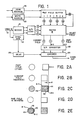
- a conventional incoming color video signal (from a camera or recorder) appears on line 10. This signal is fed to a sync generator 12 and a decoder 14. The sync generator 12 produces the timing signals for the system which therefore is locked to the incoming video. Decoder 14 separates the video signal into its luminance (Y) and chrominance (R-Y and B-Y) components. As is well known, all of the required color information is contained in these complementary R-Y (magenta) and B-Y (cyan) components.
- the decoder outputs are coupled to an analog-to-digital converter 16 which samples the three components and converts each sample to a discrete digital value.
- each analog signal may be sampled at four times the NTSC subcarrier frequency (e.g. about 15 MHz) with the luminance samples converted into eight bit words and the chrominance samples into four bit words. This is indicated in Figure 1 by the numerals "8" and "4" placed within circles at the outputs of analog-to-digital converter 16.
- the sync generator 12, decoder 14 and analog-to-digital converter 16 may be conventional, commercially available devices.
- binocular disparity is created by the change in position, from field to field, which exists in the case of an object moving in the scene being viewed (in the United States, a field includes 262.5 horizontal lines; a raster consists of two interlaced fields).
- Figures 2A-2E The way in which the invention produces a three dimensional effect is explained with reference to Figures 2A-2E.
- Figures 2A and 2B may be considered to represent successive fields, with Figure 2A representing a "past” field and Figure 2B representing the "current" field.
- Figure 2B shows the image of the past field shifted left the distance "d" so that the moving squares of the past and current fields are in exact registry and the stationary circles are out of registry. If these images are color encoded as described above and combined, the composite image of Figure 2E results. In this composite image, the entire moving square is in full color whereas the stationary circle includes a central full colored core 46 with magenta and cyan fringes 48 and 50, respectively. Since the same binocular disparity exists in Figure 2 as in Figure 2C, the same psychophysiological 3-D effect is achieved but compatability is enhanced since the principal object of interest (the moving square) no longer includes the requisite color fringes.
- the system shown in Figure 1 produces the past and current fields corresponding to Figures 2A and 2B, shifts the past field so that the moving objects of the two fields are in registry, and then combines complementary chrominance components of the two fields to produce a composite color encoded field corresponding to Figure 2E.
- the color fringes are transferred from the moving object to the stationary object.
- the digital signals from converter 16 are fed to a switching network 18.
- Switch 18 routes the digital signals throughout the system and will be computer controlled.
- the digital signals corresponding to the last four fields of the original television picture are routed to a past field buffer 20 for temporary storage so that the operator can change the image disparity (for example, depending on the object speed) between the current field and the selected field.
- each of the past field buffers 20 is returned to the switching network 18.
- the switch 18 selects the luminance component and one of the chrominance components (e.g. R-Y) of the current field and couples these signals. to two inputs of a digital-to-analog converter 22.
- the complementary chrominance component (e.g. R-Y) of the selected past field is coupled through switch 18 to a third input of digital-to-analog converter 22 which then produces three video signals corresponding, respectively, to the luminance and R-Y chrominance component of the current field and the B-Y chrominance component of the selected past field.
- the three outputs of the converter 22 are combined in an encoder 24 which also adds the appropriate timing signals from the sync generator 12, suitably delayed by a delay-fine 25 to compensate for the operation of the system as described.
- the operation of the past field buffers 20 is under control of a read address circuit 26 and a write address circuit 28. In a well-known manner, these devices select starting addresses for the reading and writing operations and enable the selected data to be written in or read from memory.
- the video signal of the encoder 24 would produce the type of image shown in Figure 2C, i.e. with a color fringe on the moving objects only.
- the arrangement shown in Figure 1 enables the moving object(s) of the selected past and current fields to be brought into registration by retarding or advancing the starting address of the read address counter 26.
- the read address circuit 26 would advance the read-out of the selected past field buffer 20 to thereby shift the image on the screen to the left.
- the effect is to move the color fringing to the stationary objects which are usually in the background.
- Registration of the moving objects may be manual or automatic. If manual, the operator will monitor the video image and adjust the starting address of the read address circuit 26 so that the moving object includes no color fringe (i.e. the moving objects of the past and current fields are in registry). Continuous monitoring will not normally be required if the moving objects move at an approximately constant rate.
- the computer may be programmed to compare the relative moving object position and adjust the read address circuit 26 accordingly.
- Each of the past field buffers 20 stores a digital representation of a single video field. This may comprise 263 horizontal lines of 390 "dots" each. As noted previously each "dot” includes light luminance bits and form bits for each of the two chrominance components (R-Y and B-Y). This enables the production of sixty- four different colors and/or shades of gray.
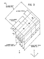
- Figure 3 shows diagrammatically a three-dimensional switching network which can be used to route the signals to the various locations shown in Figure 1.
- the inputs and outputs in Figure 3 are labeled to correspond to Figure 1 with many individual input lines being omitted for the purposes of clarity.
- the 16-line input from each of the four past field buffers 20 is represented by only a single input line or (in the case of buffer No. 1) by the first and last lines.
- control lines 50-55 For purposes of the switching operation as shown in Figure 1, six separate control lines 50-55 are shown.
- the application of a control voltage to line 50 couples to 16-bit current field signal (from the analog-to-digital converter 16) to the past field buffers 20.
- Application of a control signal to line 51 couples the luminance and R-Y chrominance component of the current field to the digital-to-analog converter 22.
- Application of a control signal to any of lines 52, 53, 54 or 55 will couple the complementary chrominance component (B-Y) of the selected past field (depending on which of the control lines is energized) to the third input of converter 22.
- B-Y complementary chrominance component
- the switch may be considered to be broken up into three separate sections 18A, 18B and 18C.
- Section 18A switches all of the luminance information whereas the chrominance components are switched by the sections 18B (R-Y) and 18C (B-Y).
Landscapes
- Engineering & Computer Science (AREA)
- Multimedia (AREA)
- Signal Processing (AREA)
- Physics & Mathematics (AREA)
- Spectroscopy & Molecular Physics (AREA)
- Color Television Systems (AREA)
- Testing, Inspecting, Measuring Of Stereoscopic Televisions And Televisions (AREA)
- Processing Of Color Television Signals (AREA)
Abstract
Description
- This invention relates to video signal processing. More specifically, this invention concerns real time processing of video signals for the purpose of creating a three dimensional effect.
- Three dimensional or stereoscopic viewing generally requires the production of disparate left and right images. Most conventional three dimensional techniques produce images which are not compatible, i.e. which cannot be viewed comfortably without specially filtered glasses. Songer (U.S. Patent No. 3,712,199) has disclosed an anaglyph (i.e. color encoded) stereoscopic system capable of producing a compatible three dimensional image. The image is compatible in that when it is viewed without the specially filtered glasses required for-stereoscopy, it is seen as an acceptable two-dimensional image.
- In Songer, image separation (sometimes referred to as binocular disparity) is created by a color fringing effect on the out-of-focus objects. For example, objects fore of the plane of focus may be imaged with a magenta defocus blur on the left side and a cyan defocus blur on the right side. Objects aft of the plane of focus will be encoded in the opposite sense, i.e. cyan on the left and magenta on the right. When viewed through appropriately filtered glasses, disparate out of focus images are seen causing the viewer to perceive what is termed by Songer as "psychophysiological 3-D". Without the glasses, the defocus blurs are barely noticeable and the image is perceived is a normal two dimensional picture.
- Although Songer's system is applicable to television, it has certain drawbacks which limits its applicability to this medium. In the first place, since image disparity is created by a defocus blur, a lens system with very low depth of focus (e.g. telephoto lenses) will not produce sufficient color fringing to create a three dimensional effect. Such lenses are frequently used for television, particularly for sporting events.
- Secondly, the cost involved in modifying existing television cameras in accordance with the Songer system is prohibitive.
- A process in accordance with the generic clause of
claim 1 is already known from US-A-2 865 988. This prior art reference discloses how to provide a three-dimensional effect based on the motion of a moving element with respect to the background of the moving element including the comparing of past and current fields or frames. A conventional video signal is transmitted to a television receiver which is suitably modified and converts the conventional video signal to a stereoscopic signal. - In accordance with this prior art arrangement, there is presented on the screen of the picture tube a sequence of adjacent frame elements having one undelayed picture frame portion and one delayed frame portion. The electronic switch is controlled by the first pulse of every second field sync signal of the television signal. Hence, the even frame portions of the received signal are omitted and replaced by a delayed odd picture frame portion. A light filtering assembly controlled by the signal which is fed to the electronic switch arrangement presents the first picture frame polarized in one sense and the second picture frame polarized in the opposite sense. Hence, an observer having polarizing glasses realises the first picture frame with one eye and the second with the other. Consequently, objects moving with respect to the camera will appear as three-dimensional objects, since there is a lateral displacement between the image of this object as seen from one eye and the image of this object as seen by the other eye. A first drawback of this prior art process consists in that the receiver has to be modified in order to convert the conventional video signal into a stereoscopic signal. This modification causes high costs and therefore, lacks in practical usability. Futhermore, this known process is incapable of providing a "full colour" image since each frame is produced in only a single colour. As the system uses the polarizing technique, another drawback is that the images are displayed sequentially and not concurrently.
- The main object of this invention is to provide a practical apparatus and method for processing standard video signals so as to enable compatible three dimensional television using standard television receivers.
- The present invention requires no modification of existing lens systems and can produce compatible three dimensional images regardless of the depth of focus of the taking lens.
- Because the illusion of depth, in accordance with the invention, is based on object movement, the invention can be used to process prerecorded video signals to produce compatible stereoscopic images.
- In accordance with an embodiment of the invention, a three dimensional effect requires that there be movement of at least one object in the scene being viewed. One of the chrominance components of the video signal corresponding to a preselected past field is combined with the complementary chrominance component of the current field in such a way as to produce disparate color encoded images, preferably in the background, due to the object movement. When viewed normally, the disparate images are blurred slightly but not so much as to be objectionable. When viewed through appropriately filtered glasses, the image disparity produces a realistic three dimensional effect.
- The invention is described in detail below with reference to the attached drawings, wherein:
- Figure 1 is a block diagram of the invention;
- Figure 2 is an explanatory diagram showing how binocular disparity is created in accordance with the invention; and
- Figure 3 is a schematic illustration of a preferred switching network for use with the invention.
- In Figure 1, a conventional incoming color video signal (from a camera or recorder) appears on line 10. This signal is fed to a sync generator 12 and a
decoder 14. The sync generator 12 produces the timing signals for the system which therefore is locked to the incoming video.Decoder 14 separates the video signal into its luminance (Y) and chrominance (R-Y and B-Y) components. As is well known, all of the required color information is contained in these complementary R-Y (magenta) and B-Y (cyan) components. - The decoder outputs are coupled to an analog-to-
digital converter 16 which samples the three components and converts each sample to a discrete digital value. For example, each analog signal may be sampled at four times the NTSC subcarrier frequency (e.g. about 15 MHz) with the luminance samples converted into eight bit words and the chrominance samples into four bit words. This is indicated in Figure 1 by the numerals "8" and "4" placed within circles at the outputs of analog-to-digital converter 16. - The sync generator 12,
decoder 14 and analog-to-digital converter 16 may be conventional, commercially available devices. - The illusion of depth requires binocular disparity. That is, the left eye must see an image displaced slightly from the image seen by the right eye. In accordance with the invention, binocular disparity is created by the change in position, from field to field, which exists in the case of an object moving in the scene being viewed (in the United States, a field includes 262.5 horizontal lines; a raster consists of two interlaced fields).
- The way in which the invention produces a three dimensional effect is explained with reference to Figures 2A-2E. Consider a scene consisting of a circle and a square (Figure 2A), with the square being movable toward the circle. Assume also that the square moves at a rate such that from field to field it moves the distance "d". In this case, Figures 2A and 2B may be considered to represent successive fields, with Figure 2A representing a "past" field and Figure 2B representing the "current" field.
- Because of the movement of the square, the relative position of the square changes from the past to the current field. Consequently, if the two fields are encoded in complementary colors (e.g. cyan and magenta), by combining the two fields a color fringing effect of the type disclosed by Songer can be achieved. Thus, consider the past field of Figure 2A to be magenta (corresponding, for example, to the R-Y chrominance component) and the current field of Figure 2B to be cyan (B-Y). If these two fields are combined as shown in Figure 2C, the circle (which has not be displaced) will include both cyan and magenta images in full registry and will therefore appear in its proper color. The square, however, which has been displaced by the distance "d" will consist of a
central portion 40 including both cyan and magenta together with amagenta fringe 42 and acyan fringe 44. - If the composite image of Figure 2C is viewed through magenta/cyan glasses, the disparity in position of the square appears as though it were a tr.ue binocular disparity and the viewer will perceive the same psychophysiological 3-D effect as in the Songer system.
- Although a three dimensional effect can be achieved by combining the two fields of Figures 2A and 2B, the addition of the color fringes to the moving object is objectionable since the moving object is normally the major object of interest. For compatibility it is preferable that the major object of interest (corresponding to the in-focus object in Songer) consist of the registered image components with the stationary objects (usually in the background) including the color fringes. This effect can be achieved by registering the moving objects of successive fields as explained with reference to Figures 2D and 2E.
- Figure 2B shows the image of the past field shifted left the distance "d" so that the moving squares of the past and current fields are in exact registry and the stationary circles are out of registry. If these images are color encoded as described above and combined, the composite image of Figure 2E results. In this composite image, the entire moving square is in full color whereas the stationary circle includes a central full
colored core 46 with magenta andcyan fringes - As described below, the system shown in Figure 1 produces the past and current fields corresponding to Figures 2A and 2B, shifts the past field so that the moving objects of the two fields are in registry, and then combines complementary chrominance components of the two fields to produce a composite color encoded field corresponding to Figure 2E. In effect, the color fringes are transferred from the moving object to the stationary object.
- To transfer the color fringes, in accordance with a preferred embodiment of the invention, the digital signals from
converter 16 are fed to aswitching network 18.Switch 18 routes the digital signals throughout the system and will be computer controlled. The digital signals corresponding to the last four fields of the original television picture are routed to apast field buffer 20 for temporary storage so that the operator can change the image disparity (for example, depending on the object speed) between the current field and the selected field. - The output of each of the past field buffers 20 is returned to the
switching network 18. Theswitch 18, as explained in further detail below, selects the luminance component and one of the chrominance components (e.g. R-Y) of the current field and couples these signals. to two inputs of a digital-to-analog converter 22. The complementary chrominance component (e.g. R-Y) of the selected past field is coupled throughswitch 18 to a third input of digital-to-analog converter 22 which then produces three video signals corresponding, respectively, to the luminance and R-Y chrominance component of the current field and the B-Y chrominance component of the selected past field. - The three outputs of the
converter 22 are combined in anencoder 24 which also adds the appropriate timing signals from the sync generator 12, suitably delayed by a delay-fine 25 to compensate for the operation of the system as described. - The operation of the past field buffers 20 is under control of a
read address circuit 26 and awrite address circuit 28. In a well-known manner, these devices select starting addresses for the reading and writing operations and enable the selected data to be written in or read from memory. - Without further modification, the video signal of the
encoder 24 would produce the type of image shown in Figure 2C, i.e. with a color fringe on the moving objects only. However, the arrangement shown in Figure 1 enables the moving object(s) of the selected past and current fields to be brought into registration by retarding or advancing the starting address of the readaddress counter 26. Thus, if it were desired to shift the past field of Figure 2A to the position of Figure 2D, theread address circuit 26 would advance the read-out of the selectedpast field buffer 20 to thereby shift the image on the screen to the left. The effect, as explained above, is to move the color fringing to the stationary objects which are usually in the background. - Registration of the moving objects may be manual or automatic. If manual, the operator will monitor the video image and adjust the starting address of the read
address circuit 26 so that the moving object includes no color fringe (i.e. the moving objects of the past and current fields are in registry). Continuous monitoring will not normally be required if the moving objects move at an approximately constant rate. For automatic control, the computer may be programmed to compare the relative moving object position and adjust theread address circuit 26 accordingly. - Four past fields are stored in the
buffers 20 so that the operator can choose one of four fields to compare with the current field in order to provide adequate image disparity as rates of movement change. For rapidly moving objects, adequate separation may be possible by combining the images of successive fields. Slower moving objects may require combination of the third or fourth past field with the current field to yield adequate disparity. This selection, of course, will be operator controlled through the computer and switchingnetwork 18. - Each of the past field buffers 20 stores a digital representation of a single video field. This may comprise 263 horizontal lines of 390 "dots" each. As noted previously each "dot" includes light luminance bits and form bits for each of the two chrominance components (R-Y and B-Y). This enables the production of sixty- four different colors and/or shades of gray.
- Figure 3 shows diagrammatically a three-dimensional switching network which can be used to route the signals to the various locations shown in Figure 1. The inputs and outputs in Figure 3 are labeled to correspond to Figure 1 with many individual input lines being omitted for the purposes of clarity. Thus, the 16-line input from each of the four past field buffers 20 is represented by only a single input line or (in the case of buffer No. 1) by the first and last lines.
- At each intersection in the switch, there is a solid state gate which, in well-known fashion, can be opened by a suitable control voltage to pass the input voltage on its input terminal to an output terminal. To show diagrammatically the switch action, dots have been placed at the intersections of the switch where switching takes place. The inputs to the switch are shown as entering from the bottom, i.e. in the ZX plane. The outputs are shown at the top in the XY plane.
- For purposes of the switching operation as shown in Figure 1, six separate control lines 50-55 are shown. The application of a control voltage to line 50 couples to 16-bit current field signal (from the analog-to-digital converter 16) to the past field buffers 20. Application of a control signal to line 51 couples the luminance and R-Y chrominance component of the current field to the digital-to-
analog converter 22. Application of a control signal to any oflines converter 22. Of course, because of the speed of operation, the switching effort will be computer- controlled. - Because of the switching configuration, the switch may be considered to be broken up into three
separate sections Section 18A switches all of the luminance information whereas the chrominance components are switched by thesections 18B (R-Y) and 18C (B-Y).
Claims (6)
Applications Claiming Priority (2)
| Application Number | Priority Date | Filing Date | Title |
|---|---|---|---|
| US144 | 1979-01-02 | ||
| US06/000,144 US4264926A (en) | 1979-01-02 | 1979-01-02 | Three dimensional television system |
Publications (3)
| Publication Number | Publication Date |
|---|---|
| EP0022820A1 EP0022820A1 (en) | 1981-01-28 |
| EP0022820A4 EP0022820A4 (en) | 1981-05-15 |
| EP0022820B1 true EP0022820B1 (en) | 1984-01-25 |
Family
ID=21690125
Family Applications (1)
| Application Number | Title | Priority Date | Filing Date |
|---|---|---|---|
| EP80900211A Expired EP0022820B1 (en) | 1979-01-02 | 1980-07-14 | Three dimensional television system |
Country Status (7)
| Country | Link |
|---|---|
| US (1) | US4264926A (en) |
| EP (1) | EP0022820B1 (en) |
| JP (1) | JPS56500114A (en) |
| AU (1) | AU5427580A (en) |
| CA (1) | CA1143051A (en) |
| DE (1) | DE2966595D1 (en) |
| WO (1) | WO1980001447A1 (en) |
Families Citing this family (9)
| Publication number | Priority date | Publication date | Assignee | Title |
|---|---|---|---|---|
| DE3217849C1 (en) * | 1982-03-19 | 1983-07-21 | Hofmann, Hasso, 2000 Hamburg | Method and device for generating a spatially acting screen image of a television receiver |
| US4677468A (en) * | 1984-08-13 | 1987-06-30 | Nec Home Electronics Ltd. | Stereoscopic television image-pickup device display device |
| US4994898A (en) * | 1987-06-22 | 1991-02-19 | Aspex Limited | Color television system for processing signals from a television camera to produce a stereoscopic effect |
| CN1113320C (en) * | 1994-02-01 | 2003-07-02 | 三洋电机株式会社 | Method of converting two-dimensional images into three-dimensional images |
| AU2002210292A1 (en) * | 2000-10-04 | 2002-04-15 | University Of New Brunswick | Combined colour 2d/3d imaging |
| CN101641720B (en) * | 2007-01-23 | 2014-01-29 | 蒙特·拉姆斯特德 | Wide color gamut anaglyphs |
| US8086025B2 (en) * | 2007-05-10 | 2011-12-27 | Monte Jerome Ramstad | Universal stereoscopic file format |
| US20080297530A1 (en) * | 2007-05-31 | 2008-12-04 | Monte Jerome Ramstad | Four primary color display apparatus and method |
| KR101723235B1 (en) * | 2010-10-04 | 2017-04-04 | 삼성전자주식회사 | Apparatus and method for attenuating three dimensional effect of stereoscopic image |
Family Cites Families (6)
| Publication number | Priority date | Publication date | Assignee | Title |
|---|---|---|---|---|
| US2865988A (en) * | 1953-05-26 | 1958-12-23 | Itt | Quasi-stereoscopic systems |
| FR1201435A (en) * | 1957-10-08 | 1959-12-30 | R Derveaux Lab | Method for transmitting information in relief and in two-tone color and devices for its implementation |
| US3715480A (en) * | 1969-09-29 | 1973-02-06 | Itt | Motion detection system |
| GB1435954A (en) * | 1973-08-01 | 1976-05-19 | Tesler V E | Compatible stereoscopic colouer television system |
| GB1511647A (en) * | 1974-08-02 | 1978-05-24 | Post Office | Digital television system |
| US4096525A (en) * | 1976-03-08 | 1978-06-20 | William James Lathan | Video scanning change discriminator |
-
1979
- 1979-01-02 US US06/000,144 patent/US4264926A/en not_active Expired - Lifetime
- 1979-12-27 WO PCT/US1979/001154 patent/WO1980001447A1/en not_active Ceased
- 1979-12-27 JP JP80500376A patent/JPS56500114A/ja active Pending
- 1979-12-27 DE DE8080900211T patent/DE2966595D1/en not_active Expired
- 1979-12-31 CA CA000342851A patent/CA1143051A/en not_active Expired
-
1980
- 1980-01-02 AU AU54275/80A patent/AU5427580A/en not_active Abandoned
- 1980-07-14 EP EP80900211A patent/EP0022820B1/en not_active Expired
Also Published As
| Publication number | Publication date |
|---|---|
| US4264926A (en) | 1981-04-28 |
| JPS56500114A (en) | 1981-02-05 |
| WO1980001447A1 (en) | 1980-07-10 |
| EP0022820A4 (en) | 1981-05-15 |
| AU5427580A (en) | 1980-07-17 |
| DE2966595D1 (en) | 1984-03-01 |
| EP0022820A1 (en) | 1981-01-28 |
| CA1143051A (en) | 1983-03-15 |
Similar Documents
| Publication | Publication Date | Title |
|---|---|---|
| DE69516558T2 (en) | Method and device for converting two-dimensional images into three-dimensional images | |
| JP4295711B2 (en) | Image conversion and encoding technology | |
| JP2693221B2 (en) | 3D video signal converter | |
| US5260773A (en) | Color alternating 3-dimensional TV system | |
| WO1998029860A1 (en) | System and method for synthesizing three-dimensional video from a two-dimensional video source | |
| US4264926A (en) | Three dimensional television system | |
| KR100221742B1 (en) | Video display device | |
| JP3454675B2 (en) | 3D image transmission method and apparatus | |
| US4994898A (en) | Color television system for processing signals from a television camera to produce a stereoscopic effect | |
| CA2367177C (en) | A method and an apparatus for stereoprojection of pictures | |
| JPH08223603A (en) | Method and equipment for displaying three-dimensional video picture | |
| HU189248B (en) | Method and apparatus for generating stereoscopic picture on the screen of a televisor | |
| JPH11187426A (en) | Stereoscopic video system and method therefor | |
| JPH01202093A (en) | Stereoscopic television transmission system | |
| KR100189488B1 (en) | Method for converting digital stereoscopic image | |
| JPH08294144A (en) | Transmission system for stereoscopic video signal | |
| JPH0777455B2 (en) | 3D image playback device | |
| KR0159590B1 (en) | Stereoscopic Display | |
| JP3112367B2 (en) | Video image stereoscopic device | |
| JPH07250349A (en) | Method for generating three-dimension video image from two-dimension video image | |
| JPS62154894A (en) | Stereoscopic television receiver | |
| JPH0452034B2 (en) | ||
| MXPA99006050A (en) | System and method for synthesizing three-dimensional video from a two-dimensional video source | |
| JPS62265886A (en) | Stereoscopic television system | |
| JPH0452035B2 (en) |
Legal Events
| Date | Code | Title | Description |
|---|---|---|---|
| PUAI | Public reference made under article 153(3) epc to a published international application that has entered the european phase |
Free format text: ORIGINAL CODE: 0009012 |
|
| AK | Designated contracting states |
Designated state(s): DE FR GB |
|
| 17P | Request for examination filed |
Effective date: 19810108 |
|
| GRAA | (expected) grant |
Free format text: ORIGINAL CODE: 0009210 |
|
| AK | Designated contracting states |
Designated state(s): DE FR GB |
|
| REF | Corresponds to: |
Ref document number: 2966595 Country of ref document: DE Date of ref document: 19840301 |
|
| ET | Fr: translation filed | ||
| PLBE | No opposition filed within time limit |
Free format text: ORIGINAL CODE: 0009261 |
|
| STAA | Information on the status of an ep patent application or granted ep patent |
Free format text: STATUS: NO OPPOSITION FILED WITHIN TIME LIMIT |
|
| 26N | No opposition filed | ||
| GBPC | Gb: european patent ceased through non-payment of renewal fee | ||
| PG25 | Lapsed in a contracting state [announced via postgrant information from national office to epo] |
Ref country code: FR Free format text: LAPSE BECAUSE OF NON-PAYMENT OF DUE FEES Effective date: 19850830 |
|
| PG25 | Lapsed in a contracting state [announced via postgrant information from national office to epo] |
Ref country code: DE Effective date: 19850903 |
|
| REG | Reference to a national code |
Ref country code: FR Ref legal event code: ST |
|
| PG25 | Lapsed in a contracting state [announced via postgrant information from national office to epo] |
Ref country code: GB Effective date: 19881118 |