EP0019986A2 - Photographic film cartridge assembly - Google Patents
Photographic film cartridge assembly Download PDFInfo
- Publication number
- EP0019986A2 EP0019986A2 EP80200635A EP80200635A EP0019986A2 EP 0019986 A2 EP0019986 A2 EP 0019986A2 EP 80200635 A EP80200635 A EP 80200635A EP 80200635 A EP80200635 A EP 80200635A EP 0019986 A2 EP0019986 A2 EP 0019986A2
- Authority
- EP
- European Patent Office
- Prior art keywords
- cover member
- film disk
- cartridge assembly
- film
- pawl
- Prior art date
- Legal status (The legal status is an assumption and is not a legal conclusion. Google has not performed a legal analysis and makes no representation as to the accuracy of the status listed.)
- Granted
Links
Images


Classifications
-
- G—PHYSICS
- G03—PHOTOGRAPHY; CINEMATOGRAPHY; ANALOGOUS TECHNIQUES USING WAVES OTHER THAN OPTICAL WAVES; ELECTROGRAPHY; HOLOGRAPHY
- G03B—APPARATUS OR ARRANGEMENTS FOR TAKING PHOTOGRAPHS OR FOR PROJECTING OR VIEWING THEM; APPARATUS OR ARRANGEMENTS EMPLOYING ANALOGOUS TECHNIQUES USING WAVES OTHER THAN OPTICAL WAVES; ACCESSORIES THEREFOR
- G03B17/00—Details of cameras or camera bodies; Accessories therefor
- G03B17/26—Holders for containing light sensitive material and adapted to be inserted within the camera
-
- G—PHYSICS
- G03—PHOTOGRAPHY; CINEMATOGRAPHY; ANALOGOUS TECHNIQUES USING WAVES OTHER THAN OPTICAL WAVES; ELECTROGRAPHY; HOLOGRAPHY
- G03B—APPARATUS OR ARRANGEMENTS FOR TAKING PHOTOGRAPHS OR FOR PROJECTING OR VIEWING THEM; APPARATUS OR ARRANGEMENTS EMPLOYING ANALOGOUS TECHNIQUES USING WAVES OTHER THAN OPTICAL WAVES; ACCESSORIES THEREFOR
- G03B19/00—Cameras
- G03B19/02—Still-picture cameras
Definitions
- the present invention relates to photographic film cartridge assemblies of the type including a disk shaped film unit rotatably mounted in a casing.
- DT-OS 28 09 856 to Harvey discloses a photographic film cartridge assembly having a film disk mounted in a casing for rotation past an exposure window.
- a cover member protects the exposure window when the cartridge is outside of a camera and is movable between exposure window covering and uncovering positions.
- the Harvey cartridge assembly has a lock preventing rotation of the cover member when the cartridge assembly is outside a camera.
- the lock is releasable by a camera pin when the cartridge assembly is inserted in a camera, thereby permitting rotation of the cover member.
- the Harvey patent application recognizes the desirability of a lock on the film disk. Because the cover member and the film disk in the Harvey disclosure are both fixed to a rigid core, the one releasable lock also prevents movement of the film disk. Therefore, only one release structure need be incorporated into the camera to unlock both structures. However, fixing the cover member to the core prevents a film disk from being exposed in the area behind the cover member. To expose the area of a film disk behind the cover member, the cover member must be movable relative to the film disk as in other prior structures, see U.S. Patent 1,410,029, Niell.
- This object is accomplished by a lock preventing movement of the film disk relative to the exposure window when the cover member is in its exposure window covering position, which lock is releasable in response to movement of the cover member toward its uncovering position.
- the cartridge assembly includes a separator layer between the film disk and the cover member.
- the lock is a pawl fixed to the cover member and extending into a discontinuity in the film disk through a hole in the separator layer. Movement of the cover member toward its uncovering position moves the pawl to a position out of alignment with the hole, in which position the pawl is prevented by the separator layer from engaging a discontinuity, thereby permitting rotation. of the film unit.
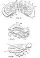
- FIG. 5 The invention is illustrated in Fig. 5.
- Figs. 1-4 which do not show most portions of the invention, are used to describe generally a cartridge assembly in which the invention can be used.
- a cartridge assembly according to Figs. 1-4 is subject of co-pending patent application EP 79 102 786.5.
- the cartridge assembly shown in exploded perspective in Fig. 1 includes a disk shaped film unit 10, a separator layer 12, a cover member 14, and a casing 16 with top and bottom parts 18 and 20, respectively.
- the top and bottom parts 18 and 20 of the casing form walls which enclose the film unit, the separator layer and the cover member.
- the film unit 10 shown enlarged and in partial section in Fig. 2, includes a rigid core 22, a photographic film disk 24, and a mounting ring 26.
- the film disk is illustrated as having a generally circular outer perimeter, but other non-circular (e.g. polygonal) shapes, such as hexagonal or octagonal may be used.
- the film disk 24 comprises a moderately flexible but self-supporting base sheet formed of, for example, cellulose acetate or poly(ethylene terephthalate) and carries photosensitive layers on a face thereof. It is constructed to record photographic images in a plurality of image areas which are spaced along an annular exposure region concentric with the film unit axis. The image areas can be defined by surrounding borders which have been photographically pre-exposed.
- the core 22 is preferably molded of a plastics material and includes an inner raised ring 28, surrounding a central opening, and an outer raised ring 30.
- a plurality of widely spaced teeth 34 and closely spaced upstanding teeth 35-38 are located radially inwardly from outer raised ring 30. These teeth cooperate with a ratchet pawl 40 (shown in Fig. 1 and detailed in Fig. 3) on the casing top part 18 in a manner disclosed hereinafter to inhibit rotation of the film unit 10 in other than one desired direction.
- a plurality of equally circumferentially spaced discontinuities in the form of recesses 42 are provided in the core 22 radially outwardly of the ring 30 for receiving a force tending to rotate the film unit 10.
- the perimeter of the film disk 24 contains a series of arcuately spaced positioning discontinuities, for example, notches 44 for use in termination of the indexing function and accurate positioning of each image area.
- An annular projection 46 (Fig. 2) of the core 22 rotatably rides in a groove 48 (Fig. 1) in the casing bottom part 20.
- the film disk 24 projects radially outwardly from the core 22 and lies in an annular recess 50 in the casing bottom part.
- an annular wall 56 extends around a central opening and a second annular wall 58 is spaced radially outwardly from wall 56.
- the top part includes the aforementioned ratchet pawl 40, two apertures 60 and 62, a tooth 63; an exposure window 64, a rib 66 surrounding exposure window 64, and a recess 70.
- the cover member 14 has a central opening 72 sized to receive annular wall 58 of casing top part 18 so that the cover member can rotate about the axis of the annular wall.
- the cover member is formed of suitably thin but relatively stiff opaque sheet plastics material and includes a generally fan-shaped leaf portion 74 sized to cover the exposure window 64. The passage of light rays through the exposure window 64 and onto photosensitive film disk 24 when the cartridge assembly is not protectively encased by a camera is precluded by means of the leaf portion 74 and the separator layer 12. Lips 76 and 78 extend over portions of rib 66 to form a light baffle.
- a locking mechanism for preventing inadvertent rotation of the cover member when the cartridge assembly is not in a camera includes a tab 80 (detailed in Fig. 4) on the cover member.
- the tab is aligned with the aperture 60 and engages the tooth 63 of the casing top part when the leaf portion 74 is aligned with the exposure window 64.
- the tab 80 is depressable by a camera pin 82 to disable the locking mechanism when the cartridge assembly is received in a camera.
- a discontinuity illustrated as a hole 84 in cover member 14 is aligned with the aperture 62 and is engageable by a camera indexing mechanism for rotating the cover member.
- a ratchet pawl 88 extends from the cover member 14 toward the core 22 and is aligned with the recesses 42 on the core.
- the pawl 88 is an engaging structure associated with the cover member 14 which cooperates with the recesses 42, to rotate the film unit 10 in response to reciprocative rotation of the cover member 14 on a path about the annular wall 58.
- the separator layer-12 is formed of an opaque sheet material and has a central aperture 90 sized to admit the outer ring 30 of the core 22 and to conform to the inside diameter of the annular wall 58 of the casing top part.
- a recess 92 in the separator layer 12 receives the core 22, and a window 94 is aligned with exposure window 64".
- An aperture 95 is aligned with recesses 42 on the core 22.
- cover member 14 Before the cartridge assembly is loaded into a camera, cover member 14 is held against rotation in one direction in casing 16 by engagement of lip 78 and rib 66, and in the other direction by tab 80 engaging tooth 63.
- Rotation of film disk 24, in casing 16 in one direction (counterclockwise in Fig. 1) is inhibited by pawl 40 on casing top part 18 lying between closely spaced teeth 35 and 36 as shown in Fig. 3.
- an antibackup pawl can be molded into separator layer 12 or casing bottom part 20 to engage the positioning discontinuities at a position on the periphery of disk 24 remote from the exposure window 64.
- a clockwise direction (Fig. 1) is prevented by an initial locking structure for the film disk 24.
- This structure is illustrated in Fig. 5, where the rotational direction of the film disk 24 is reversed from Fig. 1.
- An initial lock pawl 401 molded.into cover member 14 extends through a hole 402 in separator layer 12 to engage a positioning discontinuity 44 to prevent movement in the other direction.
- the tab 80 is depressed to unlock the cover member and the cover member is moved (counterclockwise as shown in Fig. 5)
- the pawl 401 moves out of hole 402 and is prevented from engaging discontinuity 44 by separator layer 12.
- Film disk 24 is now free to move in one direction.
- This structure has the important advantage of providing a positive lock on the film disk which cannot be overcome by manual turning of the core when the cartridge is outside the camera. It also is totally released prior to film unit advance which reduces the torque necessary to begin rotation of the film disk.
- This feature has broader application than use in cartridge assemblies in which film units are driven by the cover member. It also can be used with a cartridge assembly in which the film unit is driven directly by the camera.
- the cover member 14 Upon completion of exposure of the film disk 24 or at any intermediate position, the cover member 14 can be moved to its covering position.
- the cartridge assembly may now be removed from the camera, whereupon tab 80 abuts tooth 63 on casing top part 18 to inhibit inadvertent rotation of cover member 14 while the cartridge assembly is out of the camera.
Landscapes
- Physics & Mathematics (AREA)
- General Physics & Mathematics (AREA)
- Details Of Cameras Including Film Mechanisms (AREA)
- Camera Bodies And Camera Details Or Accessories (AREA)
- Structure And Mechanism Of Cameras (AREA)
- Blocking Light For Cameras (AREA)
Abstract
Description
- The present invention relates to photographic film cartridge assemblies of the type including a disk shaped film unit rotatably mounted in a casing.
- DT-OS 28 09 856 to Harvey discloses a photographic film cartridge assembly having a film disk mounted in a casing for rotation past an exposure window. A cover member protects the exposure window when the cartridge is outside of a camera and is movable between exposure window covering and uncovering positions.
- The Harvey cartridge assembly has a lock preventing rotation of the cover member when the cartridge assembly is outside a camera. The lock is releasable by a camera pin when the cartridge assembly is inserted in a camera, thereby permitting rotation of the cover member.
- The Harvey patent application recognizes the desirability of a lock on the film disk. Because the cover member and the film disk in the Harvey disclosure are both fixed to a rigid core, the one releasable lock also prevents movement of the film disk. Therefore, only one release structure need be incorporated into the camera to unlock both structures. However, fixing the cover member to the core prevents a film disk from being exposed in the area behind the cover member. To expose the area of a film disk behind the cover member, the cover member must be movable relative to the film disk as in other prior structures, see U.S. Patent 1,410,029, Niell.
- Although an overrideable detent inhibiting movement of the film disk could be used, the extra resistance would be objectionable especially if an electric motor drive camera is used. Since even in such electric drive cameras, movement of the cover member is likely to be accomplished manually, a detent on the cover member, while not ideal, would be less objectionable.
- It is the object of this invention to provide a releasable locking mechanism for a film disk in a cartridge assembly which cartridge assembly has a separately movable cover member and which locking mechanism does not require a camera release structure separate from whatever camera structure permits or causes movement of the cover member.
- This object is accomplished by a lock preventing movement of the film disk relative to the exposure window when the cover member is in its exposure window covering position, which lock is releasable in response to movement of the cover member toward its uncovering position.
- According to a preferred embodiment, the cartridge assembly includes a separator layer between the film disk and the cover member. The lock is a pawl fixed to the cover member and extending into a discontinuity in the film disk through a hole in the separator layer. Movement of the cover member toward its uncovering position moves the pawl to a position out of alignment with the hole, in which position the pawl is prevented by the separator layer from engaging a discontinuity, thereby permitting rotation. of the film unit.
- In the detailed description of the preferred embodiments of the invention presented below, reference is made to the accompanying drawings in which:
- Fig. 1 is an exploded perspective view of an unassembled photographic cartridge assembly in which the present invention can be used.
- Figs. 2-4 are enlarged views of details of the photographic cartridge assembly of Fig. 1;
- Fig. 5 is an exploded perspective view of a film unit, separator layer and cover member illustrating the film disk locking structure for the cartridge assembly shown in Fig. 1.
- The invention is illustrated in Fig. 5. However, Figs. 1-4, which do not show most portions of the invention, are used to describe generally a cartridge assembly in which the invention can be used. A cartridge assembly according to Figs. 1-4 is subject of co-pending patent application EP 79 102 786.5.
- The cartridge assembly, shown in exploded perspective in Fig. 1 includes a disk shaped
film unit 10, aseparator layer 12, acover member 14, and acasing 16 with top andbottom parts bottom parts - The
film unit 10, shown enlarged and in partial section in Fig. 2, includes arigid core 22, aphotographic film disk 24, and amounting ring 26. The film disk is illustrated as having a generally circular outer perimeter, but other non-circular (e.g. polygonal) shapes, such as hexagonal or octagonal may be used. - The
film disk 24, comprises a moderately flexible but self-supporting base sheet formed of, for example, cellulose acetate or poly(ethylene terephthalate) and carries photosensitive layers on a face thereof. It is constructed to record photographic images in a plurality of image areas which are spaced along an annular exposure region concentric with the film unit axis. The image areas can be defined by surrounding borders which have been photographically pre-exposed. - The
core 22 is preferably molded of a plastics material and includes an inner raisedring 28, surrounding a central opening, and an outer raisedring 30. - According to Fig. 3, a plurality of widely spaced
teeth 34 and closely spaced upstanding teeth 35-38 are located radially inwardly from outer raisedring 30. These teeth cooperate with a ratchet pawl 40 (shown in Fig. 1 and detailed in Fig. 3) on the casingtop part 18 in a manner disclosed hereinafter to inhibit rotation of thefilm unit 10 in other than one desired direction. - A plurality of equally circumferentially spaced discontinuities in the form of
recesses 42 are provided in thecore 22 radially outwardly of thering 30 for receiving a force tending to rotate thefilm unit 10. The perimeter of thefilm disk 24 contains a series of arcuately spaced positioning discontinuities, for example,notches 44 for use in termination of the indexing function and accurate positioning of each image area. - An annular projection 46 (Fig. 2) of the
core 22 rotatably rides in a groove 48 (Fig. 1) in thecasing bottom part 20. Thefilm disk 24 projects radially outwardly from thecore 22 and lies in anannular recess 50 in the casing bottom part. - Referring now to the casing
top part 18, anannular wall 56 extends around a central opening and a secondannular wall 58 is spaced radially outwardly fromwall 56. The top part includes theaforementioned ratchet pawl 40, twoapertures tooth 63; anexposure window 64, arib 66 surroundingexposure window 64, and arecess 70. - The
cover member 14 has a central opening 72 sized to receiveannular wall 58 of casingtop part 18 so that the cover member can rotate about the axis of the annular wall. The cover member is formed of suitably thin but relatively stiff opaque sheet plastics material and includes a generally fan-shaped leaf portion 74 sized to cover theexposure window 64. The passage of light rays through theexposure window 64 and ontophotosensitive film disk 24 when the cartridge assembly is not protectively encased by a camera is precluded by means of the leaf portion 74 and theseparator layer 12.Lips rib 66 to form a light baffle. - A locking mechanism for preventing inadvertent rotation of the cover member when the cartridge assembly is not in a camera includes a tab 80 (detailed in Fig. 4) on the cover member. The tab is aligned with the
aperture 60 and engages thetooth 63 of the casing top part when the leaf portion 74 is aligned with theexposure window 64. Thetab 80 is depressable by acamera pin 82 to disable the locking mechanism when the cartridge assembly is received in a camera. - Another discontinuity, illustrated as a
hole 84 incover member 14, is aligned with theaperture 62 and is engageable by a camera indexing mechanism for rotating the cover member. Aratchet pawl 88 extends from thecover member 14 toward thecore 22 and is aligned with therecesses 42 on the core. Thepawl 88 is an engaging structure associated with thecover member 14 which cooperates with therecesses 42, to rotate thefilm unit 10 in response to reciprocative rotation of thecover member 14 on a path about theannular wall 58. - The separator layer-12 is formed of an opaque sheet material and has a
central aperture 90 sized to admit theouter ring 30 of thecore 22 and to conform to the inside diameter of theannular wall 58 of the casing top part. Arecess 92 in theseparator layer 12 receives thecore 22, and awindow 94 is aligned withexposure window 64". Anaperture 95 is aligned withrecesses 42 on thecore 22. - Before the cartridge assembly is loaded into a camera,
cover member 14 is held against rotation in one direction incasing 16 by engagement oflip 78 andrib 66, and in the other direction bytab 80engaging tooth 63. Rotation offilm disk 24, incasing 16 in one direction (counterclockwise in Fig. 1) is inhibited bypawl 40 on casingtop part 18 lying between closely spacedteeth separator layer 12 orcasing bottom part 20 to engage the positioning discontinuities at a position on the periphery ofdisk 24 remote from theexposure window 64. - Movement in a clockwise direction (Fig. 1) is prevented by an initial locking structure for the
film disk 24. This structure is illustrated in Fig. 5, where the rotational direction of thefilm disk 24 is reversed from Fig. 1. Prior to insertion into a camera for the first exposure, movement in one direction is prevented by engagement between post 98 (Fig. 1) and post 32 (Fig. 3) and/or by one of the antibackup structures mentioned above. Aninitial lock pawl 401 molded.intocover member 14 extends through ahole 402 inseparator layer 12 to engage apositioning discontinuity 44 to prevent movement in the other direction. When thetab 80 is depressed to unlock the cover member and the cover member is moved (counterclockwise as shown in Fig. 5), thepawl 401 moves out ofhole 402 and is prevented from engagingdiscontinuity 44 byseparator layer 12.Film disk 24 is now free to move in one direction. - This structure has the important advantage of providing a positive lock on the film disk which cannot be overcome by manual turning of the core when the cartridge is outside the camera. It also is totally released prior to film unit advance which reduces the torque necessary to begin rotation of the film disk. This feature has broader application than use in cartridge assemblies in which film units are driven by the cover member. It also can be used with a cartridge assembly in which the film unit is driven directly by the camera.
- Upon completion of exposure of the
film disk 24 or at any intermediate position, thecover member 14 can be moved to its covering position. The cartridge assembly may now be removed from the camera, whereupontab 80 abutstooth 63 on casingtop part 18 to inhibit inadvertent rotation ofcover member 14 while the cartridge assembly is out of the camera. - With any of the embodiments, complexity in the cartridge assembly does not generally add substantial cost, because the core, cover member and casing are all made of plastic in which pawls and discontinuities can be readily molded or otherwise formed.
- The invention has been described in detail with particular reference to preferred embodiments thereof, but it will be understood that variations and modifications can be effected within the scope of the invention as defined in the appended claims.
Claims (6)
Priority Applications (1)
| Application Number | Priority Date | Filing Date | Title |
|---|---|---|---|
| AT80200635T ATE1726T1 (en) | 1979-08-03 | 1980-08-03 | CASSETTE FOR PHOTOGRAPHIC FILM. |
Applications Claiming Priority (1)
| Application Number | Priority Date | Filing Date | Title |
|---|---|---|---|
| US05/931,053 US4194822A (en) | 1978-08-04 | 1978-08-04 | Photographic film cartridge assembly and camera |
Related Parent Applications (2)
| Application Number | Title | Priority Date | Filing Date |
|---|---|---|---|
| EP79102786.5 Division | 1979-08-03 | ||
| EP79102786A Division EP0011678A3 (en) | 1978-08-04 | 1979-08-03 | Photographic film cartridge assembly and still camera |
Publications (3)
| Publication Number | Publication Date |
|---|---|
| EP0019986A2 true EP0019986A2 (en) | 1980-12-10 |
| EP0019986A3 EP0019986A3 (en) | 1981-02-11 |
| EP0019986B1 EP0019986B1 (en) | 1982-10-27 |
Family
ID=25460153
Family Applications (2)
| Application Number | Title | Priority Date | Filing Date |
|---|---|---|---|
| EP79102786A Withdrawn EP0011678A3 (en) | 1978-08-04 | 1979-08-03 | Photographic film cartridge assembly and still camera |
| EP80200635A Expired EP0019986B1 (en) | 1978-08-04 | 1979-08-03 | Photographic film cartridge assembly |
Family Applications Before (1)
| Application Number | Title | Priority Date | Filing Date |
|---|---|---|---|
| EP79102786A Withdrawn EP0011678A3 (en) | 1978-08-04 | 1979-08-03 | Photographic film cartridge assembly and still camera |
Country Status (8)
| Country | Link |
|---|---|
| US (1) | US4194822A (en) |
| EP (2) | EP0011678A3 (en) |
| JP (1) | JPS5815782B2 (en) |
| AU (1) | AU530197B2 (en) |
| GB (1) | GB2027225B (en) |
| HK (1) | HK4583A (en) |
| MY (1) | MY8400016A (en) |
| SG (1) | SG55882G (en) |
Cited By (1)
| Publication number | Priority date | Publication date | Assignee | Title |
|---|---|---|---|---|
| DE3721739A1 (en) * | 1987-07-01 | 1989-01-12 | Igor Groza | Digital recording cassette |
Families Citing this family (27)
| Publication number | Priority date | Publication date | Assignee | Title |
|---|---|---|---|---|
| DE2963936D1 (en) * | 1979-08-03 | 1982-12-02 | Eastman Kodak Co | Photographic film cartridge assembly |
| DE2934985C2 (en) * | 1979-08-30 | 1982-05-06 | Agfa-Gevaert Ag, 5090 Leverkusen | Apparatus for projecting a license plate image onto film. |
| US4252430A (en) * | 1979-10-12 | 1981-02-24 | Eastman Kodak Company | Film processing apparatus |
| EP0031931B1 (en) * | 1979-12-26 | 1984-03-21 | EASTMAN KODAK COMPANY (a New Jersey corporation) | Film cartridge assembly with light sealing and pressure applying means |
| US4265525A (en) * | 1979-12-26 | 1981-05-05 | Polaroid Corporation | Disc camera |
| JPS5624346A (en) * | 1980-03-04 | 1981-03-07 | Eastman Kodak Co | Photographic cartridge assembly |
| US4403855A (en) * | 1982-02-18 | 1983-09-13 | Pako Corporation | Disc film frame position indicator |
| US4392743A (en) * | 1982-02-18 | 1983-07-12 | Pako Corporation | Disc film advance assembly |
| US4396282A (en) * | 1982-02-18 | 1983-08-02 | Pako Corporation | Disc film holder for photographic printer |
| US4395793A (en) * | 1982-02-18 | 1983-08-02 | Pako Corporation | Photographic film cleaner |
| US4396283A (en) * | 1982-02-18 | 1983-08-02 | Pako Corporation | Neghold assembly for photographic printer |
| USD279788S (en) | 1982-09-08 | 1985-07-23 | Minolta Camera Kabushiki Kaisha | Photographic camera |
| US4429980A (en) | 1982-10-05 | 1984-02-07 | Pako Corporation | Magnetic drive mechanism for film disc processor |
| US4432629A (en) * | 1982-10-05 | 1984-02-21 | Pako Corporation | Dryer apparatus for film disc processor |
| US4431294A (en) * | 1982-10-05 | 1984-02-14 | Pako Corporation | Rotation failure sensor for film disc processor |
| US4456355A (en) * | 1982-10-05 | 1984-06-26 | Pako Corporation | Control apparatus for film disc processor |
| US4449806A (en) * | 1983-06-01 | 1984-05-22 | W. Haking Enterprises Limited | Film advance mechanism for disc camera |
| US4584615A (en) * | 1984-02-22 | 1986-04-22 | Minnesota Mining And Manufacturing Company | Black and white disc construction to record color images |
| JPS6116971A (en) * | 1984-07-04 | 1986-01-24 | Kenji Matsumori | Anticorrosive coating for lining inner surfaces of pipings |
| DE3712473A1 (en) * | 1986-04-14 | 1987-10-15 | Canon Kk | IMAGE RECORDING AND / OR IMAGE PLAYER |
| US4685788A (en) * | 1986-06-30 | 1987-08-11 | Eastman Kodak Company | Film registration apparatus |
| US5483310A (en) * | 1988-08-05 | 1996-01-09 | Minolta Camera Kabushiki Kaisha | Film cartridge and a camera employing the film cartridge |
| US5220371A (en) * | 1988-08-05 | 1993-06-15 | Minolta Camera Kabushiki Kaisha | Film cartridge and a camera employing the film cartridge |
| US5231438A (en) * | 1991-11-25 | 1993-07-27 | Eastman Kodak Company | Camera with interlock for cover piece and cartridge light shield |
| US5319630A (en) * | 1991-12-24 | 1994-06-07 | Optex Corporation | Light-tight optical disk cartridge |
| JP4644035B2 (en) * | 2005-05-25 | 2011-03-02 | ミライアル株式会社 | Single wafer storage container |
| GB2535656A (en) | 2013-09-27 | 2016-08-24 | Gree Inc | Computer control method, control program and computer |
Family Cites Families (10)
| Publication number | Priority date | Publication date | Assignee | Title |
|---|---|---|---|---|
| US1410029A (en) * | 1918-06-26 | 1922-03-21 | Niell Magnus | Camera |
| US1563551A (en) * | 1920-05-03 | 1925-12-01 | Pictures Dev Co | Disk-record apparatus |
| GB225115A (en) * | 1924-04-07 | 1924-11-27 | Mills Novelty Co | Improvements in or relating to cinematograph apparatus |
| US2188974A (en) * | 1939-03-20 | 1940-02-06 | Jr James J Dilks | Camera |
| CH222819A (en) * | 1940-03-16 | 1942-08-15 | Kurt Steiner | Pocket camera. |
| US2531651A (en) * | 1947-05-07 | 1950-11-28 | American Safety Razor Corp | Film cassette for cameras |
| US2625087A (en) * | 1949-05-12 | 1953-01-13 | Steineck Rudolf | Construction for cameras |
| CH359024A (en) * | 1959-12-02 | 1961-12-15 | Manuf D Horlogerie Frey & Co S | Miniature camera with disk-shaped image holder |
| CH359023A (en) * | 1960-01-29 | 1961-12-15 | Manuf D Horlogerie Frey & Co S | Circular cassette camera |
| BR7801359A (en) * | 1977-03-07 | 1978-09-26 | Eastman Kodak Co | PHOTOGRAPHIC FILM UNIT, FINE LAMINARY PHOTO FILM CARTRIDGE SET, AND CAMERA TO RECEIVE A FILM UNIT |
-
1978
- 1978-08-04 US US05/931,053 patent/US4194822A/en not_active Expired - Lifetime
-
1979
- 1979-04-05 GB GB7911900A patent/GB2027225B/en not_active Expired
- 1979-08-03 EP EP79102786A patent/EP0011678A3/en not_active Withdrawn
- 1979-08-03 EP EP80200635A patent/EP0019986B1/en not_active Expired
- 1979-08-03 AU AU49555/79A patent/AU530197B2/en not_active Expired
- 1979-08-04 JP JP54099803A patent/JPS5815782B2/en not_active Expired
-
1982
- 1982-10-29 SG SG558/82A patent/SG55882G/en unknown
-
1983
- 1983-01-27 HK HK45/83A patent/HK4583A/en not_active IP Right Cessation
-
1984
- 1984-12-30 MY MY16/84A patent/MY8400016A/en unknown
Cited By (1)
| Publication number | Priority date | Publication date | Assignee | Title |
|---|---|---|---|---|
| DE3721739A1 (en) * | 1987-07-01 | 1989-01-12 | Igor Groza | Digital recording cassette |
Also Published As
| Publication number | Publication date |
|---|---|
| EP0011678A2 (en) | 1980-06-11 |
| JPS5815782B2 (en) | 1983-03-28 |
| SG55882G (en) | 1983-09-02 |
| EP0019986A3 (en) | 1981-02-11 |
| GB2027225A (en) | 1980-02-13 |
| AU4955579A (en) | 1980-02-07 |
| EP0011678A3 (en) | 1980-06-25 |
| AU530197B2 (en) | 1983-07-07 |
| EP0019986B1 (en) | 1982-10-27 |
| JPS5525096A (en) | 1980-02-22 |
| MY8400016A (en) | 1984-12-31 |
| GB2027225B (en) | 1982-08-04 |
| US4194822A (en) | 1980-03-25 |
| HK4583A (en) | 1983-01-27 |
Similar Documents
| Publication | Publication Date | Title |
|---|---|---|
| EP0019986B1 (en) | Photographic film cartridge assembly | |
| US5357303A (en) | Film cassette with lockable light shield | |
| EP0540938B1 (en) | Film cassette with an integrated light blocking and spool locking device | |
| CN1030482C (en) | Camera apparatus for preventing load of exposed film | |
| EP0664476B1 (en) | Film cassette with lockable light shield | |
| US5600395A (en) | One-time-use camera has driver for closing film cassette which cannot re-open closed cassette | |
| JPH07199329A (en) | Film cassette having film spool with bar code and double-exposure preventing function of film | |
| US4966334A (en) | Cable reel | |
| US5248108A (en) | Film cassette with unitary film stripper and light blocking device | |
| CA1098749A (en) | Disk-shaped film unit and hub cartridge assembly | |
| US4255034A (en) | Film retention in cartridge assembly | |
| JPS5814667B2 (en) | Film cartridge assembly | |
| US5608480A (en) | One-time-use camera with stop-protrusion for engaging open light lock of cassette to prevent cassette from dislodging lid closing chamber | |
| US5715494A (en) | Film cartridge with film-exposed visual indicator | |
| US4268145A (en) | Film cartridge assembly | |
| US5295634A (en) | Film cassette with spool core having fastening hook | |
| US4325619A (en) | Camera | |
| US4196985A (en) | Frame-counting device for use with film cassette | |
| CA1145182A (en) | Film retention in cartridge assembly | |
| EP0625725A1 (en) | Film cassette with film exposure-status indicator device | |
| US5988895A (en) | Film cartridge with visual exposure status indicator | |
| US5270760A (en) | Film cassette with internal film drive | |
| KR820001487B1 (en) | Photographic cameras | |
| JPH09204015A (en) | Photographic roll film cartridge | |
| HK1011420A (en) | Film cassette with lockable light shield |
Legal Events
| Date | Code | Title | Description |
|---|---|---|---|
| PUAI | Public reference made under article 153(3) epc to a published international application that has entered the european phase |
Free format text: ORIGINAL CODE: 0009012 |
|
| AK | Designated contracting states |
Designated state(s): AT BE CH DE FR IT NL SE |
|
| PUAL | Search report despatched |
Free format text: ORIGINAL CODE: 0009013 |
|
| AK | Designated contracting states |
Designated state(s): AT BE CH DE FR IT NL SE |
|
| 17P | Request for examination filed |
Effective date: 19800708 |
|
| DET | De: translation of patent claims | ||
| ITF | It: translation for a ep patent filed | ||
| GRAA | (expected) grant |
Free format text: ORIGINAL CODE: 0009210 |
|
| AC | Divisional application: reference to earlier application |
Ref document number: 11678 Country of ref document: EP |
|
| AK | Designated contracting states |
Designated state(s): AT BE CH DE FR IT NL SE |
|
| REF | Corresponds to: |
Ref document number: 1726 Country of ref document: AT Date of ref document: 19821115 Kind code of ref document: T |
|
| REF | Corresponds to: |
Ref document number: 2963936 Country of ref document: DE Date of ref document: 19821202 |
|
| ET | Fr: translation filed | ||
| ITTA | It: last paid annual fee | ||
| EAL | Se: european patent in force in sweden |
Ref document number: 80200635.3 |
|
| PGFP | Annual fee paid to national office [announced via postgrant information from national office to epo] |
Ref country code: CH Payment date: 19950814 Year of fee payment: 17 |
|
| PGFP | Annual fee paid to national office [announced via postgrant information from national office to epo] |
Ref country code: BE Payment date: 19950829 Year of fee payment: 17 |
|
| PGFP | Annual fee paid to national office [announced via postgrant information from national office to epo] |
Ref country code: SE Payment date: 19960718 Year of fee payment: 18 |
|
| PG25 | Lapsed in a contracting state [announced via postgrant information from national office to epo] |
Ref country code: CH Effective date: 19960831 Ref country code: BE Effective date: 19960831 |
|
| BERE | Be: lapsed |
Owner name: EASTMAN KODAK CY Effective date: 19960831 |
|
| REG | Reference to a national code |
Ref country code: CH Ref legal event code: PL |
|
| PG25 | Lapsed in a contracting state [announced via postgrant information from national office to epo] |
Ref country code: SE Free format text: LAPSE BECAUSE OF NON-PAYMENT OF DUE FEES Effective date: 19970804 |
|
| EUG | Se: european patent has lapsed |
Ref document number: 80200635.3 |
|
| PGFP | Annual fee paid to national office [announced via postgrant information from national office to epo] |
Ref country code: NL Payment date: 19980623 Year of fee payment: 20 |
|
| PGFP | Annual fee paid to national office [announced via postgrant information from national office to epo] |
Ref country code: AT Payment date: 19980707 Year of fee payment: 20 |
|
| PGFP | Annual fee paid to national office [announced via postgrant information from national office to epo] |
Ref country code: DE Payment date: 19980728 Year of fee payment: 20 |
|
| PGFP | Annual fee paid to national office [announced via postgrant information from national office to epo] |
Ref country code: FR Payment date: 19980806 Year of fee payment: 20 |
|
| PG25 | Lapsed in a contracting state [announced via postgrant information from national office to epo] |
Ref country code: NL Free format text: LAPSE BECAUSE OF EXPIRATION OF PROTECTION Effective date: 19990803 Ref country code: AT Free format text: LAPSE BECAUSE OF EXPIRATION OF PROTECTION Effective date: 19990803 |
|
| PLBE | No opposition filed within time limit |
Free format text: ORIGINAL CODE: 0009261 |
|
| STAA | Information on the status of an ep patent application or granted ep patent |
Free format text: STATUS: NO OPPOSITION FILED WITHIN TIME LIMIT |