EP0019850B1 - Halogen incandescent lamp - Google Patents
Halogen incandescent lamp Download PDFInfo
- Publication number
- EP0019850B1 EP0019850B1 EP80102835A EP80102835A EP0019850B1 EP 0019850 B1 EP0019850 B1 EP 0019850B1 EP 80102835 A EP80102835 A EP 80102835A EP 80102835 A EP80102835 A EP 80102835A EP 0019850 B1 EP0019850 B1 EP 0019850B1
- Authority
- EP
- European Patent Office
- Prior art keywords
- bulb
- wires
- incandescent lamp
- halogen
- lead
- Prior art date
- Legal status (The legal status is an assumption and is not a legal conclusion. Google has not performed a legal analysis and makes no representation as to the accuracy of the status listed.)
- Expired
Links
- 229910052736 halogen Inorganic materials 0.000 title claims description 63
- 150000002367 halogens Chemical class 0.000 title claims description 63
- ZOKXTWBITQBERF-UHFFFAOYSA-N Molybdenum Chemical compound [Mo] ZOKXTWBITQBERF-UHFFFAOYSA-N 0.000 claims description 31
- 239000011733 molybdenum Substances 0.000 claims description 31
- 229910052750 molybdenum Inorganic materials 0.000 claims description 31
- 239000007789 gas Substances 0.000 claims description 28
- 239000005354 aluminosilicate glass Substances 0.000 claims description 16
- 229910052721 tungsten Inorganic materials 0.000 claims description 15
- 239000010937 tungsten Substances 0.000 claims description 15
- WFKWXMTUELFFGS-UHFFFAOYSA-N tungsten Chemical compound [W] WFKWXMTUELFFGS-UHFFFAOYSA-N 0.000 claims description 14
- WKBOTKDWSSQWDR-UHFFFAOYSA-N Bromine atom Chemical compound [Br] WKBOTKDWSSQWDR-UHFFFAOYSA-N 0.000 claims description 11
- GDTBXPJZTBHREO-UHFFFAOYSA-N bromine Substances BrBr GDTBXPJZTBHREO-UHFFFAOYSA-N 0.000 claims description 11
- 229910052794 bromium Inorganic materials 0.000 claims description 11
- UFHFLCQGNIYNRP-UHFFFAOYSA-N Hydrogen Chemical compound [H][H] UFHFLCQGNIYNRP-UHFFFAOYSA-N 0.000 claims description 7
- CPELXLSAUQHCOX-UHFFFAOYSA-N Hydrogen bromide Chemical compound Br CPELXLSAUQHCOX-UHFFFAOYSA-N 0.000 claims description 6
- PXHVJJICTQNCMI-UHFFFAOYSA-N Nickel Chemical compound [Ni] PXHVJJICTQNCMI-UHFFFAOYSA-N 0.000 claims description 5
- 125000005843 halogen group Chemical group 0.000 claims description 5
- -1 hydrocarbon bromide Chemical class 0.000 claims description 5
- 239000011261 inert gas Substances 0.000 claims description 5
- 239000000203 mixture Substances 0.000 claims description 5
- 239000004215 Carbon black (E152) Substances 0.000 claims description 3
- 229930195733 hydrocarbon Natural products 0.000 claims description 3
- 229910000042 hydrogen bromide Inorganic materials 0.000 claims description 3
- 125000004429 atom Chemical group 0.000 claims description 2
- 239000004615 ingredient Substances 0.000 claims description 2
- 229910052759 nickel Inorganic materials 0.000 claims description 2
- 125000004435 hydrogen atom Chemical group [H]* 0.000 claims 1
- VYPSYNLAJGMNEJ-UHFFFAOYSA-N Silicium dioxide Chemical compound O=[Si]=O VYPSYNLAJGMNEJ-UHFFFAOYSA-N 0.000 description 19
- 239000011888 foil Substances 0.000 description 18
- 239000000463 material Substances 0.000 description 17
- 238000007789 sealing Methods 0.000 description 8
- 238000004519 manufacturing process Methods 0.000 description 7
- 238000000034 method Methods 0.000 description 7
- 239000001257 hydrogen Substances 0.000 description 6
- 229910052739 hydrogen Inorganic materials 0.000 description 6
- XKRFYHLGVUSROY-UHFFFAOYSA-N Argon Chemical compound [Ar] XKRFYHLGVUSROY-UHFFFAOYSA-N 0.000 description 4
- 238000005530 etching Methods 0.000 description 4
- 230000008020 evaporation Effects 0.000 description 4
- 238000001704 evaporation Methods 0.000 description 4
- 239000011521 glass Substances 0.000 description 4
- 230000000704 physical effect Effects 0.000 description 4
- 230000007547 defect Effects 0.000 description 3
- 230000003647 oxidation Effects 0.000 description 3
- 238000007254 oxidation reaction Methods 0.000 description 3
- 229910052786 argon Inorganic materials 0.000 description 2
- 238000005219 brazing Methods 0.000 description 2
- 230000015556 catabolic process Effects 0.000 description 2
- 238000010276 construction Methods 0.000 description 2
- 238000005286 illumination Methods 0.000 description 2
- 238000004904 shortening Methods 0.000 description 2
- 230000001629 suppression Effects 0.000 description 2
- 238000003466 welding Methods 0.000 description 2
- ZCYVEMRRCGMTRW-UHFFFAOYSA-N 7553-56-2 Chemical compound [I] ZCYVEMRRCGMTRW-UHFFFAOYSA-N 0.000 description 1
- CPELXLSAUQHCOX-UHFFFAOYSA-M Bromide Chemical compound [Br-] CPELXLSAUQHCOX-UHFFFAOYSA-M 0.000 description 1
- ZAMOUSCENKQFHK-UHFFFAOYSA-N Chlorine atom Chemical compound [Cl] ZAMOUSCENKQFHK-UHFFFAOYSA-N 0.000 description 1
- PNEYBMLMFCGWSK-UHFFFAOYSA-N aluminium oxide Inorganic materials [O-2].[O-2].[O-2].[Al+3].[Al+3] PNEYBMLMFCGWSK-UHFFFAOYSA-N 0.000 description 1
- QVGXLLKOCUKJST-UHFFFAOYSA-N atomic oxygen Chemical compound [O] QVGXLLKOCUKJST-UHFFFAOYSA-N 0.000 description 1
- 230000005540 biological transmission Effects 0.000 description 1
- 230000015572 biosynthetic process Effects 0.000 description 1
- 229910052801 chlorine Inorganic materials 0.000 description 1
- 239000000460 chlorine Substances 0.000 description 1
- 229910052593 corundum Inorganic materials 0.000 description 1
- 230000002542 deteriorative effect Effects 0.000 description 1
- 230000002349 favourable effect Effects 0.000 description 1
- 230000004907 flux Effects 0.000 description 1
- 238000007496 glass forming Methods 0.000 description 1
- 238000010438 heat treatment Methods 0.000 description 1
- 239000012535 impurity Substances 0.000 description 1
- 229910052740 iodine Inorganic materials 0.000 description 1
- 239000011630 iodine Substances 0.000 description 1
- 230000008018 melting Effects 0.000 description 1
- 238000002844 melting Methods 0.000 description 1
- 229910052751 metal Inorganic materials 0.000 description 1
- 239000002184 metal Substances 0.000 description 1
- 238000013021 overheating Methods 0.000 description 1
- 239000001301 oxygen Substances 0.000 description 1
- 229910052760 oxygen Inorganic materials 0.000 description 1
- 230000002093 peripheral effect Effects 0.000 description 1
- 230000003449 preventive effect Effects 0.000 description 1
- 230000035939 shock Effects 0.000 description 1
- 239000000126 substance Substances 0.000 description 1
- 229910001845 yogo sapphire Inorganic materials 0.000 description 1
Images
Classifications
-
- H—ELECTRICITY
- H01—ELECTRIC ELEMENTS
- H01K—ELECTRIC INCANDESCENT LAMPS
- H01K1/00—Details
- H01K1/28—Envelopes; Vessels
-
- C—CHEMISTRY; METALLURGY
- C03—GLASS; MINERAL OR SLAG WOOL
- C03C—CHEMICAL COMPOSITION OF GLASSES, GLAZES OR VITREOUS ENAMELS; SURFACE TREATMENT OF GLASS; SURFACE TREATMENT OF FIBRES OR FILAMENTS MADE FROM GLASS, MINERALS OR SLAGS; JOINING GLASS TO GLASS OR OTHER MATERIALS
- C03C3/00—Glass compositions
- C03C3/04—Glass compositions containing silica
- C03C3/076—Glass compositions containing silica with 40% to 90% silica, by weight
- C03C3/089—Glass compositions containing silica with 40% to 90% silica, by weight containing boron
- C03C3/091—Glass compositions containing silica with 40% to 90% silica, by weight containing boron containing aluminium
Definitions
- This invention relates to halogen incandescent lamps, more specifically to halogen incandescent lamps using aluminosilicate glass for bulb material.
- tungsten-filament incandescent lamps with halogen sealed therein are improved in compactness, efficiency and life performance, performing halogen cycles which will prevent bulb blackening till the end of the life. Accordingly, they are utilized in various fields of illumination.
- the temperature of a glowing bulb needs to be kept at a high temperature of approximately 250°C or higher lest tungsten halide should stick to the inside wall of the bulb during halogen cycles.
- quartz glass or high silica glass which can resist high heat load.
- quartz glass has favorable properties for the material for incandescent lamps, such as high heat-resisting property and tendency to discharge hardly any impurity gas at high temperature, it has a very small thermal expansion coefficient-5.6x10 -70 C -1 at 0 to 300°C.
- a filament is connected with a lead-in wire for the transmission of electric current from a power source.
- the thermal expansion coefficients of materials of the lead-in wire and bulb need be approximate to each other.
- the value of such coefficient is 37 x 10- 7 to 53x 10-70C-1 at 100 to 300°C, which is considerably greater than that of quartz glass.
- molybdenum foil of 20 to 30-,um thickness is used for the seal portion, and inner and outer lead-in wires are connected to both ends of the molybdenum foil, respectively.
- the use of hard or semi-hard glass for the bulb material which, unlike quartz glass and high silica glass, has a thermal expansion coefficient approximate to that of molybdenum.
- the aforesaid defect may be eliminated because molybdenum wires may be used in place of the molybdenum foil for the seal material.
- the bulb temperature will locally exceed 500°C. Since the strain point of hard or semi-hard glass, however, is lower than 500°C, the bulb may be damaged or broken.
- the molybdenum foil will have to be used for the seal metal if the bulb material is selected in consideration of heat-resisting property, while such heat-resisting property will become a problem if the bulb material is selected on the basis of the availability of molybdenum wires.
- An object of this invention is to provide a halogen incandescent lamp as a solution to all the aforementioned problems or drawbacks of the prior art halogen incandescent lamps.
- the present invention is intended to provide halogen incandescent lamp capable of preventing leakage at sealed portion caused by difference in thermal expansion coefficient between lead-in wire and bulb.
- a halogen incandescent lamp (1) performing halogen cycles in operation comprising
- This invention is based on a view that all the drawbacks of the prior art halogen incandescent lamps may be eliminated by using molybdenum wires as lead-in wires to be sealed in a bulb of a halogen incandescent lamp, and aluminosilicate glass as glass material with a thermal expansion coefficient approximate to that of the molybdenum wires and a relatively high strain point.
- the aluminosilicate glass forming the bulb of the halogen incandescent lamp of this invention has the following physical properties.
- Softening point 900 to 1,050°C.
- the aluminosilicate glass has the composition as follows:
- the bulb formed of the aluminosilicate glass with the above physical properties and/or composition has a thermal expansion coefficient approximate to that of molybdenum (37x 10- 7 to 53x10- 70 C -1 ), it is unnecessary to foliate the seal portions of the lead-in wires in the bulb. Further, since the strain point of the bulb material is 660°C or higher, the bulb will hardly suffer any undesirable cracks even if it is heated to a temperature required for the performance of halogen cycle, i.e. 250°C or higher.
- the aforementioned aluminosilicate glass ensures very high processibility for bulbs, and improves the sealing efficiency of the lead-in wires.
- the softening point of the aluminosilicate glass is about 700°C lower than that of quartz glass.
- the use of the aluminosilicate glass with the aforesaid physical properties as the bulb material has first enabled the manufacture of halogen incandescent lamps without using molybdenum foil and quartz glass that are poor in operating efficiency.
- a bulb of approximately 8-mm diameter and 25-mm length was formed by using such aluminosilicate glass, a tungsten filament of e.g. 12V, 40W (3.3A) was sealed in the bulb through the aid of molybdenum lead-in wires of 0.3-mm diameter so that the temperature of the inside wall of the bulb, when lighted, would reach 250°C or higher, and thus a halogen incandescent lamp was manufactured. When this lamp was lighted, the lead-in wires suffered no damage.
- the diameter of the lead-in wires at the seal portions must be 0.2 to 0.6 mm.
- the diameter should be in a range of 0.4 to 0.6 mm to ensure high sealing strength.
- Bromine is preferably used as the halogen to be contained in the bulb.
- 0.1x10 -7 to 0.5x10 -6 gram molecule of bromine is used for each cm 3 of bulb capacity. If the amount of bromine is less than 0.1 x 1 0-7 gram molecule cm 3 , halogen cycle will be retarded to quicken blackening that is caused by evaporated tungsten which comes out on the inside wall of the bulb without returning to the filament, thereby shortening the life of the lamp and substantially deteriorating luminous flux.
- bromine is more than 0.5x10 -6 gram molecule cm 3 on the other hand, extra portion of bromine will be condensed on the tungsten filament when the lamp is off or deposited on the surfaces of the lead wires which have not yet been heated to the full when the lamp is on.
- the condensed bromine will etch the filament and lead wires to reduce their strength and shorten the life of the lamp.
- halogen elements they are not suitable for this purpose; iodine tends to be condensed to color the bulb while the lamp is off, and chlorine will etch the filament and lead-in wires to a great degree.
- bromine it is necessary only that the above-mentioned amount of bromine should exist in the bulb, and a bromide such as hydrogen bromide or hydrocarbon bromide may be enclosed in the bulb to fulfill such requirement.
- a bromide such as hydrogen bromide or hydrocarbon bromide may be enclosed in the bulb to fulfill such requirement.
- hydrogen is contained in the gas enclosed in the bulb in order to prevent halogen from etching the filament and lead-in wires.
- Hydrogen may be used in the form of a single substance or hydrogen bromide or hydrocarbon bromide.
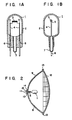
- FIGs. 1A and 1B are front and side views showing partial sections of a halogen incandescent lamp used for a sealed beam headlamp for an automobile, respectively.
- a halogen incandescent lamp 1 includes a bulb 2 and a tungsten filament 3 incorporated in the bulb 2.
- the bulb 2 which is made of aluminosilicate glass containing 57 wt.% of Si0 2 , 20 wt.% of Al 2 O 3 , 8 wt.% of MgO, 6 wt.% of CaO, 4 wt.% of B z 0 3 , and very small amounts of accompanying oxides and residuals, is a bottomed cylinder with an inside diameter of approximately 8 mm and a length of approximately 25 mm.
- the tungsten filament 3 has ratings of 12V and 60W so that the working temperature may be approximately 2,800°K.
- the tungsten filament 3 is supported by respective one ends 5 of a pair of inner lead-in wires 4 of molybdenum with a diameter of approximately 0.3 mm.
- the other ends of the inner lead-in wires are welded to outer lead-in wires 6 formed of nickel wires of about 1.0-mm diameter.
- a portion of the bulb 2 near fixed portions between these inner and outer lead-in wires 4 and 6 is pinch-sealed.
- a gas mixture of 0.3x10 -7 gram atom cm 3 of bromine and inert gas such as argon is enclosed in the bulb to attain the pressure inside the bulb of approximately 4 atm.
- the gas pressure inside the bulb is preferably 4x 10 5 to 10x 10 5 Pa as the total pressure or the sum of the pressure of halogen gas and the pressure of inert gas, e.g. argon. If the gas pressure is lower than 4x10 5 Pa, evaporation of the tungsten filament is accelerated when the lamp is lighted, thereby shortening the lamp life. If the gas pressure is higher than 4 x 10 5 Pa, the evaporation of the tungsten filament is restrained, though heat loss of the filament caused by the gas is increased to reduce the efficiency.
- the gas pressure exceeds 1 Ox 10 5 Pa, however, the improvement in efficiency due to the suppression of the evaporation of the tungsten filament surpasses the reduction in the efficiency attributable to the heat loss, so that the efficiency is improved as the gas pressure increases.
- the gas pressure exceeds 10x10 5 Pa, the reduction in the efficiency caused by the heat loss surpasses the improvement thereof due to the suppression of evaporation, so that the efficiency is deteriorated as the gas pressure increases.
- the gas pressure mentioned here is a value obtained when the lamp is off. If the off-state gas pressure is higher than 10x10 5 Pa, the gas pressure may reach 30x 105 Pa or higher when the lamp is lighted, possibly causing breakdown of the bulb. Also for this reason, it is advisable to control the gas pressure so as not to exceed 10x 10 5 Pa.
- halogen incandescent lamp of this invention As described above in detail. hydrogen enclosed together with the halogen gas in the bulb is always kept at a fixed amount without leaking out through the bulb when the lamp is lighted, unlike the case of the quartz glass bulb, so that etching of the inner lead-in wires by the halogen gas is minimized by the etching preventive effect of hydrogen. Thus. there may be obtained a long-life halogen incandescent lamp. Moreover, since the halogen incandescent lamp of this invention enables use of cheap, conventional materials such as aluminosilicate glass and molybdenum wires.
- the cost of production can be reduced as compared with the manufacture of halogen incandescent lamps using expensive low-workability materials such as quartz glass and molybdenum foil.
- the lamp of this invention has characteristics equivalent to or higher than those of the conventional ones.
- the lamp of the invention is not limited to such embodiment, and the invention may also be applied to various other uses including floodlighting lamps, projection lamps, photoflood lamps, general-use interior illumination lamps, etc. Moreover, the invention may further be applied to lamps having a plurality of tungsten filaments in a single bulb, such as headlamps for automobiles.
- Fig. 2 is a side sectional view of a sealed beam headlamp for an automobile incorporating the halogen incandescent lamp of the aforementioned embodiment.
- a sealed beam headlamp 8 is mainly composed of a reflector 9, a lens 12, and the halogen incandescent lamp 1.
- An outer end portion of the outer lead-in wire 6 of the halogen incandescent lamp 1 is fixed by e.g. brazing to a ferrule 11 which is fixedly fitted in a boss 10 of the reflector 9.
- the reflector 9 and lens 12 are sealed by welding their respective peripheral portions 13 together. Air inside the head lamp 8 is exhausted through an exhaust tube 14, inert gas and other gases are enclosed in the lamp 8, and then a sealing end 15 is sealed.
- the outer lead-in wire 6 of the halogen incandescent lamp 1 may favorably be used both as a supporting wire and as a lead-in wire by inserting the end portion of the outer lead-in wire 6 into the interior of the ferrule 11 and fixing it by brazing.
- the seal portion in the bulb will be subjected to less mechanical shock when adjusting the luminous center of the halogen incandescent lamp 1 to the focus of the reflector 9.
- the car headlamp formed in the aforesaid manner ensures an improvement in efficiency by 35%, as compared with a headlamp which uses a conventional incandescent lamp for the light source.
- a halogen incandescent lamp of approximately 35W may be a substantially equivalent substitute for a conventional incandescent lamp of 60W.
- the halogen incandescent lamps of this invention may greatly contribute to reduction of power consumption particularly when they are used for headlamps of automobiles. With respect to life performance as an important practical condition, moreover, the halogen incandescent lamps of the invention are equivalent or superior to the prior art incandescent lamps.
Landscapes
- Chemical & Material Sciences (AREA)
- Life Sciences & Earth Sciences (AREA)
- Engineering & Computer Science (AREA)
- Chemical Kinetics & Catalysis (AREA)
- General Chemical & Material Sciences (AREA)
- Geochemistry & Mineralogy (AREA)
- Materials Engineering (AREA)
- Organic Chemistry (AREA)
- Glass Compositions (AREA)
Description
- This invention relates to halogen incandescent lamps, more specifically to halogen incandescent lamps using aluminosilicate glass for bulb material.
- As compared with ones containing no halogen, tungsten-filament incandescent lamps with halogen sealed therein are improved in compactness, efficiency and life performance, performing halogen cycles which will prevent bulb blackening till the end of the life. Accordingly, they are utilized in various fields of illumination.
- In one such halogen incandescent lamp, the temperature of a glowing bulb needs to be kept at a high temperature of approximately 250°C or higher lest tungsten halide should stick to the inside wall of the bulb during halogen cycles. For the material of the bulb, therefore, there has been used quartz glass or high silica glass which can resist high heat load.
- Although quartz glass has favorable properties for the material for incandescent lamps, such as high heat-resisting property and tendency to discharge hardly any impurity gas at high temperature, it has a very small thermal expansion coefficient-5.6x10-70C-1 at 0 to 300°C. Normally, a filament is connected with a lead-in wire for the transmission of electric current from a power source. Part of the lead-in wire is sealed in the bulb, and the thermal expansion coefficients of materials of the lead-in wire and bulb need be approximate to each other. Even with molybdenum having a relatively small thermal expansion coefficient, however, the value of such coefficient is 37 x 10-7 to 53x 10-70C-1 at 100 to 300°C, which is considerably greater than that of quartz glass. When using quartz glass for the bulb material, therefore, molybdenum foil of 20 to 30-,um thickness is used for the seal portion, and inner and outer lead-in wires are connected to both ends of the molybdenum foil, respectively.
- Manufacture of such halogen incandescent lamp, however, requires very high techniques for providing processing means for manufacturing thin foil of molybdenum and means for electrically connecting the inner and outer lead-in wires by welding or some other method, as well as a considerably large number of processes. Further, in a process to seal the molybdenum foil to a quartz glass bulb by pinch-seal method, there is such a manufac- tural requirement that sealing should be accomplished in a short time of one second or thereabouts after the bulb is heated to high temperature. since quartz glass has a high melting point and is quick to harden after softening. Moreover, the molybdenum foil is highly susceptible to oxidation at high temperature, so that sealing must be performed after taking a measure to meet such situation. In addition, such sealing operation would require a high technique.
- Furthermore, it is difficult to prevent perfectly oxidation of the molybdenum foil in the sealing operation, so that scanty oxide films may be formed during the sealing operation on the surface of the molybdenum foil and at portions exposed to the air outside the lamp. Formation of these oxide films will be expedited by a temperature rise caused when the lamp is turned on. In consequence, the molybdenum foil suffers breakage due to oxidation, which is a fatal defect. While the enclosed gas usually contains hydrogen to prevent halogen from etching the filament or lead-in wire, such hydrogen will possibly leak out through quartz glass.
- Since high silica glass has substantially the same physical properties as quartz glass, the use of the molybdenum foil is required also when high silica glass is used for the bulb material, leaving the same defect.
- Meanwhile, there may be proposed the use of hard or semi-hard glass for the bulb material which, unlike quartz glass and high silica glass, has a thermal expansion coefficient approximate to that of molybdenum. In this case, the aforesaid defect may be eliminated because molybdenum wires may be used in place of the molybdenum foil for the seal material. Hereupon, if the temperature of the bulb as a whole is kept at 250°C or higher which is needed for the performance of halogen cycle, the bulb temperature will locally exceed 500°C. Since the strain point of hard or semi-hard glass, however, is lower than 500°C, the bulb may be damaged or broken.
- Thus, the molybdenum foil will have to be used for the seal metal if the bulb material is selected in consideration of heat-resisting property, while such heat-resisting property will become a problem if the bulb material is selected on the basis of the availability of molybdenum wires.
- From US-A-3 496 401 the use of an aluminosilicate glass composition is known, but also this teaching is not completely satisfying with respect to the leakage at tne sealed portion.
- An object of this invention is to provide a halogen incandescent lamp as a solution to all the aforementioned problems or drawbacks of the prior art halogen incandescent lamps.
- More specifically, the present invention is intended to provide halogen incandescent lamp capable of preventing leakage at sealed portion caused by difference in thermal expansion coefficient between lead-in wire and bulb.
- According to this invention. there is provided a halogen incandescent lamp (1) performing halogen cycles in operation, comprising
- a) a bulb (2) formed of aluminosilicate glass having a strain point of 660°C or higher and an average thermal expansion coefficient of 41 x 10-7 to 48 x10-70C-1 at a temperature of 100 to 300°C, in which gas containing halogen atoms and an inert gas are enclosed
- b) a tungsten filament (3) with a working temperature of 2,800 K or more contained in said bulb (2),
- c) at least a pair of lead-in wires (4, 6) connected to or integrally formed on the ends of that tungsten filament (3), respectively, and having a part sealed in said bulb (2), said lamp (1) is characterized in
- d) that said aluminosilicate glass has the principal ingredientsand

- e) that at least filament-side seal portions of said lead-in wires (4, 6) are molybdenum wires having a diameter of 0,2 to 0,6 mm.
- This invention can be more fully understood from the following detailed description when taken in conjunction with the accompanying drawing, in which:
- Fig. 1A is a front sectional view of a halogen incandescent lamp according to an embodiment of this invention;
- Fig. 1 B is a side sectional view of the halogen incandescent lamp of Fig. 1 A; and
- Fig. 2 is a sectional view of a sealed beam headlamp for an automobile incorporating the halogen incandescent lamp of Figs. 1A and 1 B.
- This invention is based on a view that all the drawbacks of the prior art halogen incandescent lamps may be eliminated by using molybdenum wires as lead-in wires to be sealed in a bulb of a halogen incandescent lamp, and aluminosilicate glass as glass material with a thermal expansion coefficient approximate to that of the molybdenum wires and a relatively high strain point.
- The aluminosilicate glass forming the bulb of the halogen incandescent lamp of this invention has the following physical properties.
- Strain point: 660°C or higher.
- Softening point: 900 to 1,050°C.
- Average thermal expansion coefficient (at 100 to 300°C): 41 X 10-7 to 48x10-70C-1.
- The aluminosilicate glass has the composition as follows:

- Since the bulb formed of the aluminosilicate glass with the above physical properties and/or composition has a thermal expansion coefficient approximate to that of molybdenum (37x 10-7 to 53x10-70C-1), it is unnecessary to foliate the seal portions of the lead-in wires in the bulb. Further, since the strain point of the bulb material is 660°C or higher, the bulb will hardly suffer any undesirable cracks even if it is heated to a temperature required for the performance of halogen cycle, i.e. 250°C or higher.
- Tending to soften at approximately 1,000°C, the aforementioned aluminosilicate glass ensures very high processibility for bulbs, and improves the sealing efficiency of the lead-in wires. The softening point of the aluminosilicate glass is about 700°C lower than that of quartz glass.
- Thus, the use of the aluminosilicate glass with the aforesaid physical properties as the bulb material has first enabled the manufacture of halogen incandescent lamps without using molybdenum foil and quartz glass that are poor in operating efficiency.
- A bulb of approximately 8-mm diameter and 25-mm length was formed by using such aluminosilicate glass, a tungsten filament of e.g. 12V, 40W (3.3A) was sealed in the bulb through the aid of molybdenum lead-in wires of 0.3-mm diameter so that the temperature of the inside wall of the bulb, when lighted, would reach 250°C or higher, and thus a halogen incandescent lamp was manufactured. When this lamp was lighted, the lead-in wires suffered no damage. With the prior art lamps using molybdenum foil, overheating may be caused by generation of heat at the junction of the molybdenum foil and an inner or outer lead-in wire due to the high resistance at such junction, as well as by heating of the bulb itself attributable to production of heat at the filament. As a result, the molybdenum foil is oxidized by oxygen in air to be broken. The lamp of this invention, however, is free from such trouble because it utilizes molybdenum wires with lower resistance than that of the molybdenum foil.
- However, if the diameter of the lead-in wires at the seal portions is unnecessarily large, there will be a danger of breakdown of glass at the lead-in wire seal portions of the halogen incandescent lamp whose bulb temperature will reach 200°C or higher, despite the proximity between the thermal expansion coefficients of the materials of the lead-in wires and the bulb. Accordingly, the diameter of the lead-in wire at the seal portions must be 0.2 to 0.6 mm. Preferably the diameter should be in a range of 0.4 to 0.6 mm to ensure high sealing strength.
- Bromine is preferably used as the halogen to be contained in the bulb. Preferably, moreover, 0.1x10⁻⁷ to 0.5x10⁻⁶ gram molecule of bromine is used for each cm3 of bulb capacity. If the amount of bromine is less than 0.1 x 1 0-7 gram molecule cm3, halogen cycle will be retarded to quicken blackening that is caused by evaporated tungsten which comes out on the inside wall of the bulb without returning to the filament, thereby shortening the life of the lamp and substantially deteriorating luminous flux. If the amount of bromine is more than 0.5x10⁻⁶ gram molecule cm3 on the other hand, extra portion of bromine will be condensed on the tungsten filament when the lamp is off or deposited on the surfaces of the lead wires which have not yet been heated to the full when the lamp is on. The condensed bromine will etch the filament and lead wires to reduce their strength and shorten the life of the lamp. As for other halogen elements, they are not suitable for this purpose; iodine tends to be condensed to color the bulb while the lamp is off, and chlorine will etch the filament and lead-in wires to a great degree.
- It is necessary only that the above-mentioned amount of bromine should exist in the bulb, and a bromide such as hydrogen bromide or hydrocarbon bromide may be enclosed in the bulb to fulfill such requirement. Preferably, hydrogen is contained in the gas enclosed in the bulb in order to prevent halogen from etching the filament and lead-in wires. Hydrogen may be used in the form of a single substance or hydrogen bromide or hydrocarbon bromide.
- Now there will be described an embodiment of this invention with reference to the accompanying drawings.
- Figs. 1A and 1B are front and side views showing partial sections of a halogen incandescent lamp used for a sealed beam headlamp for an automobile, respectively. A halogen
incandescent lamp 1 includes abulb 2 and atungsten filament 3 incorporated in thebulb 2. Thebulb 2, which is made of aluminosilicate glass containing 57 wt.% of Si02, 20 wt.% of Al2O3, 8 wt.% of MgO, 6 wt.% of CaO, 4 wt.% of Bz03, and very small amounts of accompanying oxides and residuals, is a bottomed cylinder with an inside diameter of approximately 8 mm and a length of approximately 25 mm. Thetungsten filament 3 has ratings of 12V and 60W so that the working temperature may be approximately 2,800°K. Thetungsten filament 3 is supported by respective one ends 5 of a pair of inner lead-in wires 4 of molybdenum with a diameter of approximately 0.3 mm. The other ends of the inner lead-in wires are welded to outer lead-inwires 6 formed of nickel wires of about 1.0-mm diameter. A portion of thebulb 2 near fixed portions between these inner and outer lead-inwires 4 and 6 is pinch-sealed. A gas mixture of 0.3x10⁻⁷ gram atom cm3 of bromine and inert gas such as argon is enclosed in the bulb to attain the pressure inside the bulb of approximately 4 atm. - The on-state characteristics of the halogen incandescent lamp of the aforesaid construction are as follows:

- These characteristics are equivalent to or higher than those of a halogen incandescent lamp using quartz glass for bulb material and molybdenum foil for seal portion between bulb and lead-in wire, revealing that the lamp of this invention fully secures the distinctive features of a halogen incandescent lamp.
- The gas pressure inside the bulb is preferably 4x 10⁵ to 10x 105 Pa as the total pressure or the sum of the pressure of halogen gas and the pressure of inert gas, e.g. argon. If the gas pressure is lower than 4x10⁵ Pa, evaporation of the tungsten filament is accelerated when the lamp is lighted, thereby shortening the lamp life. If the gas pressure is higher than 4 x 10⁵ Pa, the evaporation of the tungsten filament is restrained, though heat loss of the filament caused by the gas is increased to reduce the efficiency. Unless the gas pressure exceeds 1 Ox 105 Pa, however, the improvement in efficiency due to the suppression of the evaporation of the tungsten filament surpasses the reduction in the efficiency attributable to the heat loss, so that the efficiency is improved as the gas pressure increases. If the gas pressure exceeds 10x105 Pa, the reduction in the efficiency caused by the heat loss surpasses the improvement thereof due to the suppression of evaporation, so that the efficiency is deteriorated as the gas pressure increases. The gas pressure mentioned here is a value obtained when the lamp is off. If the off-state gas pressure is higher than 10x105 Pa, the gas pressure may reach 30x 105 Pa or higher when the lamp is lighted, possibly causing breakdown of the bulb. Also for this reason, it is advisable to control the gas pressure so as not to exceed 10x 105 Pa.
- According to the halogen incandescent lamp of this invention, as described above in detail. hydrogen enclosed together with the halogen gas in the bulb is always kept at a fixed amount without leaking out through the bulb when the lamp is lighted, unlike the case of the quartz glass bulb, so that etching of the inner lead-in wires by the halogen gas is minimized by the etching preventive effect of hydrogen. Thus. there may be obtained a long-life halogen incandescent lamp. Moreover, since the halogen incandescent lamp of this invention enables use of cheap, conventional materials such as aluminosilicate glass and molybdenum wires. as well as of substantially the same manufacturing processes as the processes for other lamps, the cost of production can be reduced as compared with the manufacture of halogen incandescent lamps using expensive low-workability materials such as quartz glass and molybdenum foil. Furthermore. the lamp of this invention has characteristics equivalent to or higher than those of the conventional ones.
- Although the above-mentioned embodiment of this invention is an example of a halogen incandescent lamp used for a sealed beam headlamp for an automobile, the lamp of the invention is not limited to such embodiment, and the invention may also be applied to various other uses including floodlighting lamps, projection lamps, photoflood lamps, general-use interior illumination lamps, etc. Moreover, the invention may further be applied to lamps having a plurality of tungsten filaments in a single bulb, such as headlamps for automobiles.
- Fig. 2 is a side sectional view of a sealed beam headlamp for an automobile incorporating the halogen incandescent lamp of the aforementioned embodiment. In Fig. 2, a sealed
beam headlamp 8 is mainly composed of a reflector 9, alens 12, and the halogenincandescent lamp 1. An outer end portion of the outer lead-inwire 6 of the halogenincandescent lamp 1 is fixed by e.g. brazing to aferrule 11 which is fixedly fitted in a boss 10 of the reflector 9. The reflector 9 andlens 12 are sealed by welding their respectiveperipheral portions 13 together. Air inside thehead lamp 8 is exhausted through anexhaust tube 14, inert gas and other gases are enclosed in thelamp 8, and then a sealingend 15 is sealed. - In the above-mentioned construction, the outer lead-in
wire 6 of the halogenincandescent lamp 1 may favorably be used both as a supporting wire and as a lead-in wire by inserting the end portion of the outer lead-inwire 6 into the interior of theferrule 11 and fixing it by brazing. - If the outer lead-in wire is formed of a nickel wire with plasticity, the seal portion in the bulb will be subjected to less mechanical shock when adjusting the luminous center of the halogen
incandescent lamp 1 to the focus of the reflector 9. - Using the halogen incandescent lamp for its light source, the car headlamp formed in the aforesaid manner ensures an improvement in efficiency by 35%, as compared with a headlamp which uses a conventional incandescent lamp for the light source. This suggests that a halogen incandescent lamp of approximately 35W may be a substantially equivalent substitute for a conventional incandescent lamp of 60W. Accordingly, the halogen incandescent lamps of this invention may greatly contribute to reduction of power consumption particularly when they are used for headlamps of automobiles. With respect to life performance as an important practical condition, moreover, the halogen incandescent lamps of the invention are equivalent or superior to the prior art incandescent lamps.
Claims (9)

Applications Claiming Priority (2)
| Application Number | Priority Date | Filing Date | Title |
|---|---|---|---|
| JP63220/79 | 1979-05-24 | ||
| JP6322079A JPS55155464A (en) | 1979-05-24 | 1979-05-24 | Halogennfilled incandescent lamp |
Publications (2)
| Publication Number | Publication Date |
|---|---|
| EP0019850A1 EP0019850A1 (en) | 1980-12-10 |
| EP0019850B1 true EP0019850B1 (en) | 1984-08-15 |
Family
ID=13222901
Family Applications (1)
| Application Number | Title | Priority Date | Filing Date |
|---|---|---|---|
| EP80102835A Expired EP0019850B1 (en) | 1979-05-24 | 1980-05-21 | Halogen incandescent lamp |
Country Status (5)
| Country | Link |
|---|---|
| US (1) | US4366409A (en) |
| EP (1) | EP0019850B1 (en) |
| JP (1) | JPS55155464A (en) |
| CA (1) | CA1142572A (en) |
| DE (1) | DE3068945D1 (en) |
Families Citing this family (14)
| Publication number | Priority date | Publication date | Assignee | Title |
|---|---|---|---|---|
| US4409516A (en) * | 1981-01-22 | 1983-10-11 | General Electric Company | Rounded end halogen lamp with exhaust tube having different glass |
| JPS57163670U (en) * | 1981-04-07 | 1982-10-15 | ||
| US4394453A (en) * | 1981-09-08 | 1983-07-19 | Corning Glass Works | Envelopes for tungsten-halogen lamps |
| US4453107A (en) * | 1982-01-22 | 1984-06-05 | Gte Products Corporation | Long life tungsten halogen lamp with hydrogen bromide and methyl bromide |
| US4441051A (en) * | 1982-02-22 | 1984-04-03 | General Electric Company | Lamp seal glass |
| US4673840A (en) * | 1982-04-19 | 1987-06-16 | Gte Products Corporation | Ruggedized mount structure for tungsten halogen lamp |
| US4409337A (en) * | 1982-11-12 | 1983-10-11 | Corning Glass Works | Glass envelopes for tungsten-halogen lamps |
| JPS6014747A (en) * | 1983-07-07 | 1985-01-25 | ウシオ電機株式会社 | Halogen incandescent bulb |
| US4591752A (en) * | 1983-10-14 | 1986-05-27 | Duro-Test Corporation | Incandescent lamp with high pressure rare gas filled tungsten-halogen element and transparent thick walled safety envelope |
| CA2119336A1 (en) * | 1993-03-19 | 1994-09-20 | Edward H. Nortrup | Metal halide arc lamp having glass containment shroud |
| US5473226A (en) * | 1993-11-16 | 1995-12-05 | Osram Sylvania Inc. | Incandescent lamp having hardglass envelope with internal barrier layer |
| DE10114581C2 (en) | 2001-03-24 | 2003-03-27 | Schott Glas | Alkali-free aluminoborosilicate glass and uses |
| DE10312720A1 (en) * | 2003-03-21 | 2004-09-30 | Patent-Treuhand-Gesellschaft für elektrische Glühlampen mbH | Dielectric barrier discharge lamp with crimp seal |
| EA009340B1 (en) | 2003-07-29 | 2007-12-28 | Турхан Алджелик | Headlamp with a continuous long-distance illumination without glaring effects |
Family Cites Families (7)
| Publication number | Priority date | Publication date | Assignee | Title |
|---|---|---|---|---|
| US3270237A (en) * | 1963-06-26 | 1966-08-30 | Gen Electric | Electric lamp with single ended pinch seal |
| US3496401A (en) * | 1965-12-30 | 1970-02-17 | Corning Glass Works | Glass envelopes for iodine cycle incandescent lamps |
| US3798491A (en) * | 1972-12-18 | 1974-03-19 | Gen Electric | Rounded end halogen lamp with spiral exhaust tube and method of manufacutre |
| US3829729A (en) * | 1973-07-13 | 1974-08-13 | Gte Sylvania Inc | Tungsten-halogen lamp |
| US3978362A (en) * | 1975-08-07 | 1976-08-31 | Corning Glass Works | Glass envelope for tungsten-bromine lamp |
| NL7513429A (en) * | 1975-11-18 | 1977-05-23 | Philips Nv | HALOGEN BULB. |
| US4060423A (en) * | 1976-07-27 | 1977-11-29 | General Electric Company | High-temperature glass composition |
-
1979
- 1979-05-24 JP JP6322079A patent/JPS55155464A/en active Pending
-
1980
- 1980-05-14 US US06/149,699 patent/US4366409A/en not_active Expired - Lifetime
- 1980-05-21 EP EP80102835A patent/EP0019850B1/en not_active Expired
- 1980-05-21 DE DE8080102835T patent/DE3068945D1/en not_active Expired
- 1980-05-23 CA CA000352628A patent/CA1142572A/en not_active Expired
Also Published As
| Publication number | Publication date |
|---|---|
| EP0019850A1 (en) | 1980-12-10 |
| US4366409A (en) | 1982-12-28 |
| CA1142572A (en) | 1983-03-08 |
| DE3068945D1 (en) | 1984-09-20 |
| JPS55155464A (en) | 1980-12-03 |
Similar Documents
| Publication | Publication Date | Title |
|---|---|---|
| US4366409A (en) | Halogen incandescent lamp | |
| Zubler et al. | An iodine incandescent lamp with virtually 100 per cent lumen maintenance | |
| US3798491A (en) | Rounded end halogen lamp with spiral exhaust tube and method of manufacutre | |
| US4463277A (en) | Compact halogen-cycle incandescent lamp, and lamp unit utilizing such lamp as a light source | |
| US5905339A (en) | Gas discharge lamp having an electrode with a low heat capacity tip | |
| JPS5841624B2 (en) | halogen incandescent light bulb | |
| US3243634A (en) | Electric lamp and support web | |
| US5473226A (en) | Incandescent lamp having hardglass envelope with internal barrier layer | |
| US3364378A (en) | Electric incandescent lamp unit built-in fuse | |
| US4539509A (en) | Quartz to metal seal | |
| AU764833B2 (en) | A glow starter for a high-pressure discharge lamp | |
| US8310156B2 (en) | High-pressure discharge lamp and vehicle headlight with high-pressure discharge lamp | |
| EP1044464B1 (en) | Electric incandescent lamp | |
| EP1171903B1 (en) | Electric lamp/reflector unit | |
| US4724358A (en) | High-pressure metal vapor arc lamp lit by direct current power supply | |
| KR100503981B1 (en) | electric incandescent lamp | |
| US8049422B2 (en) | Electric discharge lamp having ceramic luminous tube | |
| US6037714A (en) | Hollow electrodes for low pressure discharge lamps, particularly narrow diameter fluorescent and neon lamps and lamps containing the same | |
| US5982097A (en) | Hollow electrodes for low pressure discharge lamps, particularly narrow diameter fluorescent and neon lamps and lamps containing the same | |
| EP1040509B1 (en) | High-pressure gas discharge lamp | |
| US4451760A (en) | Long life incandescent tungsten-halogen lamp | |
| JP4022302B2 (en) | Metal halide discharge lamp and lighting device | |
| EP0784864B1 (en) | Low-pressure discharge lamp | |
| KR102556700B1 (en) | Integrated sealing method for metal-ceramic joints | |
| KR102556704B1 (en) | Integrated sealing method for heterojunction of quartz glass and tungsten |
Legal Events
| Date | Code | Title | Description |
|---|---|---|---|
| PUAI | Public reference made under article 153(3) epc to a published international application that has entered the european phase |
Free format text: ORIGINAL CODE: 0009012 |
|
| 17P | Request for examination filed | ||
| AK | Designated contracting states |
Designated state(s): DE FR GB IT SE |
|
| ITF | It: translation for a ep patent filed | ||
| GRAA | (expected) grant |
Free format text: ORIGINAL CODE: 0009210 |
|
| AK | Designated contracting states |
Designated state(s): DE FR GB IT SE |
|
| RAP2 | Party data changed (patent owner data changed or rights of a patent transferred) |
Owner name: KABUSHIKI KAISHA TOSHIBA |
|
| REF | Corresponds to: |
Ref document number: 3068945 Country of ref document: DE Date of ref document: 19840920 |
|
| ET | Fr: translation filed | ||
| REG | Reference to a national code |
Ref country code: FR Ref legal event code: CD |
|
| PLBI | Opposition filed |
Free format text: ORIGINAL CODE: 0009260 |
|
| 26 | Opposition filed |
Opponent name: OSRAM GMBH Effective date: 19850509 |
|
| REG | Reference to a national code |
Ref country code: GB Ref legal event code: 746 |
|
| RDAG | Patent revoked |
Free format text: ORIGINAL CODE: 0009271 |
|
| STAA | Information on the status of an ep patent application or granted ep patent |
Free format text: STATUS: PATENT REVOKED |
|
| GBPR | Gb: patent revoked under art. 102 of the ep convention designating the uk as contracting state | ||
| 27W | Patent revoked |
Effective date: 19880714 |
|
| EUG | Se: european patent has lapsed |
Ref document number: 80102835.8 |
|
| APAH | Appeal reference modified |
Free format text: ORIGINAL CODE: EPIDOSCREFNO |