EP0019024A1 - Ventilator-panels and windows for vehicles - Google Patents
Ventilator-panels and windows for vehicles Download PDFInfo
- Publication number
- EP0019024A1 EP0019024A1 EP79303043A EP79303043A EP0019024A1 EP 0019024 A1 EP0019024 A1 EP 0019024A1 EP 79303043 A EP79303043 A EP 79303043A EP 79303043 A EP79303043 A EP 79303043A EP 0019024 A1 EP0019024 A1 EP 0019024A1
- Authority
- EP
- European Patent Office
- Prior art keywords
- panel
- ventilator
- pin
- stud
- frame
- Prior art date
- Legal status (The legal status is an assumption and is not a legal conclusion. Google has not performed a legal analysis and makes no representation as to the accuracy of the status listed.)
- Granted
Links
- 230000000712 assembly Effects 0.000 claims abstract description 8
- 238000000429 assembly Methods 0.000 claims abstract description 8
- 238000010276 construction Methods 0.000 description 4
- 230000015572 biosynthetic process Effects 0.000 description 3
- 238000005755 formation reaction Methods 0.000 description 3
- 238000007789 sealing Methods 0.000 description 3
- 239000000463 material Substances 0.000 description 2
- 239000004033 plastic Substances 0.000 description 2
- 229920003023 plastic Polymers 0.000 description 2
- XLYOFNOQVPJJNP-UHFFFAOYSA-N water Substances O XLYOFNOQVPJJNP-UHFFFAOYSA-N 0.000 description 2
- 230000006835 compression Effects 0.000 description 1
- 238000007906 compression Methods 0.000 description 1
- 230000004048 modification Effects 0.000 description 1
- 238000012986 modification Methods 0.000 description 1
Images


Classifications
-
- B—PERFORMING OPERATIONS; TRANSPORTING
- B60—VEHICLES IN GENERAL
- B60J—WINDOWS, WINDSCREENS, NON-FIXED ROOFS, DOORS, OR SIMILAR DEVICES FOR VEHICLES; REMOVABLE EXTERNAL PROTECTIVE COVERINGS SPECIALLY ADAPTED FOR VEHICLES
- B60J9/00—Devices not provided for in one of main groups B60J1/00 - B60J7/00
- B60J9/02—Entrance or exit closures other than windows, doors, or in roofs, e.g. emergency escape closures in vehicle bottom
Definitions
- This invention relates to ventilators and windows for vehicles of the kind in which a panel is adapted to close and uncover an opening bounded by a frame, the panel being detachably connected to the frame by manually releasable means to facilitate uncovering of the opening in an emergency.
- United Kingdom Patent Specification No 1,100,621 disclosed a ventilator of the foregoing type in which the panel is mounted on plates located parallel to and abutting the inside faces of the frame.
- the plates have formations which engage with corresponding formations on the frame so as to prevent movement of the plates except outwards in a direct perpendicular to the plane of the panel.
- a respective lever, mounted on the frame can be moved into engagement with a slot in the corresponding plate, to prevent such outward movement.
- the plates and formations thereon must have a specific orientation with respect to the direction of removal of the panel.
- the manually releasable means comprises a headed stud adapted to project through respective mutually aligned holes in confronting members associated with the panel and the frame respectively, a pin projecting through a transverse hole in the stud on the opposite side thereto from the head, so as to prevent withdrawal of the stud, and a flexible inextensible member coupled to the pin so that a force applied to the inextensible member causes the pin to be withdrawn from the stud.
- a releasable pin is incorporated in each hinge.
- each pin provides a rigid connection between the hinge and the panel.
- the invention is particularly applicable to ventilators or windows of the kind in which the panel is supported by opposed pairs of angularly moveable arm assemblies and the ventilator or window can be opened at either or both sides or ends to bring the panel into oppositely inclined positions or into a position parallel to and spaced from a closed position.
- a releasable pin may be incorporated in each arm assembly with the four pins being adapted to be withdrawn simultaneously by a common flexible inextensible member.
- one arm assembly of each pair incorporates a pin with both pins being adapted to be withdrawn simultaneously by a common flexible inextensible member, the other arm assembly of each pair having interengaging co-operating parts which are releasable automatically upon withdrawal of the pin from the said one arm assembly of that pair.
- the flexible inextensible member is trained around the interior of the panel and is withdrawn by means of a manual release member connected to the inextensible member at an intermediate point in its length.
- the manual release member is'accessible either from the interior or the exterior of the window or ventilator.
- two release members are provided mounted, respectively, on the inside and the outside of the panel and connected at their inner ends to the inextensible member. The panel can then be released from the interior and from the exterior of the vehicle.
- the ventilator or window illustrated in Figures 1 to 4 of the drawings comprises a panel 1 adapted to close an opening in the roof of vehicle, for example a passenger carrying coach.
- the opening is bounded by a fixed frame (not shown) which is fixed in the roof.
- the panel comprises an oblong rectangular frame 12 having an inclined inwardly directed continuous lip 13, and a sheet 14 of transparent or translucent plastics material which is held in the frame 12 by means of a sealing strip 15.
- the panel 11 is carried from the frame by means of four arm assemblies which are arranged in pairs on opposite sides of the fixed frame.
- the arm assemblies are so constructed and arranged that the ventilator or window can be opened at either or both sides or ends to bring the panel 11 into oppositely inclined positions or into a position parallel to and spaced from a closed position in which it engages with the fixed frame with the lip 13 overlying and surrounding a water check channel in the fixed frame.
- each arm assembly is connected to the panel 11 by means of a bracket 16 which comprises a pair of continuous flanges 17 and 18 which are arranged at right angles to each other.
- the flange 17 is connected to the inner face of the frame 12 of the panel 11 by a stud 19, and the flange 18 projects away from the panel 11 for connection to a respective arm assembly.
- Each stud 19 comprises a head 20 on the outside of the frame 12 and a stem 21 projects through superimposed aligned openings in the frame 12 and the flange 17.
- a pin 22 projecting through a transverse hole 13 in the stem 21 detachably retains the bracket 16 in position.
- a compression spring 24 is disposed between the flange 17 and a washer 25 which, in turn, acts on the pin 22 to prevent rattle and to bias the pin 22 against the wall of the hole 23, thereby avoiding accidental removal.
- a flexible inextensible member 26 suitably a cable, is trained around the interior of the frame 12, conveniently around rollers (not shown), which are disposed in opposite corners of the frame 12.
- the cable 26 is connected to the corresponding ends of all four pins 22, which ends all face in the same direction.
- the cable 26 splits into two portions 27 and 28, ( Figures 1 and 4) connected in parallel with each other.
- Each portion 27 and 28 is also connected substantially at the mid-point in its length to a respective manual release member 29, 30.
- Each release member 29, 30 comprises a handle including a shouldered plug of synthetic plastics material which includes a radial groove 31.
- the groove 31 in the plug 29 serves detachably to retain the plug 29 in an opening 32 in a mounting plate 33 which extends inwardly from the frame 12 and from which the plug 29 projects inwardly.
- the groove 31 in the plug 30 serves detachably to retain the plug 30 in an opening 34 in the lip 13 from which the plug 30 projects outwardly. Since both openings are above the level of water check channel in the frame which defines the opening, sealing difficulties are eliminated.
- the panel 11 can be removed from the window or ventilator, either from the interior or the exterior of the vehicle, by removing either the plug 29 or the plug 30 from its mounting and then withdrawing the cable 26 through the respective opening 32, 34. This, in turn, withdraws the four pins 22 simultaneously so that the panel 11 can separate from the brackets 16.
- Each plug 29, 30 preferably incorporates a handle to facilitate manual removal thereof.
- reference numeral 35 has been applied to the fixed frame surrounding the opening and a pair of front and rear arm assemblies on one side of the frame 25 are designated.36 and 37. Otherwise equivalent parts to those of the ventilator illustrated in Figures 1 to 4 are denoted by the same reference numerals.
- each rear arm assembly 37 is fixedly secured to the frame 12.
- the flange 18 of each of those two' brackets includes an elongate slot 38 in which a pivotal connection 39 forming part of that arm assembly is pivotally and slidably received.
- the end of the slot 38 which is remote from the front arm assembly 36 is open so that the bracket 16 of the rear arm assembly can be detached automatically with the panel 11 from the remainder of that arm assembly 37, upon release of the brackets 16 of the front arm assemblies 36.
- brackets 16 of the front arm assemblies 36 are detachably mounted on the frame 12 by a pin withdrawal mechanism similar to that described above with reference to Figure 1 to 4.
- the construction is simplified by arranging for the two pins 22 to be directed towards each other on opposite sides of the opening. This reduces the length of the cable 26.
- the springs 24 are replaced by blocks 40 of rubber.
- resilient means may be disposed between the heads 20 of the studs 19 and the frame 12.
- the resilient means must incorporate sealing means to ensure that the joints between the frame 12 and the heads 20 of the studs 19 are weatherproof.
Landscapes
- Engineering & Computer Science (AREA)
- Mechanical Engineering (AREA)
- Window Of Vehicle (AREA)
- Laminated Bodies (AREA)
- Surface Treatment Of Glass (AREA)
- Body Structure For Vehicles (AREA)
- Air-Flow Control Members (AREA)
- Connection Of Plates (AREA)
Abstract
Description
- This invention relates to ventilators and windows for vehicles of the kind in which a panel is adapted to close and uncover an opening bounded by a frame, the panel being detachably connected to the frame by manually releasable means to facilitate uncovering of the opening in an emergency.
- United Kingdom Patent Specification No 1,100,621 disclosed a ventilator of the foregoing type in which the panel is mounted on plates located parallel to and abutting the inside faces of the frame. The plates have formations which engage with corresponding formations on the frame so as to prevent movement of the plates except outwards in a direct perpendicular to the plane of the panel. A respective lever, mounted on the frame, can be moved into engagement with a slot in the corresponding plate, to prevent such outward movement. With this arrangement, the plates and formations thereon must have a specific orientation with respect to the direction of removal of the panel.
- According to the invention, in a ventilator or window of the foregoing kind, the manually releasable means comprises a headed stud adapted to project through respective mutually aligned holes in confronting members associated with the panel and the frame respectively, a pin projecting through a transverse hole in the stud on the opposite side thereto from the head, so as to prevent withdrawal of the stud, and a flexible inextensible member coupled to the pin so that a force applied to the inextensible member causes the pin to be withdrawn from the stud.
- When the panel is hingedly connected to the frame on opposite sides by a pair of opposed hinges, a releasable pin is incorporated in each hinge.
- In such a construction each pin provides a rigid connection between the hinge and the panel.
- The invention is particularly applicable to ventilators or windows of the kind in which the panel is supported by opposed pairs of angularly moveable arm assemblies and the ventilator or window can be opened at either or both sides or ends to bring the panel into oppositely inclined positions or into a position parallel to and spaced from a closed position.
- In such a construction a releasable pin may be incorporated in each arm assembly with the four pins being adapted to be withdrawn simultaneously by a common flexible inextensible member.
- In a modification only one arm assembly of each pair incorporates a pin with both pins being adapted to be withdrawn simultaneously by a common flexible inextensible member, the other arm assembly of each pair having interengaging co-operating parts which are releasable automatically upon withdrawal of the pin from the said one arm assembly of that pair.
- In each construction the flexible inextensible member is trained around the interior of the panel and is withdrawn by means of a manual release member connected to the inextensible member at an intermediate point in its length.
- The manual release member is'accessible either from the interior or the exterior of the window or ventilator. Preferably, however, two release members are provided mounted, respectively, on the inside and the outside of the panel and connected at their inner ends to the inextensible member. The panel can then be released from the interior and from the exterior of the vehicle.
- Two embodiments of our invention are illustrated in the accompanying drawings in which:-
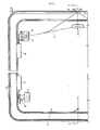
- Figure 1 is an inverted plan of a panel for a ventilator and window of a vehicle showing the layout of a panel release mechanism;
- Figure 2 is a section on the line 2-2 of Figure 1;
- Figure 3 is a section on the line 3-3 of Figure 1;
- Figure 4 is a section on the line 4-4 of Figure 1;
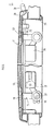
- Figure 5 is a plan substantially of one half of a panel release mechanism; and
- Figure 6 is a section on the line 6-6 of Figure 5.
- The ventilator or window illustrated in Figures 1 to 4 of the drawings comprises a panel 1 adapted to close an opening in the roof of vehicle, for example a passenger carrying coach. The opening is bounded by a fixed frame (not shown) which is fixed in the roof. The panel comprises an oblong
rectangular frame 12 having an inclined inwardly directedcontinuous lip 13, and asheet 14 of transparent or translucent plastics material which is held in theframe 12 by means of asealing strip 15. - The
panel 11 is carried from the frame by means of four arm assemblies which are arranged in pairs on opposite sides of the fixed frame. The arm assemblies are so constructed and arranged that the ventilator or window can be opened at either or both sides or ends to bring thepanel 11 into oppositely inclined positions or into a position parallel to and spaced from a closed position in which it engages with the fixed frame with thelip 13 overlying and surrounding a water check channel in the fixed frame. - As can best be seen in Figures 2 and 3, each arm assembly is connected to the
panel 11 by means of abracket 16 which comprises a pair ofcontinuous flanges flange 17 is connected to the inner face of theframe 12 of thepanel 11 by astud 19, and theflange 18 projects away from thepanel 11 for connection to a respective arm assembly. - Each
stud 19 comprises ahead 20 on the outside of theframe 12 and astem 21 projects through superimposed aligned openings in theframe 12 and theflange 17. Apin 22 projecting through atransverse hole 13 in thestem 21 detachably retains thebracket 16 in position. Acompression spring 24 is disposed between theflange 17 and awasher 25 which, in turn, acts on thepin 22 to prevent rattle and to bias thepin 22 against the wall of thehole 23, thereby avoiding accidental removal. - So that all four
pins 22 can be withdrawn simultaneously from theopenings 23 to permit the panelll to be jettisoned from the ventilator or window by disconnecting theflanges 17 from theframe 12, a flexibleinextensible member 26, suitably a cable, is trained around the interior of theframe 12, conveniently around rollers (not shown), which are disposed in opposite corners of theframe 12. Thecable 26 is connected to the corresponding ends of all fourpins 22, which ends all face in the same direction. At an intermediate location along its length, thecable 26 splits into twoportions portion manual release member release member radial groove 31. Thegroove 31 in theplug 29 serves detachably to retain theplug 29 in anopening 32 in amounting plate 33 which extends inwardly from theframe 12 and from which theplug 29 projects inwardly. Thegroove 31 in theplug 30 serves detachably to retain theplug 30 in an opening 34 in thelip 13 from which theplug 30 projects outwardly. Since both openings are above the level of water check channel in the frame which defines the opening, sealing difficulties are eliminated. - The
panel 11 can be removed from the window or ventilator, either from the interior or the exterior of the vehicle, by removing either theplug 29 or theplug 30 from its mounting and then withdrawing thecable 26 through therespective opening pins 22 simultaneously so that thepanel 11 can separate from thebrackets 16. Eachplug - In the modified ventilator or window illustrated in Figures 5 and 6
reference numeral 35 has been applied to the fixed frame surrounding the opening and a pair of front and rear arm assemblies on one side of theframe 25 are designated.36 and 37. Otherwise equivalent parts to those of the ventilator illustrated in Figures 1 to 4 are denoted by the same reference numerals. - The
bracket 16 of eachrear arm assembly 37 is fixedly secured to theframe 12. Theflange 18 of each of those two' brackets includes anelongate slot 38 in which apivotal connection 39 forming part of that arm assembly is pivotally and slidably received. The end of theslot 38 which is remote from thefront arm assembly 36 is open so that thebracket 16 of the rear arm assembly can be detached automatically with thepanel 11 from the remainder of thatarm assembly 37, upon release of thebrackets 16 of thefront arm assemblies 36. - The
brackets 16 of thefront arm assemblies 36 are detachably mounted on theframe 12 by a pin withdrawal mechanism similar to that described above with reference to Figure 1 to 4. However, the construction is simplified by arranging for the twopins 22 to be directed towards each other on opposite sides of the opening. This reduces the length of thecable 26. In addition thesprings 24 are replaced byblocks 40 of rubber. - Instead of the
springs 24 of the ventilator shown in Figure 1 to 4 or therubber blocks 40 of the ventilator shown in figures 5 and 6, resilient means may be disposed between theheads 20 of thestuds 19 and theframe 12. With this arrangement, thestuds 19 are ejected when thepins 22 are removed. Consequently, the axes of the studs need not be parallel to the direction in whichpanel 11 separates from the vehicle roof. The resilient means must incorporate sealing means to ensure that the joints between theframe 12 and theheads 20 of thestuds 19 are weatherproof.
Claims (8)
Applications Claiming Priority (2)
| Application Number | Priority Date | Filing Date | Title |
|---|---|---|---|
| GB7917147 | 1979-05-17 | ||
| GB7917147 | 1979-05-17 |
Publications (2)
| Publication Number | Publication Date |
|---|---|
| EP0019024A1 true EP0019024A1 (en) | 1980-11-26 |
| EP0019024B1 EP0019024B1 (en) | 1983-04-13 |
Family
ID=10505218
Family Applications (1)
| Application Number | Title | Priority Date | Filing Date |
|---|---|---|---|
| EP79303043A Expired EP0019024B1 (en) | 1979-05-17 | 1979-12-24 | Ventilator-panels and windows for vehicles |
Country Status (8)
| Country | Link |
|---|---|
| EP (1) | EP0019024B1 (en) |
| AU (1) | AU5433680A (en) |
| CA (1) | CA1108460A (en) |
| DE (1) | DE2965239D1 (en) |
| DK (1) | DK25880A (en) |
| ES (1) | ES487499A1 (en) |
| FI (1) | FI800025A7 (en) |
| NO (1) | NO794335L (en) |
Cited By (8)
| Publication number | Priority date | Publication date | Assignee | Title |
|---|---|---|---|---|
| EP0094257A3 (en) * | 1982-05-12 | 1985-06-19 | Transpec, Inc. | Combined vent and escape hatch |
| EP0092411A3 (en) * | 1982-04-19 | 1985-06-19 | Transpec, Inc. | Combined vent and escape hatch |
| DE4009349A1 (en) * | 1990-03-23 | 1991-09-26 | Cleff Gmbh Carl Wilhelm | Releasable window for railway carriage - uses emergency handle attached to rope around frame |
| EP0451606A3 (en) * | 1990-04-12 | 1993-02-24 | Webasto Ag Fahrzeugtechnik | Vehicle roof, especially for lorries or busses |
| DE19521876A1 (en) * | 1995-06-16 | 1996-12-19 | Dynamit Nobel Ag | Unlocking device for a window, in particular for railway wagons, with a slide |
| DE19855355A1 (en) * | 1998-12-01 | 2000-06-15 | Frank Natho | System to assist emergency evacuation of railway carriage, railcar or omnibus, for example, by automatic removal of windows from wall mountings |
| DE102007019078A1 (en) * | 2007-03-07 | 2008-09-11 | Spheros Gmbh | Roof air conditioning system for a bus comprises a main part mounted on an edge of an emergency exit opening in the vehicle roof using a hinge arrangement |
| EP3915870A1 (en) | 2020-05-28 | 2021-12-01 | Airbus Helicopters | Device for releasing a panel of an aircraft and associated aircraft |
Families Citing this family (1)
| Publication number | Priority date | Publication date | Assignee | Title |
|---|---|---|---|---|
| AU611899B2 (en) * | 1987-05-06 | 1991-06-27 | Cherrybob Pty. Ltd. | Improvements in vehicle hatches |
Citations (3)
| Publication number | Priority date | Publication date | Assignee | Title |
|---|---|---|---|---|
| US3338609A (en) * | 1966-03-11 | 1967-08-29 | Mc Donnell Douglas Corp | Emergency opening latch |
| GB1100621A (en) * | 1965-04-20 | 1968-01-24 | Hallam Sleigh & Cheston Ltd | Improvements relating to escape hatches |
| FR2341726A1 (en) * | 1976-02-17 | 1977-09-16 | Klein Ets Georges | Escape hatch cover for boat or plane - has H-shaped beading between cover and aperture with retaining lips ripped off by handles in emergency |
-
1979
- 1979-12-21 CA CA342,479A patent/CA1108460A/en not_active Expired
- 1979-12-24 DE DE7979303043T patent/DE2965239D1/en not_active Expired
- 1979-12-24 EP EP79303043A patent/EP0019024B1/en not_active Expired
- 1979-12-28 NO NO794335A patent/NO794335L/en unknown
-
1980
- 1980-01-03 AU AU54336/80A patent/AU5433680A/en not_active Abandoned
- 1980-01-03 FI FI800025A patent/FI800025A7/en not_active Application Discontinuation
- 1980-01-07 ES ES487499A patent/ES487499A1/en not_active Expired
- 1980-01-22 DK DK25880A patent/DK25880A/en unknown
Patent Citations (3)
| Publication number | Priority date | Publication date | Assignee | Title |
|---|---|---|---|---|
| GB1100621A (en) * | 1965-04-20 | 1968-01-24 | Hallam Sleigh & Cheston Ltd | Improvements relating to escape hatches |
| US3338609A (en) * | 1966-03-11 | 1967-08-29 | Mc Donnell Douglas Corp | Emergency opening latch |
| FR2341726A1 (en) * | 1976-02-17 | 1977-09-16 | Klein Ets Georges | Escape hatch cover for boat or plane - has H-shaped beading between cover and aperture with retaining lips ripped off by handles in emergency |
Cited By (11)
| Publication number | Priority date | Publication date | Assignee | Title |
|---|---|---|---|---|
| EP0092411A3 (en) * | 1982-04-19 | 1985-06-19 | Transpec, Inc. | Combined vent and escape hatch |
| EP0094257A3 (en) * | 1982-05-12 | 1985-06-19 | Transpec, Inc. | Combined vent and escape hatch |
| DE4009349A1 (en) * | 1990-03-23 | 1991-09-26 | Cleff Gmbh Carl Wilhelm | Releasable window for railway carriage - uses emergency handle attached to rope around frame |
| EP0451606A3 (en) * | 1990-04-12 | 1993-02-24 | Webasto Ag Fahrzeugtechnik | Vehicle roof, especially for lorries or busses |
| DE19521876A1 (en) * | 1995-06-16 | 1996-12-19 | Dynamit Nobel Ag | Unlocking device for a window, in particular for railway wagons, with a slide |
| DE19855355A1 (en) * | 1998-12-01 | 2000-06-15 | Frank Natho | System to assist emergency evacuation of railway carriage, railcar or omnibus, for example, by automatic removal of windows from wall mountings |
| DE102007019078A1 (en) * | 2007-03-07 | 2008-09-11 | Spheros Gmbh | Roof air conditioning system for a bus comprises a main part mounted on an edge of an emergency exit opening in the vehicle roof using a hinge arrangement |
| DE102007019078B4 (en) * | 2007-03-07 | 2009-04-16 | Spheros Gmbh | Roof-mounted air conditioning |
| EP3915870A1 (en) | 2020-05-28 | 2021-12-01 | Airbus Helicopters | Device for releasing a panel of an aircraft and associated aircraft |
| FR3110892A1 (en) * | 2020-05-28 | 2021-12-03 | Airbus Helicopters | Device for releasing an aircraft panel and associated aircraft |
| US11554846B2 (en) * | 2020-05-28 | 2023-01-17 | Airbus Helicopters | Device for releasing an aircraft panel and associated aircraft |
Also Published As
| Publication number | Publication date |
|---|---|
| FI800025A7 (en) | 1981-01-01 |
| DE2965239D1 (en) | 1983-05-19 |
| NO794335L (en) | 1980-11-18 |
| AU5433680A (en) | 1980-11-20 |
| ES487499A1 (en) | 1980-09-16 |
| DK25880A (en) | 1980-11-18 |
| CA1108460A (en) | 1981-09-08 |
| EP0019024B1 (en) | 1983-04-13 |
Similar Documents
| Publication | Publication Date | Title |
|---|---|---|
| US4130966A (en) | Ventilator hatch assembly | |
| US5809706A (en) | Flush closure device for an opening in bodywork | |
| US5363595A (en) | Arrangement of a vehicle door with extendable window | |
| US3979148A (en) | Window frame apparatus for vehicles | |
| US4676293A (en) | Impact-resistant overhead door | |
| US4541595A (en) | Removable interior window unit for aircraft | |
| US4257632A (en) | Detachable latching device for closure panels | |
| US4743062A (en) | Vehicle door assembly | |
| CA1306181C (en) | High speed folding door | |
| CA2210627A1 (en) | Swivel-sliding door system for a vehicle | |
| US4484773A (en) | Detachable low-profile latch assembly for releasably hinged closure panels | |
| US4104825A (en) | Vent | |
| CA1108460A (en) | Ventilator and windows for vehicles | |
| CA1059184A (en) | Openable dual windshield arrangement for construction vehicles | |
| US4466644A (en) | Multi-positioning latch assembly | |
| US4226052A (en) | Disengageable hinge device for a removable vehicle roof panel | |
| US5011215A (en) | Escape door system | |
| US5346267A (en) | Latch for hinged panel | |
| ES255478U (en) | Ventilators and/or windows for vehicles. | |
| EP0049983B1 (en) | Latches for panels | |
| US4428155A (en) | Releasable hinge device for removable panels | |
| JPS6343824A (en) | Module door structure | |
| GB2055138A (en) | Improvements in ventilator and windows in vehicles | |
| DE4337752A1 (en) | Snap lock | |
| US3288200A (en) | Window screens for vehicles |
Legal Events
| Date | Code | Title | Description |
|---|---|---|---|
| PUAI | Public reference made under article 153(3) epc to a published international application that has entered the european phase |
Free format text: ORIGINAL CODE: 0009012 |
|
| AK | Designated contracting states |
Designated state(s): AT BE CH DE FR GB IT LU NL SE |
|
| 17P | Request for examination filed |
Effective date: 19801118 |
|
| GRAA | (expected) grant |
Free format text: ORIGINAL CODE: 0009210 |
|
| AK | Designated contracting states |
Designated state(s): DE FR GB |
|
| ET | Fr: translation filed | ||
| REF | Corresponds to: |
Ref document number: 2965239 Country of ref document: DE Date of ref document: 19830519 |
|
| RAP2 | Party data changed (patent owner data changed or rights of a patent transferred) |
Owner name: BRISTOL STREET MOTORS (HENDON) LIMITED |
|
| PLBE | No opposition filed within time limit |
Free format text: ORIGINAL CODE: 0009261 |
|
| STAA | Information on the status of an ep patent application or granted ep patent |
Free format text: STATUS: NO OPPOSITION FILED WITHIN TIME LIMIT |
|
| 26N | No opposition filed | ||
| PGFP | Annual fee paid to national office [announced via postgrant information from national office to epo] |
Ref country code: FR Payment date: 19841207 Year of fee payment: 6 |
|
| PGFP | Annual fee paid to national office [announced via postgrant information from national office to epo] |
Ref country code: DE Payment date: 19841215 Year of fee payment: 6 |
|
| GBPC | Gb: european patent ceased through non-payment of renewal fee | ||
| PG25 | Lapsed in a contracting state [announced via postgrant information from national office to epo] |
Ref country code: FR Free format text: LAPSE BECAUSE OF NON-PAYMENT OF DUE FEES Effective date: 19860829 |
|
| PG25 | Lapsed in a contracting state [announced via postgrant information from national office to epo] |
Ref country code: DE Effective date: 19860902 |
|
| REG | Reference to a national code |
Ref country code: FR Ref legal event code: ST |
|
| PG25 | Lapsed in a contracting state [announced via postgrant information from national office to epo] |
Ref country code: GB Effective date: 19881118 |