EP0018902A2 - Tower for supporting a windmill propeller - Google Patents
Tower for supporting a windmill propeller Download PDFInfo
- Publication number
- EP0018902A2 EP0018902A2 EP80400573A EP80400573A EP0018902A2 EP 0018902 A2 EP0018902 A2 EP 0018902A2 EP 80400573 A EP80400573 A EP 80400573A EP 80400573 A EP80400573 A EP 80400573A EP 0018902 A2 EP0018902 A2 EP 0018902A2
- Authority
- EP
- European Patent Office
- Prior art keywords
- tower
- propeller
- legs
- aft
- plane
- Prior art date
- Legal status (The legal status is an assumption and is not a legal conclusion. Google has not performed a legal analysis and makes no representation as to the accuracy of the status listed.)
- Withdrawn
Links
Images


Classifications
-
- E—FIXED CONSTRUCTIONS
- E04—BUILDING
- E04H—BUILDINGS OR LIKE STRUCTURES FOR PARTICULAR PURPOSES; SWIMMING OR SPLASH BATHS OR POOLS; MASTS; FENCING; TENTS OR CANOPIES, IN GENERAL
- E04H12/00—Towers; Masts or poles; Chimney stacks; Water-towers; Methods of erecting such structures
- E04H12/18—Towers; Masts or poles; Chimney stacks; Water-towers; Methods of erecting such structures movable or with movable sections, e.g. rotatable or telescopic
-
- E—FIXED CONSTRUCTIONS
- E04—BUILDING
- E04H—BUILDINGS OR LIKE STRUCTURES FOR PARTICULAR PURPOSES; SWIMMING OR SPLASH BATHS OR POOLS; MASTS; FENCING; TENTS OR CANOPIES, IN GENERAL
- E04H12/00—Towers; Masts or poles; Chimney stacks; Water-towers; Methods of erecting such structures
- E04H12/02—Structures made of specified materials
- E04H12/08—Structures made of specified materials of metal
- E04H12/10—Truss-like structures
-
- F—MECHANICAL ENGINEERING; LIGHTING; HEATING; WEAPONS; BLASTING
- F03—MACHINES OR ENGINES FOR LIQUIDS; WIND, SPRING, OR WEIGHT MOTORS; PRODUCING MECHANICAL POWER OR A REACTIVE PROPULSIVE THRUST, NOT OTHERWISE PROVIDED FOR
- F03D—WIND MOTORS
- F03D13/00—Assembly, mounting or commissioning of wind motors; Arrangements specially adapted for transporting wind motor components
- F03D13/20—Arrangements for mounting or supporting wind motors; Masts or towers for wind motors
-
- F—MECHANICAL ENGINEERING; LIGHTING; HEATING; WEAPONS; BLASTING
- F05—INDEXING SCHEMES RELATING TO ENGINES OR PUMPS IN VARIOUS SUBCLASSES OF CLASSES F01-F04
- F05B—INDEXING SCHEME RELATING TO WIND, SPRING, WEIGHT, INERTIA OR LIKE MOTORS, TO MACHINES OR ENGINES FOR LIQUIDS COVERED BY SUBCLASSES F03B, F03D AND F03G
- F05B2240/00—Components
- F05B2240/90—Mounting on supporting structures or systems
- F05B2240/91—Mounting on supporting structures or systems on a stationary structure
- F05B2240/912—Mounting on supporting structures or systems on a stationary structure on a tower
- F05B2240/9121—Mounting on supporting structures or systems on a stationary structure on a tower on a lattice tower
-
- Y—GENERAL TAGGING OF NEW TECHNOLOGICAL DEVELOPMENTS; GENERAL TAGGING OF CROSS-SECTIONAL TECHNOLOGIES SPANNING OVER SEVERAL SECTIONS OF THE IPC; TECHNICAL SUBJECTS COVERED BY FORMER USPC CROSS-REFERENCE ART COLLECTIONS [XRACs] AND DIGESTS
- Y02—TECHNOLOGIES OR APPLICATIONS FOR MITIGATION OR ADAPTATION AGAINST CLIMATE CHANGE
- Y02E—REDUCTION OF GREENHOUSE GAS [GHG] EMISSIONS, RELATED TO ENERGY GENERATION, TRANSMISSION OR DISTRIBUTION
- Y02E10/00—Energy generation through renewable energy sources
- Y02E10/70—Wind energy
- Y02E10/72—Wind turbines with rotation axis in wind direction
-
- Y—GENERAL TAGGING OF NEW TECHNOLOGICAL DEVELOPMENTS; GENERAL TAGGING OF CROSS-SECTIONAL TECHNOLOGIES SPANNING OVER SEVERAL SECTIONS OF THE IPC; TECHNICAL SUBJECTS COVERED BY FORMER USPC CROSS-REFERENCE ART COLLECTIONS [XRACs] AND DIGESTS
- Y02—TECHNOLOGIES OR APPLICATIONS FOR MITIGATION OR ADAPTATION AGAINST CLIMATE CHANGE
- Y02E—REDUCTION OF GREENHOUSE GAS [GHG] EMISSIONS, RELATED TO ENERGY GENERATION, TRANSMISSION OR DISTRIBUTION
- Y02E10/00—Energy generation through renewable energy sources
- Y02E10/70—Wind energy
- Y02E10/728—Onshore wind turbines
Definitions
- the present invention relates to a tower for supporting a windmill propeller.
- Windmills have been known since ancient titnes. They extract power from the wind and usually the power is used in driving pumps for irrigation or to supply electrical power in rural areas. With the recent increase in energy costs, the attractiveness of wind power has improved.
- a windmill tower can be damaged or even destroyed by excessively large resonant vibrations during high wind conditions.
- the propeller operates upwind of its tower. There are three primary forces acting on the tower when the propeller rotates upwind of the tower :
- the invention proposes a tower for supporting a windmill propeller for rotating in a plane forward of the tower, characterized in that it comprises a pair of fixed fore legs spaced apart at their bottoms and converging upwardly toward a first apex, and a fixed diagonal bracing strut having a bottom spaced aft of the bottoms of the fore legs, with respect to the plane of rotation of propeller, and extending diagonally upwardly toward said apex, the fore legs and the diagonal bracing strut having top portions in the vicinity of said apex spaced aft of the plane of propeller rotation ; a pair of fixed aft legs having top portions spaced aft of said first apex, with respect to the plane of rotation of propeller, and extending downwardly adjacent opposite sides of the diagonal bracing strut, the aft legs being braced in a fixed position relative to the fore legs ; load support means secured to the top portions'of the fore legs and
- the fore legs and diagonal bracing strut being rigidly secured to a rigid base plane structure, aid in providing a stiff tower with a high natural frequency.
- the natural frequency of the tower can be lower than the passing frequency of rotating propeller blades of a propeller mounted atop the tower. This can significantly reduce resonant vibrations in the tower.
- the diagonal bracing strut is a compressive member that resists thrust loading on the tower which adds to the stiffness of the tower.
- the aft legs cooperate with the fore legs to resist torsional moments in a horizontal plane at the top of the tower. This also adds to the stiffness of the tower in providing its low natural frequency and attendant resistance to resonant vibrations.
- the present invention provides a windmill tower that can adapt well to varying wind conditions and can withstand high wind forces. As a result, the windmill can be used for large scale power generation.
- the windmill tower and propeller described in that application are large by windmill standards.
- the wind turbine will produce a rated three million watts of power in a 65 Km/h wind. It includes a 3-bladed upwind propeller with a diameter of 50 meters that will stand nearly 60 meters tall at the point of the highest blade rotation.
- the tower for supporting the rotor is mounted on a concrete and steel base.
- the entire tower structure and propeller pivot relative to the base as the propeller maintains a position upwind of the tower.
- the rotatable tower makes it possible to use a large propeller that, in turn, generates a large amount of power.
- the tower In most windmills the tower is fixed and the propeller pivots relative to the tower with changes in wind direction.
- the fixed tower should have a relatively wide base for properly supporting the weight of the propeller and its attendant rotating machinery. If the propeller pivots relative to a fixed tower, and if the tower has a wide base, the propeller blades are usually relatively short to avoid contact with the tower as the propeller changes direction with the wind. Silo towers also have been used, but they generally experience resonance problems and therefore have not proved suitable for large scale power generation applications.
- the rotatable tower of this invention is a wide base structure that supports the propeller blades at the side of the tower. Since the tower and propeller pivot together with changes in wind direction, the propeller blades do not contact the tower, and therefore long propeller blades can be used.
- a windmill includes an upright tower 10 supporting a platform 12 in a horizontal position above the tower.
- the platform is rigidly affixed to the top of the tower.
- a propeller 14 is supported on the tower adjacent the platform.
- the propeller has three radially extending blades 16 spaced apart equidistantly about a horizontal axis of rotation 17 illustrated in phantom lines in Figure 2.
- the propeller includes a variable pitch propeller hub cowling 18 capped by a stremlined nose 20.
- a root fairing 22 for each propeller blade couples into the hub.
- the propeller blades extend in a vertical plane adjacent the side of the tower, and the blades are relatively long, extending for a major portion of the height of the tower.
- the propeller is coupled to rotating machinery supported on the platform 12.
- a skin 24 encompasses portions of a generator system, propeller feather control components, and associated framework, all mounted on the platform. 9
- the tower is mounted on a flat base 26.
- a circular track 28 at the periphery of the base guides the path of the tower as it rotates about a vertical axis through a pivot 30.
- Rollers 31 support the bottom of the ] tower for rotation on the base.
- the propeller blades rotate about the horizontal axis 17 in response to the wind acting on the propeller. As the propeller rotates about its axis, the entire tower rotates about the vertical axis through the pivot 30 to constantly maintain the propeller upwind of the tower.
- the tower comprises a family of structural beams secured together as a rigid upright structure.
- Main structural members of the tower include a pair of upwardly converging fore legs 32 on a front side of the tower immediately aft of the propeller.
- the front side of the tower is defined with reference to the portion of the tower closest to the propeller, while a rear or aft side of the tower is that portion located farthest from the propeller.
- the bottoms of the fore legs are spaced apart on opposite sides of the propeller, and the bottoms of the fore legs are in a horizontal base plane 33. (see Figure 2) at the bottom of the tower.
- the fore legs proceed upwardly from the base plane, tapering closer together and intersecting at a first apex 34 immediately aft to the propeller on the propeller axis of rotation 17.
- the fore legs when viewed from the front side of the tower as in Figure 3, are symmetrical about a vertical axis 36 through the first apex 34 and the propeller axis of rotation 17.
- the propeller extends generally in a vertical plane 38 spaced forward from the front side of the tower.
- the bottoms of the fore legs are aligned on an axis that extends generally parallel to the vertical plane 38 in which the propeller rotates.
- the bottoms of the fore legs are spaced farther from the vertical plane of the propeller than the tops of the fore legs.
- the fore legs extend diagonally forward and upward from the base plane 33 toward the plane 38 of the propeller.
- the fore legs extend upwardly from the base plane at an acute angle of about 83°.
- the plane of the fore legs intersects the vertical plane 38 of the propeller at a point spaced above the horizontal axis of rotation 17 of the propeller.
- a diagonal bracing strut 40 extends downwardly and rearwardly from the first apex 34 away from the fore legs to the base plane of the truss.
- the bottom of the diagonal bracing strut is spaced aft of the bottoms of the fore legs, and the bottoms of the three members.are tied together as a rigid unit in a triangular horizontal base plane truss frame 42 described below.
- the top of the diagonal bracing strut is spaced a short distance aft of the tops of the fore legs. The tops of these three members support the bottom of the platform 12.
- the tops of the fore legs are spaced a short distance apart where they support the front of the platform.
- the axis of the diagonal bracing strut intersects the axes of the fore legs at the first apex 34, i.e., at the axis 17 of rotation of the propeller.
- the tops of the three members are rigidly secured together by the rigid platform structure.
- the diagonal bracing strut tapers away from the fore legs along an axis that is equidistantly spaced from each fore leg.
- the diagonal bracing strut is symmetrical with respect to the fore legs and extends along a vertical plane through the vertical axis 36 passing through the first apex.
- the diagonal bracing strut extends upwardly from the base plane at an angle of about 53°.
- a pair of upwardly converging aft legs 44 extend diagonally upward in an aft direction from the bottom of the fore legs.
- the aft legs intersect at a second apex 46 spaced aft of the first apex.
- the second apex is on the horizontal axis of rotation 17 of the propeller.
- the tops of the aft legs support the aft end of the platform.
- the upward convergence of the aft legs is symmetrical with respect to the vertical axis 36 through the first and second apexes 34 and 46.
- the aft legs thus extend diagonally upwardly generally at the same angle of convergence as the fore legs.
- the fore legs When the tower is viewed from the side in Figure 2, the fore legs extend diagonally upwardly from the base plane at an obtuse angle of about 106°.
- the tops of the aft legs are spaced apart by a short distance and are rigidly secured together by the rigid platform structure.
- the base plane truss frame 42 includes three peripheral beams rigidly interconnected at their ends to form the periphery of a rigid triangular be plane truss frame.
- the bottoms of the fore legs 32 are rigidly secured to the front corners of the peripheral base plane truss frame.
- the bottom of the diagonal bracing strut is rigidly affixed to a rear corner of the base plane truss frame.
- the three peripheral beams of the base plane truss lie in a horizontal plane at the bottom of the tower and they include a front peripheral beam 48 extending across the front of the base plane truss paral to the vertical plane in which the propeller rotates.
- a pair of rearwardly converging side peripheral beams 50 extend horizontally from the bottoms of the fore legs along opposite sides of the base plane truss, converging at a rear corner of the base plane truss.
- the three peripheral beams thus form a rigid triangular peripheral frame that stiffens the bottoms of the fore legs and the diagonal bracing strut at the base of the tower.
- the tower primarily includes a rigid front truss frame, and a pai of rigid side truss frames that converge in an aft direction away from the propeller and away from opposite sides of the front truss frame.
- Each of th three truss frames is generally upright and converges toward a common apex aft of the propeller and preferably on the propeller axis of rotation.
- the . bottoms of the three truss frames are rigidly tied together by a rigid triangular base plane truss.
- the three truss frames are rigidly interconnected as a rigid upright structure.
- Main upright load-taking members of the truss frames include the fore legs, which are rigidly secured at their bottoms to the front corners of the base plane truss frame, and the diagoneal bracing strut, which is rigidly secured at its bottom to the rear corner of the base plane truss frame.
- the aft legs cooperate with the fore legs to form a pair of inverted triangular truss frames outboard of the primary side truss frames of the tower.
- the aft legs cooperate with each other to form a rigid triangular truss frame extending downwardly from the aft end of the platform.
- the bottoms of the aft legs 44 are secured to the base plane truss flame 42 by rigidly affixing them to the side peripheral beams 50 immediately aft of the fore legs.
- the peripheral beams of the base plane truss are stiffened by cross-bracing which includes an intermediate cross-brace 52 extending between midpoints of the peripheral side beams 50.
- a pair of parallel cross-braces 54 extend in an aft direction from intermediate points on the front peripheral beam 48 to the intermediate cross-brace 52.
- a pair of rearwardly converging diagonal braces 56 extend from the front corners of the base plane truss 42 to the parallel cross-braces 56.
- a long rear cross-brace 58 extends from the rear corner of the base plane truss 42 to the middle of the intermediate cross-brace 52.
- a pair of shorter rear cross-braces 60 extend parallel to and along opposite sides of the rear cross-brace 58.
- Parallel cross-braces 62 extend away from opposite sides of each diagonal brace 56 to the front peripheral beam 48 and to the intermediate cross-brace 52.
- Parallel cross-braces 64 and 66 extend away from opposite sides of each diagonal brace to the front peripheral beam and to the middle of the side peripheral beams 50.
- the central pivot 30 is rigidly interconnected with the rest of the tower through radial beams 68 extending radially outwardly from the pivot 30 to the corners of the base plane truss 42.
- the radial beams 68 extend upwardly at a shallow angle from the corners of the truss 42 toward locations on the pivot 30 elevated a short distance above the plane 33 of the base plane truss 42.
- the pivot 30 includes a central upright axle-receiving post 70 and an axle anchored to ground received in the post.
- the base plane truss 42 and its cross-bracing can provide a means of support for equipment such as a generator machine room (not shown).
- FIG. 5 illustrates a lower level horizontal truss frame 71 immediately above the base plane truss 42.
- the lower horizontal truss frame 71 includes a front peripheral beam 72 rigidly affixed at its ends to sides of the fore legs 32, and a pair of rearwardly converging side peripheral beams 74 rigidly affixed at their front ends to the fore legs and rigidly affixed at their aft ends to the diagonal bracing strut 40.
- the peripheral beams of the lower truss frame 71 are stiffened by a secondary truss having two rearwardly diverging frame members 76 extending from the middle of the front peripheral beam 72 to the middles of the side peripheral beams 74.
- the secondary truss also includes an intermediate cross-member 78 extending parallel to the front peripheral beam 72 beween the middles of the side peripheral beams 74.
- Figure 6 illustrates an intermediate level horizontal truss frame 75 which includes a front peripheral beam 80 rigidly affixed at its ends to sides of the fore legs 32 and a pair of rearwardly converging side peripher.
- beams 82 rigidly affixed at their front ends to the fore legs and at their aft ends to the diagonal bracing strut 40.
- Separate long diagonal cross-braces 84 and a corresponding short diagonal cross-braces 85 extend collinet ly from each fore leg 32 across to the aft leg 44 on the opposite side of the tower.
- the long diagonal cross-braces intersect and are rigidly securec to each other at an X-shaped joint aft of the front peripheral beam 80.
- the adjacent ends of the long and short diagonal cross-braces are rigidly affixe to opposite sides of the side peripheral beams 82.
- the fore and aft legs are stiffened by a pair of short peripheral braces 86 extending aft from the fore legs to the sides of the aft legs.
- Figure 7 illustrates an upper level horizontal stiffening truss frame 87 spaced immediately below the platform 12.
- This truss frame includes a front peripheral beam 88 extending between sides of the fore legs and a pair of rearwardly converging diagonal side beams 90 extending from the fore legs to the diagonal bracing truss 40.
- An intermediate cross-brace 92 extends' aft from the middle of the front peripheral beam 80 to the diagonal bracing truss at the same joint where the diagonal side beams 90 are rigidly affixed.
- Horizontal outer stiffening trusses stiffen each aft leg with respect to an adjacent fore leg and the diagonal bracing truss.
- Each outer stiffening truss includes a rearwardly extending side peripheral beam 94 extending from a fore leg to an adjacent aft leg, and a rear peripheral beam 96 extending from each aft leg to a side of the diagonal bracing strut at the same joint where the diagonal side beams 90 and the intermediate cross-brace 92 are rigidly secured.
- Each diagonal side beam 90 comprises a separate member of each horizontal outer stiffening truss.
- the fore and aft legs (32, 44) are stiffened above the plane of the uppeI horizontal truss frame 87 by a pair of converging side beams 98 extending upwardly and rearwardly from the fore legs 32, in the plane of the upper horizontal truss frame 87, to the tops of the aft legs 44.
- the tops of the converging side beams 98 are rigidly affixed to sides of the aft legs 44 immediately adjacent the bottom of the platform 12.
- the fore legs 32 and the diagonal bracing strut 40 are stiffened between the planes of the intermediate and upper horizontal truss frames 75, 87 by a pair of diagonal beams 100 converging upwardly and rearwardly from the fore legs 32, in the plane of the intermediate horizontal truss frame 75, to the diagonal bracing strut 40 in the plane of the upper horizontal truss frame 87.
- the fore legs 32 are stiffened relative to the upper horizontal intermediate truss frame 87 by a generally upright truss frame which includes a pair of front truss members 102 converging upwardly from the fore legs 32, at their juncture with the ends of the front peripheral beam 80, to the middle of the front peripheral beam 88.
- the fore legs 32 are also stiffened relative to the lower horizontal truss frame 71 by a generally upright truss frame which includes a pair of front truss members 104 converging downwardly from the fore legs, at their juncture with the ends of the front peripheral beam 80, to the middle of the front peripheral beam 72.
- the fore legs 32 are"also stiffened relative to the lower horizontal truss frame 71 by a pair of generally upright side truss frame each including a first diagonal truss member 106 extending rearwardly and downwardly from the fore leg, at its juncture with the side peripheral beam 82, to the middle of the side peripheral beam 74 ; and a second diagonal truss member 108 extending forward and downwardly from the diagonal bracing strut, at its juncture with the side peripheral beam 82, to the middle of the side peripheral beam 74.
- the fore legs are stiffened relative to the base plane truss 42 by a generally upright front truss frame which includes a pair of front truss members 110 converging downwardly from the fore legs, at their juncture with the ends of the front peripheral beam 72, to the middle of the front peripheral beam 48 of the base plane truss.
- the fore legs and the diagonal bracing strut are stiffened with respect to the base plane truss by a pair of side truss frames each including a first truss member 112 extending downwardly and rearwardly from the fore leg, at the joint where the peripheral side beam 74 is connected, to the middle of the base plane peripheral side beam 50 ; and a second truss frame member 114 extending forward and downwardly from the opposite end of the peripheral beam 74 to the middle of the base plane side peripheral beam 50 .
- the tower consists primarily of straight load-taking tubular steel members.
- the fore legs 32 comprise 65 cm diameter tubing approximately 30 meters long with a wall thickness of approximately 3 cm.
- the diagonal bracing strut 40 comprises 65 cm. diameter tubing approximately 42 meters long with a wall thickness of approximately 3 cm.
- the aft legs 44 are 34 cm. diameter tubing approximately 30 meters long with a wall thickness of about 8 mm.
- the front peripheral beam 48 of the base plane truss 42 comprises 65 cm. diameter tubing approximately 20 meters long with a wall thickness of about 3 cm.
- the side peripheral beams 50 of the base plane truss also comprise 65cm. diameter tubing with a wall thickness of about 3 cm and are about 22 meters.
- Figure 8 illustrates a presently preferred means for forming a joint of a typical horizontal truss frame.
- the ends of the tubular members 76 and 78 are slotted and a separate 12 mm/ thick splice plate 116 is fitted into the slotted end of each pipe and welded to the pipe.
- a 2,5 cm. thick gusset plate 118 is welded to a side of the tubular member 74 at the point where the joint is being formed.
- the splice plates overlie the busset plate and the splice plates are fastened to the gusset plate by bolts 120.
- the splice plates nest in each tubular member by a distance equal to the nominal diameter of the pipe.
- a cyclic thrust loading acts on the tower as the propeller blades rotate past the tower.
- the propellE blades are upwind of the tower since the tower is able to rotate about the pivot with changes in wind direction.
- an exciting force acts on the tower due to the propeller blades reaction with the wind.
- the thrust force of the wind against the propeller blades produces cyclic thrust loading on the tower that also, in effect, pushes and pulls on the tower.
- rotation of the propeller shaft together with operation of rotating machinery on the platform and horizontal movements of the air combine to produce cyclic torsional loading in a horizontal plane at the top of the tower.
- the tower has a high natural frequency because of its stiffness which is produced in party by the bottoms of the main load-taking beams,i.e., the fore legs and the diagonal bracing strut, being rigidly affixed to a rigid base plane truss frame.
- the tower also has a wide base, i.e., the three main load-taking beams converge upwardly from a base having a greater area than the tower has at elevations above the base plane.
- the height of the tower also is not more than twice the length of any of the peripheral beams in the base plane truss frame, which provides a wide base relative to the height of the tower.
- the three main load-taking beams also converge together at an apex which they are rigidly secured together at the top of the tower.
- This configuration in effect, provides three rigid truss frames in generally upright planes along the three sides of the tower which adds stiffness to the tower structure.
- the combination of the three main load-taking beams being tied together in a rigid base plane, together with the tower having a wide base and the three main beams converging to an apex produces a stiff tower with a low natural frequency.
- the natural period of the tower is 0.3 second which is lower than the 0.49 second passing frequency of each propeller blade. Since the natural frequency of the tower is higher that the first mode passing frequency of the propeller blades, the stiffness of the tower considerably reduces resonant vibrations in the tower caused by cyclic thrust loading due to rotation of the propeller blades.
- the rigid diagonal bracing strut acts as a compressive member to support thrust loading on the tower. Since the tower is free to rotate about its base and since all three main load-taking beams are rigidly tied together in the base plane, the diagonal bracing strut resists essentially all of the thrust loading on the tower.
- tops of the two independent aft legs are spaced as far as practical from the tie point at the tops of the fore legs.
- the tops of the aft legs and the fore legs are rigidly stiffened relative to one another owing to their rigid connection to the tower platform.
- the aft legs cooperate with the fore legs to resist torsional moments in a horizontal plane at the top of the tower.
- the fore legs also act as compressive members to support the entire weight of the propeller and the tower rotating machinery load on the tower platform.
- the tower is readily scaleable up to large heights, say over 30 meters in height, while maintaining a high degree of required rigidity.
Abstract
A tower for supporting a windmill propeller (14) for rotating in a plane forward of the tower, comprising a pair of fixed fore legs (32) spaced apart at their bottoms and converging upwardlytoward a first apex (34), and a fixed diagonal bracing strut (40) having a bottom spaced aft of the bottoms of the fore legs, with respect to the plane of rotation (38) of propeller (14), and extending diagonally upwardly toward said apex, the fore legs and the diagonal bracing strut having top portions in the vicinity of said apex spaced aft of the plane of propeller rotation : a pair offixed aft legs (44) having top portions spaced aft of said first apex (34). with respect to the plane of rotation (38) of propeller (14), and extending downwardly adjacent opposite sides of the diagonal bracing strut (40). the aft (44) legs being braced in a fixed position relative to the fore legs (32) ; load support means (12) secured to the top portions of the fore legs (32) and the diagonal bracing strut (40) and the aft legs (44) for supporting a load from the propeller (14); and means (42) rigidly enterconnecting the bottoms of the fore legs (32) and the bottom of the diagonal bracing strut (40) at a base (33) of the tower.
Description
- The present invention relates to a tower for supporting a windmill propeller.
- Windmills have been known since ancient titnes. They extract power from the wind and usually the power is used in driving pumps for irrigation or to supply electrical power in rural areas. With the recent increase in energy costs, the attractiveness of wind power has improved.
- Recently, consideration has been given to using wind power generators to supply electrical energy for utilities as an alternative to conventional electrical generation plants, hopefully to reduce the amount of costly fuel oil which is now used. However, windmills capable of generating sufficient power to provide a meaningful alternative source of energy are faced with a host of problems.
- A considerable amount of power exists in wind at high speeds. It can be desirable to locate wind mills used for commercial power generation in areas having high wind speeds in order to maximize power generation output.
- A windmill tower can be damaged or even destroyed by excessively large resonant vibrations during high wind conditions. In the windmill of this invention, the propeller operates upwind of its tower. There are three primary forces acting on the tower when the propeller rotates upwind of the tower :
- - As the blades of the rotating propeller pass the tower, the tower is cyclically excited by a cyclic thrust loading which tends to push and pull on the tower ;
- - the cyclic thrust force of the wind against the propeller blades during varying wind conditions also tends to push and pull on the tower :
- - the tower is subject to cyclic torque loading from the rotating propeller, rotating machinery, and horizontal movement of the wind which produces a twisting or torsional moment in a horizontal plane on the top of the tower.
- It is an object of the present invention to provide a windmill tower structure having a stiffness that resists cyclic thrust and torque loading on the tower sufficiently to reduce resonant vibrations of the tower to an extent that the tower can safely support the propeller under high wind conditions while generating sufficient electrical power for electrical utility purposes.
- To this end the invention proposes a tower for supporting a windmill propeller for rotating in a plane forward of the tower, characterized in that it comprises a pair of fixed fore legs spaced apart at their bottoms and converging upwardly toward a first apex, and a fixed diagonal bracing strut having a bottom spaced aft of the bottoms of the fore legs, with respect to the plane of rotation of propeller, and extending diagonally upwardly toward said apex, the fore legs and the diagonal bracing strut having top portions in the vicinity of said apex spaced aft of the plane of propeller rotation ; a pair of fixed aft legs having top portions spaced aft of said first apex, with respect to the plane of rotation of propeller, and extending downwardly adjacent opposite sides of the diagonal bracing strut, the aft legs being braced in a fixed position relative to the fore legs ; load support means secured to the top portions'of the fore legs and the diagonal bracing strut and the aft legs for supporting a load from the propeller ; and means rigidly interconnecting the bottoms of the fore legs and the bottom of the diagonal bracing strut at a base of the tower.
- The fore legs and diagonal bracing strut, being rigidly secured to a rigid base plane structure, aid in providing a stiff tower with a high natural frequency. The natural frequency of the tower can be lower than the passing frequency of rotating propeller blades of a propeller mounted atop the tower. This can significantly reduce resonant vibrations in the tower. The diagonal bracing strut is a compressive member that resists thrust loading on the tower which adds to the stiffness of the tower. The aft legs cooperate with the fore legs to resist torsional moments in a horizontal plane at the top of the tower. This also adds to the stiffness of the tower in providing its low natural frequency and attendant resistance to resonant vibrations.
- These and other aspects of the invention will be more fully understood by referring to the detailed description and the accompanying drawings.
- The present invention provides a windmill tower that can adapt well to varying wind conditions and can withstand high wind forces. As a result, the windmill can be used for large scale power generation. The windmill tower and propeller described in that application are large by windmill standards. The wind turbine will produce a rated three million watts of power in a 65 Km/h wind. It includes a 3-bladed upwind propeller with a diameter of 50 meters that will stand nearly 60 meters tall at the point of the highest blade rotation. The tower for supporting the rotor is mounted on a concrete and steel base.
- According to another aspect of the invention the entire tower structure and propeller pivot relative to the base as the propeller maintains a position upwind of the tower.
- The rotatable tower makes it possible to use a large propeller that, in turn, generates a large amount of power. In most windmills the tower is fixed and the propeller pivots relative to the tower with changes in wind direction. The fixed tower should have a relatively wide base for properly supporting the weight of the propeller and its attendant rotating machinery. If the propeller pivots relative to a fixed tower, and if the tower has a wide base, the propeller blades are usually relatively short to avoid contact with the tower as the propeller changes direction with the wind. Silo towers also have been used, but they generally experience resonance problems and therefore have not proved suitable for large scale power generation applications. The rotatable tower of this invention is a wide base structure that supports the propeller blades at the side of the tower. Since the tower and propeller pivot together with changes in wind direction, the propeller blades do not contact the tower, and therefore long propeller blades can be used.
- The invention will now be described with reference to the accompanying drawings wherein :
- - Figure 1 is a semi-schematic perspective view illustrating a windmill tower according to principles of this invention ;
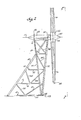
- - Figure 2 is a side elevation view of the windmill tower taken on line 2-2 of Figure 1 ;
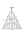
- - Figure 3 is a front elevation view of the tower taken on line 3-3 of Figure 2 ;
- -Figure 4 is a plan view of the tower base structure taken on line 4-4 of Figure 3 ;
- - Figure 5 is a plan view of the tower structure at an elevation taken on line 5-5 of Figure 3 ;
- - Figure 6 is a plan view of the tower structure at an elevation taken on line 6-6 of Figure 3 ;
- - Figure 7 is a plan view of the tower structure taken at an elevation on line 7-7 of Figure 3 ; and
- - Figure 8 is an enlarged fragmentary plan view illustrating a detailed construction of a typical joint in the tower structure.
- Referring to Figure 1, a windmill includes an upright tower 10 supporting a
platform 12 in a horizontal position above the tower. The platform is rigidly affixed to the top of the tower. Apropeller 14 is supported on the tower adjacent the platform. The propeller has three radially extendingblades 16 spaced apart equidistantly about a horizontal axis ofrotation 17 illustrated in phantom lines in Figure 2. The propeller includes a variable pitch propeller hub cowling 18 capped by astremlined nose 20. Aroot fairing 22 for each propeller blade couples into the hub. The propeller blades extend in a vertical plane adjacent the side of the tower, and the blades are relatively long, extending for a major portion of the height of the tower. - The propeller is coupled to rotating machinery supported on the
platform 12. Askin 24 encompasses portions of a generator system, propeller feather control components, and associated framework, all mounted on the platform. 9 - The tower is mounted on a
flat base 26. Acircular track 28 at the periphery of the base guides the path of the tower as it rotates about a vertical axis through a pivot 30.Rollers 31 support the bottom of the ] tower for rotation on the base. The propeller blades rotate about thehorizontal axis 17 in response to the wind acting on the propeller. As the propeller rotates about its axis, the entire tower rotates about the vertical axis through the pivot 30 to constantly maintain the propeller upwind of the tower. - The tower comprises a family of structural beams secured together as a rigid upright structure. Main structural members of the tower include a pair of upwardly converging fore
legs 32 on a front side of the tower immediately aft of the propeller. The front side of the tower is defined with reference to the portion of the tower closest to the propeller, while a rear or aft side of the tower is that portion located farthest from the propeller. The bottoms of the fore legs are spaced apart on opposite sides of the propeller, and the bottoms of the fore legs are in ahorizontal base plane 33. (see Figure 2) at the bottom of the tower. The fore legs proceed upwardly from the base plane, tapering closer together and intersecting at afirst apex 34 immediately aft to the propeller on the propeller axis ofrotation 17. The fore legs, when viewed from the front side of the tower as in Figure 3, are symmetrical about avertical axis 36 through thefirst apex 34 and the propeller axis ofrotation 17. As illustrated best in Figure 2, the propeller extends generally in avertical plane 38 spaced forward from the front side of the tower. The bottoms of the fore legs are aligned on an axis that extends generally parallel to thevertical plane 38 in which the propeller rotates. The bottoms of the fore legs are spaced farther from the vertical plane of the propeller than the tops of the fore legs. As illustrated best in Figure 2, the fore legs extend diagonally forward and upward from thebase plane 33 toward theplane 38 of the propeller. The fore legs extend upwardly from the base plane at an acute angle of about 83°. The plane of the fore legs intersects thevertical plane 38 of the propeller at a point spaced above the horizontal axis ofrotation 17 of the propeller. - A diagonal bracing
strut 40 extends downwardly and rearwardly from thefirst apex 34 away from the fore legs to the base plane of the truss. The bottom of the diagonal bracing strut is spaced aft of the bottoms of the fore legs, and the bottoms of the three members.are tied together as a rigid unit in a triangular horizontal baseplane truss frame 42 described below. As shown best in Figure 2, the top of the diagonal bracing strut is spaced a short distance aft of the tops of the fore legs. The tops of these three members support the bottom of theplatform 12. The tops of the fore legs are spaced a short distance apart where they support the front of the platform., The axis of the diagonal bracing strut intersects the axes of the fore legs at thefirst apex 34, i.e., at theaxis 17 of rotation of the propeller. The tops of the three members are rigidly secured together by the rigid platform structure. The diagonal bracing strut tapers away from the fore legs along an axis that is equidistantly spaced from each fore leg. Thus, as the tower is viewed from the front in Figure 3, the diagonal bracing strut is symmetrical with respect to the fore legs and extends along a vertical plane through thevertical axis 36 passing through the first apex. In one embodiment, the diagonal bracing strut extends upwardly from the base plane at an angle of about 53°. - A pair of upwardly converging
aft legs 44 extend diagonally upward in an aft direction from the bottom of the fore legs. The aft legs intersect at asecond apex 46 spaced aft of the first apex. The second apex is on the horizontal axis ofrotation 17 of the propeller. The tops of the aft legs support the aft end of the platform. The upward convergence of the aft legs is symmetrical with respect to thevertical axis 36 through the first andsecond apexes - At regular vertical intervals, horizontal stiffening trusses add rigi to the beam system. Details of the
base plane truss 42 are shown inFigur 4, and Figures 5 through 7 illustrate horizontal stiffening trusses at respectively higher elevations.. - The base
plane truss frame 42 includes three peripheral beams rigidly interconnected at their ends to form the periphery of a rigid triangular be plane truss frame. The bottoms of thefore legs 32 are rigidly secured to the front corners of the peripheral base plane truss frame. The bottom of the diagonal bracing strut is rigidly affixed to a rear corner of the base plane truss frame. The three peripheral beams of the base plane truss lie in a horizontal plane at the bottom of the tower and they include a frontperipheral beam 48 extending across the front of the base plane truss paral to the vertical plane in which the propeller rotates. A pair of rearwardly converging sideperipheral beams 50 extend horizontally from the bottoms of the fore legs along opposite sides of the base plane truss, converging at a rear corner of the base plane truss. The three peripheral beams thus form a rigid triangular peripheral frame that stiffens the bottoms of the fore legs and the diagonal bracing strut at the base of the tower. - Thus, the tower primarily includes a rigid front truss frame, and a pai of rigid side truss frames that converge in an aft direction away from the propeller and away from opposite sides of the front truss frame. Each of th three truss frames is generally upright and converges toward a common apex aft of the propeller and preferably on the propeller axis of rotation. The . bottoms of the three truss frames are rigidly tied together by a rigid triangular base plane truss. The three truss frames are rigidly interconnected as a rigid upright structure. Main upright load-taking members of the truss frames include the fore legs, which are rigidly secured at their bottoms to the front corners of the base plane truss frame, and the diagoneal bracing strut, which is rigidly secured at its bottom to the rear corner of the base plane truss frame.
- The aft legs cooperate with the fore legs to form a pair of inverted triangular truss frames outboard of the primary side truss frames of the tower. The aft legs cooperate with each other to form a rigid triangular truss frame extending downwardly from the aft end of the platform. These truss frames resist torsional loading in a horizontal direction on the platform.
- The bottoms of the
aft legs 44 are secured to the baseplane truss flame 42 by rigidly affixing them to the sideperipheral beams 50 immediately aft of the fore legs. - The peripheral beams of the base plane truss are stiffened by cross-bracing which includes an
intermediate cross-brace 52 extending between midpoints of the peripheral side beams 50. A pair of parallel cross-braces 54 extend in an aft direction from intermediate points on the frontperipheral beam 48 to theintermediate cross-brace 52. A pair of rearwardly convergingdiagonal braces 56 extend from the front corners of thebase plane truss 42 to theparallel cross-braces 56. A long rear cross-brace 58 extends from the rear corner of thebase plane truss 42 to the middle of theintermediate cross-brace 52. A pair of shorterrear cross-braces 60 extend parallel to and along opposite sides of the rear cross-brace 58. Parallel cross-braces 62 extend away from opposite sides of eachdiagonal brace 56 to the frontperipheral beam 48 and to theintermediate cross-brace 52.Parallel cross-braces 64 and 66 extend away from opposite sides of each diagonal brace to the front peripheral beam and to the middle of the side peripheral beams 50. - The central pivot 30 is rigidly interconnected with the rest of the tower through radial beams 68 extending radially outwardly from the pivot 30 to the corners of the
base plane truss 42. The radial beams 68 extend upwardly at a shallow angle from the corners of thetruss 42 toward locations on the pivot 30 elevated a short distance above theplane 33 of thebase plane truss 42. The pivot 30 includes a central upright axle-receiving post 70 and an axle anchored to ground received in the post. Thebase plane truss 42 and its cross-bracing can provide a means of support for equipment such as a generator machine room (not shown). - Figure 5 illustrates a lower level horizontal truss frame 71 immediately above the
base plane truss 42. The lower horizontal truss frame 71 includes a frontperipheral beam 72 rigidly affixed at its ends to sides of thefore legs 32, and a pair of rearwardly converging sideperipheral beams 74 rigidly affixed at their front ends to the fore legs and rigidly affixed at their aft ends to the diagonal bracingstrut 40. The peripheral beams of the lower truss frame 71 are stiffened by a secondary truss having two rearwardly divergingframe members 76 extending from the middle of the frontperipheral beam 72 to the middles of the side peripheral beams 74. The secondary truss also includes anintermediate cross-member 78 extending parallel to the frontperipheral beam 72 beween the middles of the side peripheral beams 74. - Figure 6 illustrates an intermediate level horizontal truss frame 75 which includes a front
peripheral beam 80 rigidly affixed at its ends to sides of thefore legs 32 and a pair of rearwardly converging side peripher. beams 82 rigidly affixed at their front ends to the fore legs and at their aft ends to the diagonal bracingstrut 40. Separate long diagonal cross-braces 84 and a corresponding short diagonal cross-braces 85 extend collinet ly from eachfore leg 32 across to theaft leg 44 on the opposite side of the tower. The long diagonal cross-braces intersect and are rigidly securec to each other at an X-shaped joint aft of the frontperipheral beam 80. The adjacent ends of the long and short diagonal cross-braces are rigidly affixe to opposite sides of the side peripheral beams 82. The fore and aft legs are stiffened by a pair of shortperipheral braces 86 extending aft from the fore legs to the sides of the aft legs.- - Figure 7 illustrates an upper level horizontal
stiffening truss frame 87 spaced immediately below theplatform 12. This truss frame includes a frontperipheral beam 88 extending between sides of the fore legs and a pair of rearwardly converging diagonal side beams 90 extending from the fore legs to the diagonal bracingtruss 40. Anintermediate cross-brace 92 extends' aft from the middle of the frontperipheral beam 80 to the diagonal bracing truss at the same joint where the diagonal side beams 90 are rigidly affixed. Horizontal outer stiffening trusses stiffen each aft leg with respect to an adjacent fore leg and the diagonal bracing truss. Each outer stiffening truss includes a rearwardly extending sideperipheral beam 94 extending from a fore leg to an adjacent aft leg, and a rearperipheral beam 96 extending from each aft leg to a side of the diagonal bracing strut at the same joint where the diagonal side beams 90 and theintermediate cross-brace 92 are rigidly secured. Eachdiagonal side beam 90 comprises a separate member of each horizontal outer stiffening truss. - The fore and aft legs (32, 44) are stiffened above the plane of the uppeI
horizontal truss frame 87 by a pair of convergingside beams 98 extending upwardly and rearwardly from thefore legs 32, in the plane of the upperhorizontal truss frame 87, to the tops of theaft legs 44. The tops of the convergingside beams 98 are rigidly affixed to sides of theaft legs 44 immediately adjacent the bottom of theplatform 12. - The
fore legs 32 and the diagonal bracingstrut 40 are stiffened between the planes of the intermediate and upper horizontal truss frames 75, 87 by a pair ofdiagonal beams 100 converging upwardly and rearwardly from thefore legs 32, in the plane of the intermediate horizontal truss frame 75, to the diagonal bracingstrut 40 in the plane of the upperhorizontal truss frame 87. - The
fore legs 32 are stiffened relative to the upper horizontalintermediate truss frame 87 by a generally upright truss frame which includes a pair offront truss members 102 converging upwardly from thefore legs 32, at their juncture with the ends of the frontperipheral beam 80, to the middle of the frontperipheral beam 88. - The
fore legs 32 are also stiffened relative to the lower horizontal truss frame 71 by a generally upright truss frame which includes a pair offront truss members 104 converging downwardly from the fore legs, at their juncture with the ends of the frontperipheral beam 80, to the middle of the frontperipheral beam 72. Thefore legs 32 are"also stiffened relative to the lower horizontal truss frame 71 by a pair of generally upright side truss frame each including a firstdiagonal truss member 106 extending rearwardly and downwardly from the fore leg, at its juncture with the sideperipheral beam 82, to the middle of the sideperipheral beam 74 ; and a seconddiagonal truss member 108 extending forward and downwardly from the diagonal bracing strut, at its juncture with the sideperipheral beam 82, to the middle of the sideperipheral beam 74. - The fore legs are stiffened relative to the
base plane truss 42 by a generally upright front truss frame which includes a pair offront truss members 110 converging downwardly from the fore legs, at their juncture with the ends of the frontperipheral beam 72, to the middle of the frontperipheral beam 48 of the base plane truss. The fore legs and the diagonal bracing strut are stiffened with respect to the base plane truss by a pair of side truss frames each including afirst truss member 112 extending downwardly and rearwardly from the fore leg, at the joint where theperipheral side beam 74 is connected, to the middle of the base planeperipheral side beam 50 ; and a secondtruss frame member 114 extending forward and downwardly from the opposite end of theperipheral beam 74 to the middle of the base plane side peripheral beam 50. - The tower consists primarily of straight load-taking tubular steel members. In one embodiment, the
fore legs 32 comprise 65 cm diameter tubing approximately 30 meters long with a wall thickness of approximately 3 cm. The diagonal bracingstrut 40 comprises 65 cm. diameter tubing approximately 42 meters long with a wall thickness of approximately 3 cm. Theaft legs 44 are 34 cm. diameter tubing approximately 30 meters long with a wall thickness of about 8 mm. The frontperipheral beam 48 of thebase plane truss 42 comprises 65 cm. diameter tubing approximately 20 meters long with a wall thickness of about 3 cm. The sideperipheral beams 50 of the base plane truss also comprise 65cm. diameter tubing with a wall thickness of about 3 cm and are about 22 meters. - Figure 8 illustrates a presently preferred means for forming a joint of a typical horizontal truss frame. In the illustrated example, the ends of the
tubular members thick splice plate 116 is fitted into the slotted end of each pipe and welded to the pipe. A 2,5 cm.thick gusset plate 118 is welded to a side of thetubular member 74 at the point where the joint is being formed. The splice plates overlie the busset plate and the splice plates are fastened to the gusset plate bybolts 120. The splice plates nest in each tubular member by a distance equal to the nominal diameter of the pipe. - There are primarily three forces acting on the tower when the propeller rotates under the influence of the wind. First, a cyclic thrust loading acts on the tower as the propeller blades rotate past the tower. The propellE blades are upwind of the tower since the tower is able to rotate about the pivot with changes in wind direction. Each time a propeller blade passes the tower; an exciting force acts on the tower due to the propeller blades reaction with the wind. This produces a cyclic horizontal thrust loading that, in effect, pushes and pulls on the tower. Second, the thrust force of the wind against the propeller blades produces cyclic thrust loading on the tower that also, in effect, pushes and pulls on the tower. Third, rotation of the propeller shaft together with operation of rotating machinery on the platform and horizontal movements of the air combine to produce cyclic torsional loading in a horizontal plane at the top of the tower. r
- The tower has a high natural frequency because of its stiffness which is produced in party by the bottoms of the main load-taking beams,i.e., the fore legs and the diagonal bracing strut, being rigidly affixed to a rigid base plane truss frame. The tower also has a wide base, i.e., the three main load-taking beams converge upwardly from a base having a greater area than the tower has at elevations above the base plane. The height of the tower also is not more than twice the length of any of the peripheral beams in the base plane truss frame, which provides a wide base relative to the height of the tower. The three main load-taking beams also converge together at an apex which they are rigidly secured together at the top of the tower. This configuration, in effect, provides three rigid truss frames in generally upright planes along the three sides of the tower which adds stiffness to the tower structure.
- The combination of the three main load-taking beams being tied together in a rigid base plane, together with the tower having a wide base and the three main beams converging to an apex produces a stiff tower with a low natural frequency. In one embodiment the natural period of the tower is 0.3 second which is lower than the 0.49 second passing frequency of each propeller blade. Since the natural frequency of the tower is higher that the first mode passing frequency of the propeller blades, the stiffness of the tower considerably reduces resonant vibrations in the tower caused by cyclic thrust loading due to rotation of the propeller blades.
- The rigid diagonal bracing strut acts as a compressive member to support thrust loading on the tower. Since the tower is free to rotate about its base and since all three main load-taking beams are rigidly tied together in the base plane, the diagonal bracing strut resists essentially all of the thrust loading on the tower.
- The tops of the two independent aft legs are spaced as far as practical from the tie point at the tops of the fore legs. The tops of the aft legs and the fore legs are rigidly stiffened relative to one another owing to their rigid connection to the tower platform. The aft legs cooperate with the fore legs to resist torsional moments in a horizontal plane at the top of the tower.
- The fore legs also act as compressive members to support the entire weight of the propeller and the tower rotating machinery load on the tower platform.
- The tower is readily scaleable up to large heights, say over 30 meters in height, while maintaining a high degree of required rigidity.
Claims (16)
1. A tower for supporting a windmill propeller (14) for rotating in a plane forward of the tower, characterized in that it comprises a pair of fixed fore legs (32) spaced apart at their bottoms and concerning upwardly toward a first apex (34), and a fixed diagonal bracing strut (40) having a bottom spaced aft of the bottoms of the fore legs, with respect to the plal of rotation (38) of propeller (14), and extending diagonally upwardly towal said apex, the fore legs and the diagonal bracing strut having top portions in the vicinity of said apex spaced aft of the plane of propeller rotation a pair of fixed aft legs (44) having top portions spaced aft of said first apex (34), with respect to the plane of rotation (38) of propeller (14), ar extending downwardly adjacent opposite sides of the diagonal bracing strut (40), the aft (44) legs being braced in a fixed position relative to the fc legs (32) ; load support means (12) secured to the top portions of the fore legs (32) and the diagonal bracing strut (40) and the aft legs (44) for supporting a load from the propeller (14) ; and means (42) rigidly intercon necting the bottoms of the fore legs (32) and the bottom of the diagonal bracing strut (40) at a base (33) of the tower.
2. A tower according to claim 1, characterized in that the fore legs ( and the diagonal bracing strut (40) converge upwardly toward said firsf ape (34), and the aft legs (44) covnerge upwardly toward a second apex (46) spal aft of the first apex (34) with respect to the plane (38) of the propeller (14).
3. A tower according to claim 2, characterized in that it comprises means (87, 98) rigidly interconnecting the top portions of the aft legs (44 and the top portions of the fore legs (32) and the diagonal bracing strut (40).
4. A tower according to claim 3, characterized in that each aft leg 44 and a corresponding fore leg (32) converge downwardly toward a separate thii apex.
5. A tower according to claim 4, characterized in that each third apex is generally in a base plane (33) of the tower.
6. A tower according to any of claims 2 to 5, characterized in that the first and second apexes (34, 46) are on a substantially horizontal axis (117
7. A tower according to claim 6, characterized in that the load support means comprises a platform (12) supporting at least a portion of the propeller (14).
8. A tower according to claim 7, characterized in that said horizontal (17) axis is above the platform (12), and the propeller (14) is rotatable about the horizontal axis (17).
9. A tower according to any of the preceding claims, characterized in that the fore legs (32) are in a common plane extending diagonally upwardly toward a vertical plane (38) in which the propeller rotates, the bottoms of the fore legs (32) being aft of said apex (34) , with respect to the plane (38) of rotation of propeller (14).
10. A tower according to claim 9, characterized in that the aft legs (44) are rigidly secured at respective joints with the bottoms of correspon' ing fore legs (32), and the aft legs (44) are in a common plane extending diagonally upwardly away from the bottoms of the aft legs (44).
11. A tower according to any of the preceding claims, characterized in that the means rigidly interconnecting the bottoms of the fore legs (32) and the diagonal bracing strut (40) comprises a rigid triangular base plane truss frame (42).
12. A tower according to claim 11, characterized in that it comprises means rigidly securing the bottoms of each fore leg and associated aft leg to a corresponding front corner of the triangular base plane truss frame.
13. A tower according to claim 12, characterized in that the base plan truss frame (42) has a rear corner aft of the front corners, with respect t the plane (38) of the propeller, and the bottom of the diagonal bracing strut (40) is rigidly secured to said rear corner.
14. A tower according to any of the preceding claims, characterized i that the tower (10) and propeller (14) are pivoted as a unit about a substantially upright axis (36) in response to changes in wind direction so the propeller can maintain a position upwind of the tower.
15. A tower according to claim 18, characterized in that the diagonal bracing strut (40) extends in a vertical plane, and the propeller rotates (14) about an axis (17) which is fixed with respect to the tower, and the vertical plane of the strut (40) is co-planar with the axis of rotation of the propeller (17).
16. A tower according to any of the preceding claims, characterized in that the propeller (14) has blades (16) rotating in a vertical plane (38) adjacent the tower, characterized in that the tower has a natural frequency higher than the passing frequency of the rotating propeller blades.
Applications Claiming Priority (2)
| Application Number | Priority Date | Filing Date | Title |
|---|---|---|---|
| US33894 | 1979-04-27 | ||
| US06/033,894 US4323331A (en) | 1979-04-27 | 1979-04-27 | Windmill tower |
Publications (2)
| Publication Number | Publication Date |
|---|---|
| EP0018902A2 true EP0018902A2 (en) | 1980-11-12 |
| EP0018902A3 EP0018902A3 (en) | 1981-03-25 |
Family
ID=21873078
Family Applications (1)
| Application Number | Title | Priority Date | Filing Date |
|---|---|---|---|
| EP80400573A Withdrawn EP0018902A3 (en) | 1979-04-27 | 1980-04-25 | Tower for supporting a windmill propeller |
Country Status (6)
| Country | Link |
|---|---|
| US (1) | US4323331A (en) |
| EP (1) | EP0018902A3 (en) |
| JP (1) | JPS55159078A (en) |
| AR (1) | AR220836A1 (en) |
| CA (1) | CA1125176A (en) |
| ES (1) | ES8103287A1 (en) |
Cited By (3)
| Publication number | Priority date | Publication date | Assignee | Title |
|---|---|---|---|---|
| EP0821161A1 (en) * | 1996-07-23 | 1998-01-28 | aerodyn Energiesysteme GmbH | Wind turbine |
| CN101532473A (en) * | 2008-03-14 | 2009-09-16 | 通用电气公司 | Model based wind turbine drive train vibration damper |
| CN110499947A (en) * | 2019-08-31 | 2019-11-26 | 王明程 | A kind of 5G signal transmitting tower |
Families Citing this family (38)
| Publication number | Priority date | Publication date | Assignee | Title |
|---|---|---|---|---|
| AT382689B (en) * | 1985-02-13 | 1987-03-25 | Thaller Heinrich Ing | Mounting for a wind converter or wind generator for the generation of electrical current |
| JPH0779856B2 (en) * | 1988-10-14 | 1995-08-30 | ルソー株式会社 | Ball-proof device in golf driving range |
| US5350273A (en) * | 1993-08-23 | 1994-09-27 | Hector Sr Francis N | Wind energy collection system |
| EP0854981B1 (en) * | 1995-10-13 | 2003-01-08 | Nils Erik Gislason | Horizontal axis wind turbine |
| CN1095036C (en) * | 1995-10-13 | 2002-11-27 | 尼尔斯·埃里克·吉斯拉松 | Horizontal axis wind tubomachine |
| JP2001165032A (en) * | 1999-12-07 | 2001-06-19 | Mitsubishi Heavy Ind Ltd | Wind power generation device |
| NL1014463C2 (en) | 2000-02-22 | 2001-09-07 | Kema Nv | Truss mast for carrying a wind turbine. |
| US6888264B1 (en) | 2000-05-02 | 2005-05-03 | Valmont Industries, Inc. | Method and means for mounting a wind turbine on a tower |
| US6782667B2 (en) * | 2000-12-05 | 2004-08-31 | Z-Tek, Llc | Tilt-up and telescopic support tower for large structures |
| US7218013B2 (en) * | 2001-10-17 | 2007-05-15 | Steve Anderson Platt | Wind powered generator |
| US6981839B2 (en) * | 2004-03-09 | 2006-01-03 | Leon Fan | Wind powered turbine in a tunnel |
| NO320948B1 (en) * | 2004-07-01 | 2006-02-20 | Owec Tower As | Device for low torque linkage |
| US7309930B2 (en) * | 2004-09-30 | 2007-12-18 | General Electric Company | Vibration damping system and method for variable speed wind turbines |
| IL165233A (en) * | 2004-11-16 | 2013-06-27 | Israel Hirshberg | Energy conversion device |
| US7735290B2 (en) * | 2005-10-13 | 2010-06-15 | General Electric Company | Wind turbine assembly tower |
| US8257019B2 (en) * | 2006-12-21 | 2012-09-04 | Green Energy Technologies, Llc | Shrouded wind turbine system with yaw control |
| US9194362B2 (en) | 2006-12-21 | 2015-11-24 | Green Energy Technologies, Llc | Wind turbine shroud and wind turbine system using the shroud |
| US7595565B2 (en) * | 2007-08-14 | 2009-09-29 | Jetpro Technology Inc. | Do-it-yourself wind power generation wall |
| US20090179428A1 (en) * | 2008-01-11 | 2009-07-16 | Patrick Achenbach | Shaft for use in a wind energy system and wind energy system |
| US20090250939A1 (en) * | 2008-04-08 | 2009-10-08 | Curme Oliver D | Wind-driven generation of power |
| US20100132278A1 (en) * | 2008-12-02 | 2010-06-03 | Mathias Gurk | Method and system for coupling a stair platform to a tower of a wind energy turbine |
| US7837442B2 (en) * | 2008-12-03 | 2010-11-23 | General Electric Company | Root sleeve for wind turbine blade |
| US8134251B2 (en) * | 2009-04-20 | 2012-03-13 | Barber Gerald L | Wind turbine |
| AP2011006036A0 (en) * | 2009-06-01 | 2011-12-31 | Yuening Lei | Square active-body compressed wind generating apparatus. |
| US8106528B2 (en) * | 2009-07-08 | 2012-01-31 | Houly Co., Ltd. | Horizontal axis wind turbine with rotatable tower |
| US7891939B1 (en) * | 2009-09-05 | 2011-02-22 | Zuteck Michael D | Hybrid multi-element tapered rotating tower |
| US8061964B2 (en) | 2009-09-05 | 2011-11-22 | Michael Zuteck | Hybrid multi-element tapered rotating tower |
| BRPI1001231A2 (en) * | 2010-05-06 | 2016-02-10 | Mitsubishi Heavy Ind Ltd | offshore wind turbine generator |
| US8931235B2 (en) | 2010-06-15 | 2015-01-13 | Brookes H. Baker | Method for erecting a facility producing electrical energy from wind |
| WO2011159848A1 (en) * | 2010-06-15 | 2011-12-22 | Baker Brookes H | Facility for producing electrical energy from wind |
| US8115333B2 (en) | 2010-06-23 | 2012-02-14 | Harris Corporation | Wind turbine providing reduced radio frequency interaction and related methods |
| US8544214B2 (en) * | 2010-12-07 | 2013-10-01 | General Electric Company | Wind turbine tower assembly and method for assembling the same |
| US8729726B2 (en) | 2012-10-12 | 2014-05-20 | M. Hassan Hassan | Petroleum-alternative power plant |
| DE102013001188B3 (en) | 2013-01-16 | 2014-05-08 | Alfred-Wegener-Institut Helmholtz-Zentrum für Polar- und Meeresforschung | Timber-state structure |
| US11073135B2 (en) | 2017-06-27 | 2021-07-27 | James Kevin Rothers | Tensioned support ring for wind and water turbines |
| CN109441729A (en) * | 2018-10-22 | 2019-03-08 | 中船动力研究院有限公司 | Wind-driven generator support construction and wind power plant with the structure |
| US11560876B2 (en) | 2019-03-18 | 2023-01-24 | George J. Syrovy | Stabilized horizontal-axis wind turbine |
| WO2021098923A1 (en) * | 2019-11-21 | 2021-05-27 | Vestas Wind Systems A/S | Method of retrofitting a wind turbine |
Citations (2)
| Publication number | Priority date | Publication date | Assignee | Title |
|---|---|---|---|---|
| DE1817906A1 (en) * | 1968-12-14 | 1973-08-16 | Leifheit International | CARPET SWEEPING MACHINE |
| US4037989A (en) * | 1975-05-12 | 1977-07-26 | Huther Jerome W | Vertical axis wind turbine rotor |
Family Cites Families (4)
| Publication number | Priority date | Publication date | Assignee | Title |
|---|---|---|---|---|
| DE357583C (en) * | 1922-08-26 | Paul Wagner | Wind control straightening system for wind turbines | |
| BE500792A (en) * | 1900-01-01 | |||
| DE2655026C2 (en) * | 1976-12-04 | 1979-01-18 | Ulrich Prof. Dr.-Ing. 7312 Kirchheim Huetter | Wind energy converter |
| DK151489C (en) * | 1977-02-04 | 1988-06-13 | Ottosen G O | AERODYNAMIC FLOW MODIFIER FOR A WINDOW MACHINE CONCERNING BEARING CONSTRUCTION |
-
1979
- 1979-04-27 US US06/033,894 patent/US4323331A/en not_active Expired - Lifetime
-
1980
- 1980-04-16 CA CA350,007A patent/CA1125176A/en not_active Expired
- 1980-04-25 JP JP5528980A patent/JPS55159078A/en active Pending
- 1980-04-25 ES ES490906A patent/ES8103287A1/en not_active Expired
- 1980-04-25 AR AR280815A patent/AR220836A1/en active
- 1980-04-25 EP EP80400573A patent/EP0018902A3/en not_active Withdrawn
Patent Citations (2)
| Publication number | Priority date | Publication date | Assignee | Title |
|---|---|---|---|---|
| DE1817906A1 (en) * | 1968-12-14 | 1973-08-16 | Leifheit International | CARPET SWEEPING MACHINE |
| US4037989A (en) * | 1975-05-12 | 1977-07-26 | Huther Jerome W | Vertical axis wind turbine rotor |
Cited By (5)
| Publication number | Priority date | Publication date | Assignee | Title |
|---|---|---|---|---|
| EP0821161A1 (en) * | 1996-07-23 | 1998-01-28 | aerodyn Energiesysteme GmbH | Wind turbine |
| CN101532473A (en) * | 2008-03-14 | 2009-09-16 | 通用电气公司 | Model based wind turbine drive train vibration damper |
| CN101532473B (en) * | 2008-03-14 | 2014-01-29 | 通用电气公司 | Wind generation equipment and method for mitigating mechanical vibration thereof |
| CN110499947A (en) * | 2019-08-31 | 2019-11-26 | 王明程 | A kind of 5G signal transmitting tower |
| CN110499947B (en) * | 2019-08-31 | 2020-12-04 | 泉州台商投资区天泰工业设计有限公司 | 5G signal transmitting tower |
Also Published As
| Publication number | Publication date |
|---|---|
| ES490906A0 (en) | 1981-02-16 |
| JPS55159078A (en) | 1980-12-10 |
| AR220836A1 (en) | 1980-11-28 |
| US4323331A (en) | 1982-04-06 |
| CA1125176A (en) | 1982-06-08 |
| EP0018902A3 (en) | 1981-03-25 |
| ES8103287A1 (en) | 1981-02-16 |
Similar Documents
| Publication | Publication Date | Title |
|---|---|---|
| EP0018902A2 (en) | Tower for supporting a windmill propeller | |
| US6629815B2 (en) | Peripheral turbine support system | |
| US5531567A (en) | Vertical axis wind turbine with blade tensioner | |
| DE60124788T2 (en) | WIND TURBINE SYSTEM | |
| US7891950B2 (en) | Lightweight composite truss wind turbine blade | |
| DK2473688T3 (en) | The hybrid multi-element rotating conical tower | |
| US20090249707A1 (en) | Supporting a wind-driven electric generator | |
| CN102713278A (en) | Vibration control device for windmill for wind-powered electricity generation, and windmill for wind-powered electricity generation | |
| US20050169742A1 (en) | Wind turbine | |
| JP6031439B2 (en) | Facility for generating electrical energy from wind | |
| AU694862B2 (en) | Vertical axis wind turbine | |
| US20220213871A1 (en) | Ducted wind turbine and support platform | |
| JP4625259B2 (en) | Vertical axis windmill | |
| US6283710B1 (en) | Vertical axis wind turbine rotor having self-fairing vanes | |
| CN102121453A (en) | V-shaped vertical windmill | |
| CN209978416U (en) | Heliostat support with corner brace | |
| US20230323860A1 (en) | Wind turbine frame with flexible coupling | |
| CN109356788A (en) | A kind of blade supporting arm on vertical axis wind-mill generator | |
| CN217685929U (en) | Heliostat supporting device and heliostat | |
| CN110868146B (en) | Horizontal cross photovoltaic control device and system | |
| CN201621018U (en) | Super wind tower | |
| CN220246991U (en) | inverted-V-shaped steel pile foundation for wind power engineering | |
| CN213086812U (en) | Connecting structure for steel sheet pile and diagonal rod support | |
| JPS61175274A (en) | Rotor blade construction of wind mill | |
| CN117536792A (en) | Marine floating type fan foundation and marine wind driven generator |
Legal Events
| Date | Code | Title | Description |
|---|---|---|---|
| PUAI | Public reference made under article 153(3) epc to a published international application that has entered the european phase |
Free format text: ORIGINAL CODE: 0009012 |
|
| AK | Designated contracting states |
Designated state(s): DE FR GB NL SE |
|
| PUAL | Search report despatched |
Free format text: ORIGINAL CODE: 0009013 |
|
| AK | Designated contracting states |
Designated state(s): DE FR GB NL SE |
|
| 17P | Request for examination filed |
Effective date: 19800425 |
|
| STAA | Information on the status of an ep patent application or granted ep patent |
Free format text: STATUS: THE APPLICATION HAS BEEN WITHDRAWN |
|
| 18W | Application withdrawn |
Withdrawal date: 19820907 |