EP0018802A1 - Process for preparing a piezoelectric pyroelectric film, and capacitors, piezoelectric and pyroelectric devices incorporating the film - Google Patents
Process for preparing a piezoelectric pyroelectric film, and capacitors, piezoelectric and pyroelectric devices incorporating the film Download PDFInfo
- Publication number
- EP0018802A1 EP0018802A1 EP80301372A EP80301372A EP0018802A1 EP 0018802 A1 EP0018802 A1 EP 0018802A1 EP 80301372 A EP80301372 A EP 80301372A EP 80301372 A EP80301372 A EP 80301372A EP 0018802 A1 EP0018802 A1 EP 0018802A1
- Authority
- EP
- European Patent Office
- Prior art keywords
- film
- piezoelectric
- pyroelectric
- stretching
- electrodes
- Prior art date
- Legal status (The legal status is an assumption and is not a legal conclusion. Google has not performed a legal analysis and makes no representation as to the accuracy of the status listed.)
- Granted
Links
Images

Classifications
-
- H—ELECTRICITY
- H10—SEMICONDUCTOR DEVICES; ELECTRIC SOLID-STATE DEVICES NOT OTHERWISE PROVIDED FOR
- H10N—ELECTRIC SOLID-STATE DEVICES NOT OTHERWISE PROVIDED FOR
- H10N30/00—Piezoelectric or electrostrictive devices
- H10N30/01—Manufacture or treatment
- H10N30/09—Forming piezoelectric or electrostrictive materials
- H10N30/098—Forming organic materials
-
- H—ELECTRICITY
- H01—ELECTRIC ELEMENTS
- H01G—CAPACITORS; CAPACITORS, RECTIFIERS, DETECTORS, SWITCHING DEVICES OR LIGHT-SENSITIVE DEVICES, OF THE ELECTROLYTIC TYPE
- H01G7/00—Capacitors in which the capacitance is varied by non-mechanical means; Processes of their manufacture
- H01G7/02—Electrets, i.e. having a permanently-polarised dielectric
- H01G7/021—Electrets, i.e. having a permanently-polarised dielectric having an organic dielectric
- H01G7/023—Electrets, i.e. having a permanently-polarised dielectric having an organic dielectric of macromolecular compounds
-
- H—ELECTRICITY
- H10—SEMICONDUCTOR DEVICES; ELECTRIC SOLID-STATE DEVICES NOT OTHERWISE PROVIDED FOR
- H10N—ELECTRIC SOLID-STATE DEVICES NOT OTHERWISE PROVIDED FOR
- H10N30/00—Piezoelectric or electrostrictive devices
- H10N30/01—Manufacture or treatment
- H10N30/04—Treatments to modify a piezoelectric or electrostrictive property, e.g. polarisation characteristics, vibration characteristics or mode tuning
- H10N30/045—Treatments to modify a piezoelectric or electrostrictive property, e.g. polarisation characteristics, vibration characteristics or mode tuning by polarising
-
- H—ELECTRICITY
- H10—SEMICONDUCTOR DEVICES; ELECTRIC SOLID-STATE DEVICES NOT OTHERWISE PROVIDED FOR
- H10N—ELECTRIC SOLID-STATE DEVICES NOT OTHERWISE PROVIDED FOR
- H10N30/00—Piezoelectric or electrostrictive devices
- H10N30/80—Constructional details
- H10N30/85—Piezoelectric or electrostrictive active materials
- H10N30/857—Macromolecular compositions
-
- Y—GENERAL TAGGING OF NEW TECHNOLOGICAL DEVELOPMENTS; GENERAL TAGGING OF CROSS-SECTIONAL TECHNOLOGIES SPANNING OVER SEVERAL SECTIONS OF THE IPC; TECHNICAL SUBJECTS COVERED BY FORMER USPC CROSS-REFERENCE ART COLLECTIONS [XRACs] AND DIGESTS
- Y10—TECHNICAL SUBJECTS COVERED BY FORMER USPC
- Y10T—TECHNICAL SUBJECTS COVERED BY FORMER US CLASSIFICATION
- Y10T29/00—Metal working
- Y10T29/42—Piezoelectric device making
Definitions
- This invention relates to piezolelectric and pyroelectric films prepared by stretching and polarizing a polymeric film.
- Polymeric materials such as polyvinylidene fluoride or polyvinyl fluoride are piezoelectric and pyroelectric when they are made into electrets, for exanple, by the application of a d.c. electric field under heating.
- the steps of stretching the film and applying a voltage across the film are necessary. These steps may be conducted either separately or simultaneously.
- a method of stretching a film while positioning plate electrodes close to both sides of it and applying a voltage between the electrodes is also known. Insufficient piezoelectric and pyroelectric properties are derived this way, however, since if the electrodes are kept in close contact with the film before stretching they can not be kept in this state during stretching.
- PVDF Polyvinylidene fluoride
- a-type, 0-type and y-type Polyvinylidene fluoride
- PVDF films in the form of the ⁇ -type or the y-type are useful as dielectric materials.
- Their molecule chains have a planar zig-zag conformation and unit cell dipole moments exist.
- the ⁇ -type and the y-type crystalline forms are hereinafter referred to collectively as the I type although this is somewhat different from the usual meaning attributed to this term.
- I Type crystals can be obtained, for example, by stretching a heat molded sheet.
- the morphology depends on the method of stretching. According to the definition for crystallographic axes in Hasegawa et al, Polymer Journal, Vol. 3, No. 5, p. 600 - 610 (1972), the direction of the molecule chain is taken as axis c, the direction perpendicular to axis c and parallel with the dipoles is taken as axis b and the direction perpendicular both to axis c and axis b is taken as axis a.
- a mono-axially stretched film axis c tends to be arranged in the direction of stretching when viewing the film surface, whilst axes a and b tend to be arranged at random looking at a cross section of the film perpendicular to the stretching direction.
- a bi-axially oriented film axis c tends to be arranged at random when viewing the film surface, but axis b is aligned parallel to the film surface and axis a is aligned in a direction perpendicular to the film surface when viewing a cross section of the film.
- PVDF films Since mono-axially and bi-axially stretched PVDF films have a dielectric constant of 10 to 13, which is 3 to 4 times as great as that of polyester films, they are utilized as capacitors in portable medical defibrillators. Their use as capacitors for nuclear fusion devices is under consideration. So-called double oriented PVDF films composed of I type crystals in which both axes c and b are oriented and, accordingly, axis a is also oriented have, however, become known only recently. In one such film, reported in DE-OS 29 30 370, the dipoles are oriented parallel with the film surface. In the Journal of Applied Physics, Vol. 50, p. 6091 - 6094, a film is disclosed in which the dipoles are oriented perpendicular to the film surfaces.
- the latter film is obtained by stretching and then rolling a film.
- the film has to be rolled several times.
- the thickness of the film obtained even after repeated rolling is at least about 60 p.
- films should be as thin as possible since a thicker film is less likely to vibrate as compared with a thinner film of the same substance.
- the present invention provides a process for preparing a piezoelectric pyroelectric film of a high polymer which process comprises stretching a polyvinylidene fluoride type film disposed between electrodes whilst causing a corona discharge between said electrodes to thereby polarize said film.
- the tip of at least one of the electrodes between which the polymeric film is positioned when it is stretched is pointed.
- Such electrodes may be needle-like or saw teeth-like in shape.
- An electrode of such configuration may be provided on at least one side of the film to be stretched.
- the pointed electrodes are disposed so that corona discharge occurs at least where the film is stretched.
- a plurality of electrodes may be provided on one side or on both sides of the film. If corona discharging is conducted under heating, it is preferable to continue the discharge until the film has cooled to some extent after the stretching. The discharge can begin before stretching.
- the polymeric film is stretched transversely-to the electric field due to the corona discharge.
- the polymeric films usable in this invention are polyvinylidene fluoride type films or sheets, for example of vinylidene fluoride homopolymer, a copolymer of vinylidene fluoride and at least one comonomer copolymerizable therewith, for example a halogenoalkene such as vinyl fluoride, tetrafluoroethylene or chlorotrifluoroethylene, the copolymer containing more than 50 mol% of vinylidene fluoride units in the main polymer chain, or a composition consisting predominantly of such a homopolymer and/or copolymer and also containing a compatible resin, for example poly(methyl methacrylate) or poly(methyl acrylate). Other materials may be included in the composition.
- Stretched or non-stretched polyvinylidene fluoride type films or sheets may be used.
- double-oriented piezoelectric pyroelectric films in which dipoles are oriented substantially in the direction of the thickness can be provided by stretching a previously stretched film in a direction substantially perpendicular to the previous stretching direction, while corona discharging.
- the PVDF films obtained by the process of the invention can easily attain a thickness below 50)i and mainly consist of I-type crystals in which dipoles are oriented substantially in the direction of the thickness to form double orientation.
- PVDF film which is prepared by this invention is a film of double-orientation which consists essentially of I-type crystals.
- a, b, c correspond to the directions of the axes a, b, and c, axis b being vertical to the film surface, and U denotes each crystallite.
- the proportion of I-type crystal in a given crystal can be determined by infrared absorption spectroscopy.
- the degree of the double orientation can be judged by using wide angle X-ray diffraction photography. These techniques are discussed below:
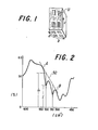
- FIG. 2 An example of the infrared absorption spectrum of a crystal is shown in Figure 2.
- the vertical axis represents transparent ratio (%) and the horizontal axis represents wave number (cm -1 ).
- the proportion of I-type crystal can be found by measuring the absorbance ratio at 510 cm -1 and 530 cm -1 , represented as D 510' D 530 respectively. Absorbance at 51 0 cm -1 corresponds to the absorption by I-type crystals and the absorbance at 530 cm -1 corresponds to the absorption by II-type crystals.
- Point A is plotted at a peak value around 530 cm -1
- point B is plotted at a peak value around 510 cm -1
- a base line 50 is drawn from A to B.
- Absorbances D 510 and D 530 are the differences between base line (I O ) and transparent rate (I) at 510 cm -1 and 530 cm -1 respectively. Using these absorbances, the ratio of I-type crystal in a crystal can be calculated by the formula:
- This ratio is desirably more than 50%, more preferably more than 65%, more preferably still more than 75%.
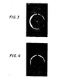
- the orientation of the crystals is judged by wide angle X-ray diffraction photography.
- a wide angle X-ray diffraction photograph is taken by setting the film cross section, which is cut perpendicular to the stretching direction, while placing its width direction vertically.
- the film is subjected to X-rays (CuKa rays) in a direction perpendicular to its cross section.
- the crystal orientation mode is judged by whether the diffraction images on the face (200) and face (110) of the I-type crystals form 6-dot images or 6-arcuate images or not.
- Films exhibiting 6-arcuate images, although somewhat indistinct as shown in Figure 3, are within the scope of films prepared in accordance with this invention. That is to say, if the axis b is oriented nearly vertically to the film surface, it is regarded as being substantially oriented vertically.
- the configuration in Figure 3 may be seen as a ring if not observed carefully.
- the intensities of the diffraction images situated at the top and bottom of the photograph, which can be recognised as arcuate images on the face (200), and of the images situated along four oblique directions, which can be recognised as the arcuate images on the face (110) appear greater than those in their vicinity.
- the diffraction intensities of the images at these locations are not greater than those at other locations. Consequently, the two cases can be distinguished form each other.
- Whether or not the dipoles are oriented substantially in the direction of the film thickness is judged by whether the images on the face (200) are formed as dot images or arcuate images at the top and bottom as shown in Figure 3. If the images of the face (200) are formed at the right and the left of the photograph, it shows that the dipoles are oriented in parallel with the film surfaces.
- the apparatus shown in Figure 5 comprises stretching means 2, 2' for pinching film 1 therebetween and stretching it in the direction of the arrow, and needle-like electrodes 3, 3' spaced 10 -2 m(1 cm) from the surfaces of the film 1 in a thermostat 4.
- the stretching means 2, 2' are threaded for engagement with the threads 6 formed on shaft 5 and are adapted to move horizontally on rotation of the shaft.
- needles are actually arranged side by side for each surface of the film 1 having 2 x 10 m (2 cm) width.
- a positive voltage is applied to the needle electrodes 3 and a negative voltage is applied to the needle electrodes 3'.
- a film 1 of 10 -4 m (100 ⁇ ) thickness made of vinylidene fluoride homopolymer or a film of 1.4 x 10 -4 m (140 u) thickness made of a copolymer consisting of 95% by weight of vinylidene fluoride and 5% by weight of vinyl fluoride was fixed to the stretching means 2, 2'.
- the stretching means were operated by rotation of the shaft 5 to stretch each film by a stretching factor of 4 at a predetermined temperature for 10 min while applying +6KV to the upper electrode 3 and -6KV to the lower electrode 3' to thereby produce corona discharging. Since films could not be stretched by afactor of 4 at 25°C and 30°C, they were stretched by a factor of 3.7 at these temperatures.
- the homopolymer and copolymer films were first stretched at 80°C by a factor of 4 then subjected to a corona discharge for 10 minutes by applying +6KV to the upper electrode 3 and -6KV to the lower electrode 3' at temperatures of 25°C, 30°C, 40°C, 50°C, 60°C, 70°C, 80°C, 100°C and 120°C using the apparatus as shown in Figure 5. Thereafter, the films were cooled to room temperature. The results are also shown in Table 1 (polyvinylidene fluoride homopolymer) and Table 2 (copolymer).
- the polyvinylidene fluoride homopolymer films obtained by the process of this invention have greater piezoelectric constants and pyroelectric coefficients and are more stable over a period of time as compared with those obtained by conducting polarization after separately stretching the films. The same results also occurred for the vinylidene fluoride copolymer films.
- the needle electrodes may be arranged in several rows.
- the film was stretched in two-directions, i.e. to the right and to the left in Figure 5, it is possible to stretch the film in other ways, for example by pulling it in one direction such as between two take-up rolls while a corona discharge is generated. Such an embodiment is shown below.
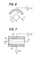
- Figure 6 shows another embodiment for practicing this invention.
- a film 11 of 6 x 10 -5 m (60 p) thickness made of vinylidene fluoride homopolymer runs from the left side of Figure 6 by way of a send roll (not shown) h i to a heating roll 12 at 1.66 x 10 -3 m/s (10 cm/min) then pulled from the heating roll 12 to the right by a take-up roll (not shown) at 6.66 x 10 m/s (40 cm/min) and made into a film 11' of 2.5 x 10 -5 m (25 ⁇ ) thickness on the right side of the heating roll 12.
- the heating roll 12 has 2 x 10 -1 m (20 mm) diameter. It is earthed and heated to a surface temperature of 110°C.
- the films prepared by this method had aluminum electrodes vapor-deposited on to both surfaces thereof and their piezoelectric constants d 31 were measured as in Example 1.
- the piezoelectric constant d 31 was 32 x 10 -12 C/N immediately after preparation and 28 x 10 -12 C/N one month afterwards.
- Figure 7 shows further apparatus for practicing this invention.
- a film 21 of 10 -4 m (100 ⁇ ) thickness made of vinylidene fluoride homopolymer runs from the left in Figure 7 by a send roll (not shown) to a temperature control bath 22 at 1.66 x 10 -3 m/s (10 cm/min) and then is stretched to the right of the control bath 22 at 6.66 x 10 -3 m/s (40 cm/min) by another roll (not shown) and made into a film 21' 3.3 x 10 -5 m (33u) thick.
- the temperature control bath 22 is maintained to 45°C and necking stretching was conducted in this bath.
- Needle electrode groups 23, 23' are provided 1 cm above and below the films 21 and 21'.
- a voltage of +6KV is applied to the needle electrodes 23 and of -6KV is applied to the needle electrodes 23' from high voltage DC power supplies 24, 24' during stretching.
- the films prepared in this way were vapor-deposited with aluminum electrodes on both surfaces thereof.
- Their piezoelectric constants d 31 were measured as in Example 1. The constant was 35 x 1 0 12 C/N immediately after preparation and 31 x 10 -12 C/N one month afterwards.
- the proportion of I-type crystal in the crystal system of the stretched films was 70% as measured by infrared absorption.
- the crystal orientation mode was as shown in Figure 3.
- films were treated in the same manner except that polarization was conducted after stretching.
- the piezoelectric constant d 31 of such comparative films was 27 x 10 -12 C/N just after their preparation and 19 x 10 -12 C/N after one month.
- the proportion of I-type crystal in the crystal system of the stretched films was 75% and the crystal orientation mode was as shown in Figure 4.
- the films prepared according to this invention are polarized under the application of an electric field, they can be used as they are as piezoelectric films or pyroelectric films. They may have high piezoelectric constants and pyroelectric coefficients as well as being stable and can be prepared as thin films. Accordingly, they can be used wherever conventional piezoelectric films or pyroelectric films find applications, for example as the dielectric material such as in capacitors. Furthermore, since their dipoles are oriented in specific directions, the films prepared according to this invention may possess excellent photoelectric properties, and, are industrially useful in a broad range of electrical materials.
- piezoelectric and pyroelectric films having a thickness below 50 u, preferably below 40 ⁇ more preferably below 30 ⁇ , and having a double-oriented structure in which dipoles are oriented substantially in the direction of the thickness of the film.
Abstract
Description
- This invention relates to piezolelectric and pyroelectric films prepared by stretching and polarizing a polymeric film.
- Polymeric materials such as polyvinylidene fluoride or polyvinyl fluoride are piezoelectric and pyroelectric when they are made into electrets, for exanple, by the application of a d.c. electric field under heating. In the process of preparing a piezoelectric and pyroelectric film from a polymeric film, the steps of stretching the film and applying a voltage across the film are necessary. These steps may be conducted either separately or simultaneously.
- The former technique of separately stretching a polymeric film before the application of a voltage across it has been employed widely. High polymeric films having high piezoelectricity aid pyroelectricity, can be obtained. However, the piezoelectric and pyroelectric effects thus obtained are unstable and reduce with time. On the other hand, piezoelectric and pyroelectric polymeric films obtained by the latter method of simultaneously stretching and applying a voltage do not provide high piezoelectricity and pyroelectricity, although they are stable.
- An example of the latter method is published in Japanese Patent Publication No. 4'5798/76 in which a high polymeric film is polarized while stretched in a pair of rolls across which a voltage is applied. It is difficult to obtain a high piezoelectric constant and pyroelectric coefficient in this process since only a restricted portion of the film is polarized, that is at the contact point with the rolls, and the polarizing time is not sufficient,
- A method of stretching a film while positioning plate electrodes close to both sides of it and applying a voltage between the electrodes is also known. Insufficient piezoelectric and pyroelectric properties are derived this way, however, since if the electrodes are kept in close contact with the film before stretching they can not be kept in this state during stretching.
- Polyvinylidene fluoride (PVDF) takes various crystalline forms including a-type, 0-type and y-type. PVDF films in the form of the β-type or the y-type are useful as dielectric materials. Their molecule chains have a planar zig-zag conformation and unit cell dipole moments exist. The β-type and the y-type crystalline forms are hereinafter referred to collectively as the I type although this is somewhat different from the usual meaning attributed to this term.
- I Type crystals can be obtained, for example, by stretching a heat molded sheet. The morphology depends on the method of stretching. According to the definition for crystallographic axes in Hasegawa et al, Polymer Journal, Vol. 3, No. 5, p. 600 - 610 (1972), the direction of the molecule chain is taken as axis c, the direction perpendicular to axis c and parallel with the dipoles is taken as axis b and the direction perpendicular both to axis c and axis b is taken as axis a. According to this definition, in a mono-axially stretched film axis c tends to be arranged in the direction of stretching when viewing the film surface, whilst axes a and b tend to be arranged at random looking at a cross section of the film perpendicular to the stretching direction. On the other hand, in a bi-axially oriented film axis c tends to be arranged at random when viewing the film surface, but axis b is aligned parallel to the film surface and axis a is aligned in a direction perpendicular to the film surface when viewing a cross section of the film.
- Since mono-axially and bi-axially stretched PVDF films have a dielectric constant of 10 to 13, which is 3 to 4 times as great as that of polyester films, they are utilized as capacitors in portable medical defibrillators. Their use as capacitors for nuclear fusion devices is under consideration. So-called double oriented PVDF films composed of I type crystals in which both axes c and b are oriented and, accordingly, axis a is also oriented have, however, become known only recently. In one such film, reported in DE-OS 29 30 370, the dipoles are oriented parallel with the film surface. In the Journal of Applied Physics, Vol. 50, p. 6091 - 6094, a film is disclosed in which the dipoles are oriented perpendicular to the film surfaces. The latter film is obtained by stretching and then rolling a film. However, in order to obtain a desired film thickness the film has to be rolled several times. Further, the thickness of the film obtained even after repeated rolling is at least about 60 p. In the case of a piezoelectric film in which dipoles are oriented perpendicular to the film surface, films should be as thin as possible since a thicker film is less likely to vibrate as compared with a thinner film of the same substance. In the case of a pyroelectric film, it is also desired to decrease the film thickness since heat capacitance is greater and sensitive conversion of temperature changes into electric changes is difficult as the film thickness increases.
- In an effort to overcome the problems associated with prior art methods of preparing piezoelectric and pyroelectric films, the present invention provides a process for preparing a piezoelectric pyroelectric film of a high polymer which process comprises stretching a polyvinylidene fluoride type film disposed between electrodes whilst causing a corona discharge between said electrodes to thereby polarize said film.
- Preferably, the tip of at least one of the electrodes between which the polymeric film is positioned when it is stretched is pointed. Such electrodes may be needle-like or saw teeth-like in shape. An electrode of such configuration may be provided on at least one side of the film to be stretched. The pointed electrodes are disposed so that corona discharge occurs at least where the film is stretched. A plurality of electrodes may be provided on one side or on both sides of the film. If corona discharging is conducted under heating, it is preferable to continue the discharge until the film has cooled to some extent after the stretching. The discharge can begin before stretching. The polymeric film is stretched transversely-to the electric field due to the corona discharge.
- In the process of this invention, satisfactory results can be obtained by setting the temperature during polarization and stretching preferably below 80°C, more preferably between room temperature (15°C) and 70°C, and more preferably between 30 and 60°C. Better results can be obtained if the temperature is towards the top end of these ranges if the stretching ratio and the stretching speed are great or is towards the lower end of these ranges if the stretching ratio and stretching speed are small.
- The polymeric films usable in this invention are polyvinylidene fluoride type films or sheets, for example of vinylidene fluoride homopolymer, a copolymer of vinylidene fluoride and at least one comonomer copolymerizable therewith, for example a halogenoalkene such as vinyl fluoride, tetrafluoroethylene or chlorotrifluoroethylene, the copolymer containing more than 50 mol% of vinylidene fluoride units in the main polymer chain, or a composition consisting predominantly of such a homopolymer and/or copolymer and also containing a compatible resin, for example poly(methyl methacrylate) or poly(methyl acrylate). Other materials may be included in the composition.
- Stretched or non-stretched polyvinylidene fluoride type films or sheets may be used. For example, double-oriented piezoelectric pyroelectric films in which dipoles are oriented substantially in the direction of the thickness can be provided by stretching a previously stretched film in a direction substantially perpendicular to the previous stretching direction, while corona discharging.
- The PVDF films obtained by the process of the invention can easily attain a thickness below 50)i and mainly consist of I-type crystals in which dipoles are oriented substantially in the direction of the thickness to form double orientation.
- The invention is further described, by way of example, referring to the accompanying drawings in which:
- Figure 1 is a schematic view showing the structure of a polyvinylidene fluoride film obtained by a process according to this invention;
- Figure 2 is an infrared absorption spectrum of polyvinylidene fluoride;
- Figure 3 is a wide angle X-ray diffraction photograph for a piezoelectric and pyroelectric film prepared according to this invention;
- Figure 4 is a wide angle X-ray diffraction photograph where axes a and b are oriented randomly;
- Figure 5 is a schematic view of one type of device which may be employed to carry out the process of this invention;
- Figure 6 is a schematic view of a further type of device which may be employed to carry out the process of this invention; and
- Figure 7 is a schematic view of a still further type of device which may be employed to carry out the process of this invention.
- As shown in Figure 1, PVDF film which is prepared by this invention is a film of double-orientation which consists essentially of I-type crystals. In Figure 1, a, b, c correspond to the directions of the axes a, b, and c, axis b being vertical to the film surface, and U denotes each crystallite.
- The proportion of I-type crystal in a given crystal can be determined by infrared absorption spectroscopy. The degree of the double orientation can be judged by using wide angle X-ray diffraction photography. These techniques are discussed below:
- An example of the infrared absorption spectrum of a crystal is shown in Figure 2. In this Figure, the vertical axis represents transparent ratio (%) and the horizontal axis represents wave number (cm-1). The proportion of I-type crystal can be found by measuring the absorbance ratio at 510 cm-1 and 530 cm-1, represented as D 510' D 530 respectively. Absorbance at 510 cm-1 corresponds to the absorption by I-type crystals and the absorbance at 530 cm-1 corresponds to the absorption by II-type crystals.
- Point A is plotted at a peak value around 530 cm-1, and point B is plotted at a peak value around 510 cm-1. A
base line 50 is drawn from A to B. Absorbances D 510 and D 530 are the differences between base line (IO) and transparent rate (I) at 510 cm-1 and 530 cm-1 respectively. Using these absorbances, the ratio of I-type crystal in a crystal can be calculated by the formula: - Ratio of I-type crystal in crystal (%)

- This ratio is desirably more than 50%, more preferably more than 65%, more preferably still more than 75%.
- The orientation of the crystals is judged by wide angle X-ray diffraction photography. A wide angle X-ray diffraction photograph is taken by setting the film cross section, which is cut perpendicular to the stretching direction, while placing its width direction vertically. The film is subjected to X-rays (CuKa rays) in a direction perpendicular to its cross section. The crystal orientation mode is judged by whether the diffraction images on the face (200) and face (110) of the I-type crystals form 6-dot images or 6-arcuate images or not.
- As the degree of the double orientation becomes more significant, the 6-dot images are observed more clearly as 6 points. As the degree of the double orientation diminishes the 6-dot images become blurred into 6-arcuate images as shown in Figure 3. Further, if the axes a and b are oriented at random in the film cross section, ring-like images on the same circle are observed as shown in Figure 4.
- Films exhibiting 6-arcuate images, although somewhat indistinct as shown in Figure 3, are within the scope of films prepared in accordance with this invention. That is to say, if the axis b is oriented nearly vertically to the film surface, it is regarded as being substantially oriented vertically. The configuration in Figure 3 may be seen as a ring if not observed carefully. However, the intensities of the diffraction images situated at the top and bottom of the photograph, which can be recognised as arcuate images on the face (200), and of the images situated along four oblique directions, which can be recognised as the arcuate images on the face (110), appear greater than those in their vicinity. On the other hand, in Figure 4 the diffraction intensities of the images at these locations are not greater than those at other locations. Consequently, the two cases can be distinguished form each other.
- Whether or not the dipoles are oriented substantially in the direction of the film thickness is judged by whether the images on the face (200) are formed as dot images or arcuate images at the top and bottom as shown in Figure 3. If the images of the face (200) are formed at the right and the left of the photograph, it shows that the dipoles are oriented in parallel with the film surfaces.
- The following Examples illustrate the invention:
- The apparatus shown in Figure 5 comprises stretching means 2, 2' for pinching film 1 therebetween and stretching it in the direction of the arrow, and needle-
like electrodes 3, 3' spaced 10-2m(1 cm) from the surfaces of the film 1 in athermostat 4. The stretching means 2, 2' are threaded for engagement with thethreads 6 formed on shaft 5 and are adapted to move horizontally on rotation of the shaft. - Although single needle-
like electrodes 3, 3' are illustrated in Figure 5, needles are actually arranged side by side for each surface of the film 1 having 2 x 10 m (2 cm) width. A positive voltage is applied to theneedle electrodes 3 and a negative voltage is applied to the needle electrodes 3'. - The method of producing piezoelectric and pyroelectric polyvinylidene fluoride films using this apparatus is described as follows:
- A film 1 of 10-4m (100 µ) thickness made of vinylidene fluoride homopolymer or a film of 1.4 x 10⁻⁴m (140 u) thickness made of a copolymer consisting of 95% by weight of vinylidene fluoride and 5% by weight of vinyl fluoride was fixed to the stretching means 2, 2'. The stretching means were operated by rotation of the shaft 5 to stretch each film by a stretching factor of 4 at a predetermined temperature for 10 min while applying +6KV to the
upper electrode 3 and -6KV to the lower electrode 3' to thereby produce corona discharging. Since films could not be stretched by afactor of 4 at 25°C and 30°C, they were stretched by a factor of 3.7 at these temperatures. - When the film had cooled to room temperature after the stretching, the corona discharging was stopped. The piezoelectric constant d31 for 10 Hz vibration at room temperature and the pyroelectric coefficient dPs/dT at 23°C were measured for the piezoelectric and pyroelectric films thus formed onto which silver electrodes had been vapor-deposited. The results are shown in Table 1 (polyvinylidene fluoride homopolymer) and Table 2 (copolymer).
- As a comparison; the homopolymer and copolymer films were first stretched at 80°C by a factor of 4 then subjected to a corona discharge for 10 minutes by applying +6KV to the
upper electrode 3 and -6KV to the lower electrode 3' at temperatures of 25°C, 30°C, 40°C, 50°C, 60°C, 70°C, 80°C, 100°C and 120°C using the apparatus as shown in Figure 5. Thereafter, the films were cooled to room temperature. The results are also shown in Table 1 (polyvinylidene fluoride homopolymer) and Table 2 (copolymer).

- As can be seen from the Tables 1 and 2, the polyvinylidene fluoride homopolymer films obtained by the process of this invention have greater piezoelectric constants and pyroelectric coefficients and are more stable over a period of time as compared with those obtained by conducting polarization after separately stretching the films. The same results also occurred for the vinylidene fluoride copolymer films.
- It will be apparent that while six needles are arranged in one row on one side in the foregoing embodiment, the needle electrodes may be arranged in several rows. In addition, while the film was stretched in two-directions, i.e. to the right and to the left in Figure 5, it is possible to stretch the film in other ways, for example by pulling it in one direction such as between two take-up rolls while a corona discharge is generated. Such an embodiment is shown below.
- Figure 6 shows another embodiment for practicing this invention. A film 11 of 6 x 10⁻⁵m (60 p) thickness made of vinylidene fluoride homopolymer runs from the left side of Figure 6 by way of a send roll (not shown) h i to a
heating roll 12 at 1.66 x 10⁻³m/s (10 cm/min) then pulled from theheating roll 12 to the right by a take-up roll (not shown) at 6.66 x 10 m/s (40 cm/min) and made into a film 11' of 2.5 x 10⁻⁵m (25 µ) thickness on the right side of theheating roll 12. Theheating roll 12 has 2 x 10⁻¹m (20 mm) diameter. It is earthed and heated to a surface temperature of 110°C.Five needle electrodes 13 with appropriate needle pitch are disposed pointing toward the centre of theheating roll 12. These electrodes-are spaced 8 x 10 2m (8 mm) from the surface of theheating roll 12. An 8 KV voltage is applied between the needle electrodes and the roll surface by means of a high voltageDC power supply 14. The films prepared by this method had aluminum electrodes vapor-deposited on to both surfaces thereof and their piezoelectric constants d31 were measured as in Example 1. The piezoelectric constant d31 was 32 x 10-12C/N immediately after preparation and 28 x 10-12C/N one month afterwards. - Figure 7 shows further apparatus for practicing this invention. A
film 21 of 10-4m (100 µ) thickness made of vinylidene fluoride homopolymer runs from the left in Figure 7 by a send roll (not shown) to atemperature control bath 22 at 1.66 x 10 -3m/s (10 cm/min) and then is stretched to the right of thecontrol bath 22 at 6.66 x 10⁻³m/s (40 cm/min) by another roll (not shown) and made into a film 21' 3.3 x 10⁻⁵m (33u) thick. Thetemperature control bath 22 is maintained to 45°C and necking stretching was conducted in this bath.Needle electrode groups 23, 23' are provided 1 cm above and below thefilms 21 and 21'. A voltage of +6KV is applied to theneedle electrodes 23 and of -6KV is applied to the needle electrodes 23' from high voltage DC power supplies 24, 24' during stretching. The films prepared in this way were vapor-deposited with aluminum electrodes on both surfaces thereof. Their piezoelectric constants d31 were measured as in Example 1. The constant was 35 x 10 12 C/N immediately after preparation and 31 x 10-12C/N one month afterwards. The proportion of I-type crystal in the crystal system of the stretched films was 70% as measured by infrared absorption. The crystal orientation mode was as shown in Figure 3. For comparison, films were treated in the same manner except that polarization was conducted after stretching. The piezoelectric constant d31 of such comparative films was 27 x 10-12 C/N just after their preparation and 19 x 10 -12 C/N after one month. The proportion of I-type crystal in the crystal system of the stretched films was 75% and the crystal orientation mode was as shown in Figure 4. - Since the films prepared according to this invention are polarized under the application of an electric field, they can be used as they are as piezoelectric films or pyroelectric films. They may have high piezoelectric constants and pyroelectric coefficients as well as being stable and can be prepared as thin films. Accordingly, they can be used wherever conventional piezoelectric films or pyroelectric films find applications, for example as the dielectric material such as in capacitors. Furthermore, since their dipoles are oriented in specific directions, the films prepared according to this invention may possess excellent photoelectric properties, and, are industrially useful in a broad range of electrical materials.
- By adopting the process of the present invention it is possible to obtain piezoelectric and pyroelectric films having a thickness below 50 u, preferably below 40 µ more preferably below 30 µ, and having a double-oriented structure in which dipoles are oriented substantially in the direction of the thickness of the film.
Claims (10)
Applications Claiming Priority (2)
| Application Number | Priority Date | Filing Date | Title |
|---|---|---|---|
| JP5194079A JPS55157801A (en) | 1979-04-26 | 1979-04-26 | Process for producing piezooelectric current collecting high molecular film |
| JP51940/79 | 1979-04-26 |
Publications (2)
| Publication Number | Publication Date |
|---|---|
| EP0018802A1 true EP0018802A1 (en) | 1980-11-12 |
| EP0018802B1 EP0018802B1 (en) | 1984-05-23 |
Family
ID=12900855
Family Applications (1)
| Application Number | Title | Priority Date | Filing Date |
|---|---|---|---|
| EP80301372A Expired EP0018802B1 (en) | 1979-04-26 | 1980-04-25 | Process for preparing a piezoelectric pyroelectric film, and capacitors, piezoelectric and pyroelectric devices incorporating the film |
Country Status (4)
| Country | Link |
|---|---|
| US (1) | US4308370A (en) |
| EP (1) | EP0018802B1 (en) |
| JP (1) | JPS55157801A (en) |
| DE (1) | DE3067927D1 (en) |
Cited By (6)
| Publication number | Priority date | Publication date | Assignee | Title |
|---|---|---|---|---|
| EP0089770A1 (en) * | 1982-03-18 | 1983-09-28 | British Telecommunications | Piezoelectric and pyroelectric film |
| EP0131231A2 (en) * | 1983-07-07 | 1985-01-16 | Unitika Ltd. | Process for producing a piezo- and pyro-electric film |
| EP0141674A2 (en) * | 1983-11-08 | 1985-05-15 | Celanese Corporation | Electret process and products |
| US5087679A (en) * | 1989-04-07 | 1992-02-11 | Daikin Industries Ltd. | Polymeric dielectrics |
| US8698361B2 (en) | 2009-11-05 | 2014-04-15 | Siemens Aktiengesellschaft | Arrangement for cooling of an electrical machine |
| WO2014161920A1 (en) * | 2013-04-03 | 2014-10-09 | Swerea Ivf Ab | Method of producing a piezoelectric and pyroelectric fiber |
Families Citing this family (30)
| Publication number | Priority date | Publication date | Assignee | Title |
|---|---|---|---|---|
| EP0047740A1 (en) * | 1979-11-30 | 1982-03-24 | National Research Development Corporation | Vinylidene fluoride polymers |
| US4510300A (en) * | 1982-04-08 | 1985-04-09 | E. I. Du Pont De Nemours And Company | Perfluorocarbon copolymer films |
| DE3219538A1 (en) * | 1982-05-25 | 1983-12-01 | Softal Electronic GmbH, 2000 Hamburg | DEVICE FOR THE ELECTRICAL PRE-TREATMENT OF NON-CONDUCTIVE FILMS |
| US4510301A (en) * | 1982-06-01 | 1985-04-09 | E. I. Du Pont De Nemours And Company | Fluorocarbon copolymer films |
| DE3406125A1 (en) * | 1984-01-31 | 1985-08-01 | Norddeutsche Seekabelwerke Ag, 2890 Nordenham | Process and device for producing piezoelectric and/or pyroelectric polyvinylidene fluoride films |
| US4668449A (en) * | 1984-09-11 | 1987-05-26 | Raychem Corporation | Articles comprising stabilized piezoelectric vinylidene fluoride polymers |
| US4565615A (en) * | 1984-11-01 | 1986-01-21 | Pennwalt Corporation | Glow discharge stabilization of piezoelectric polymer film |
| US5192470A (en) * | 1986-02-27 | 1993-03-09 | Raytheon Company | Method of stretching and polarizing polymer materials |
| US4863648A (en) * | 1986-07-03 | 1989-09-05 | Rutgers, The State University Of New Jersey | Process for making polarized material |
| US4830795A (en) * | 1986-07-03 | 1989-05-16 | Rutgers, The State University Of New Jersey | Process for making polarized material |
| US5271876A (en) * | 1986-12-02 | 1993-12-21 | Solomat Partners, L.P. | Process for analyzing, monitoring and/or controlling the internal structure of non-conductive, moldable material by inducing an electrical effect therein before it is molded |
| US5326393A (en) * | 1986-12-02 | 1994-07-05 | Solomat Partners, L.P. | Process for determining the actual temperature of a moldable material contained within a mold or passed through a die |
| US4778867A (en) * | 1987-07-21 | 1988-10-18 | Seymour Pries | Ferroelectric copolymers of vinylidene fluoride and trifluoroethylene with increased Curie temperature and their methods of production |
| JPH0253932A (en) * | 1988-08-11 | 1990-02-22 | Toray Ind Inc | Production of drawn molded article of plastics |
| CA2032015A1 (en) * | 1990-12-11 | 1992-06-12 | Martin Perlman | Method to double the piezo - and pyroelectric constants of polyvinylinde fluoride (pvdf) films |
| US5310511A (en) * | 1992-03-24 | 1994-05-10 | Eastman Kodak Company | Method and apparatus for poling a planar polarizable body |
| FR2700219B1 (en) * | 1993-01-06 | 1995-02-17 | Saint Louis Inst | Method for electrically depolarizing a ferroelectric material and its application for obtaining ferroelectric material with reinforced rigidity. |
| US5494617A (en) * | 1994-05-16 | 1996-02-27 | The United States Of America As Represented By The Secretary Of The Navy | Method of inducing piezoelectric properties in polymers |
| US6001299A (en) * | 1995-02-21 | 1999-12-14 | Japan Vilene Company, Ltd. | Process and apparatus for manufacturing an electret article |
| US6979479B2 (en) * | 2003-03-14 | 2005-12-27 | Lockheed Martin Corporation | Flexible material for lighter-than-air vehicles |
| WO2004086419A1 (en) * | 2003-03-26 | 2004-10-07 | Daikin Industries Ltd. | Method for forming ferroelectric thin film |
| JP3867709B2 (en) * | 2003-03-26 | 2007-01-10 | ダイキン工業株式会社 | Thin film formation method |
| PT103318B (en) * | 2005-07-19 | 2009-01-22 | Univ Do Minho | NON-POROUS FILMS IN THE BETA POLY PHASE (VINYLIDENE FLUORIDE) (PVDF) AND METHOD FOR THEIR PROCESSING |
| JP4964888B2 (en) * | 2005-09-21 | 2012-07-04 | ロッキード・マーチン・コーポレーション | Lighter than air |
| US20070281570A1 (en) * | 2006-05-30 | 2007-12-06 | Liggett Paul E | Reduced weight flexible laminate material for lighter-than-air vehicles |
| US7878453B2 (en) * | 2008-01-28 | 2011-02-01 | Lockheed Martin Corporation | Piezoelectric and pyroelectric power-generating laminate for an airship envelope |
| US20090263671A1 (en) * | 2008-04-21 | 2009-10-22 | Kui Yao | Ferroelectric Poly (Vinylidene Fluoride) Film on a Substrate and Method for its Formation |
| RU2635804C1 (en) * | 2016-08-04 | 2017-11-16 | Федеральное государственное бюджетное учреждение науки Институт высокомолекулярных соединений Российской академии наук | Method for producing polymeric piezo films with layers of electro-conducting polymers |
| JP6995669B2 (en) * | 2018-03-05 | 2022-01-14 | 株式会社クレハ | Piezoelectric film, method of manufacturing piezoelectric film, and piezoelectric device |
| CN114953296B (en) * | 2022-05-26 | 2023-08-29 | 业成科技(成都)有限公司 | Manufacturing method of polycrystalline polyvinylidene fluoride film and wearable device |
Citations (3)
| Publication number | Priority date | Publication date | Assignee | Title |
|---|---|---|---|---|
| FR2265805A1 (en) * | 1974-03-25 | 1975-10-24 | Verto Nv | |
| FR2275033A1 (en) * | 1974-06-17 | 1976-01-09 | Minnesota Mining & Mfg | POLARIZATION MACHINE AND METHOD |
| GB2020483A (en) * | 1978-03-21 | 1979-11-14 | Post Office | Improvements in or relating to piezoelectric materials and to apparatus and methods for producing such material |
Family Cites Families (4)
| Publication number | Priority date | Publication date | Assignee | Title |
|---|---|---|---|---|
| US2935418A (en) * | 1953-06-03 | 1960-05-03 | Olin Mathieson | Method for treating preformed polyethylene with an electrical glow discharge |
| JPS497959B1 (en) * | 1969-07-17 | 1974-02-23 | ||
| US3931446A (en) * | 1970-09-26 | 1976-01-06 | Kureha Kagaku Kogyo Kabushiki Kaisha | Process for producing polymeric piezoelectric elements and the article formed thereby |
| US4095020A (en) * | 1977-02-25 | 1978-06-13 | Xerox Corporation | Process for controlled phase transformation of alpha phase of poly(vinylidene fluoride) to the gamma phase |
-
1979
- 1979-04-26 JP JP5194079A patent/JPS55157801A/en active Granted
-
1980
- 1980-04-21 US US06/142,265 patent/US4308370A/en not_active Expired - Lifetime
- 1980-04-25 EP EP80301372A patent/EP0018802B1/en not_active Expired
- 1980-04-25 DE DE8080301372T patent/DE3067927D1/en not_active Expired
Patent Citations (3)
| Publication number | Priority date | Publication date | Assignee | Title |
|---|---|---|---|---|
| FR2265805A1 (en) * | 1974-03-25 | 1975-10-24 | Verto Nv | |
| FR2275033A1 (en) * | 1974-06-17 | 1976-01-09 | Minnesota Mining & Mfg | POLARIZATION MACHINE AND METHOD |
| GB2020483A (en) * | 1978-03-21 | 1979-11-14 | Post Office | Improvements in or relating to piezoelectric materials and to apparatus and methods for producing such material |
Non-Patent Citations (1)
| Title |
|---|
| JOURNAL OF APPLIED PHYSICS, Vol. 41, No. 6, May 1970, pages 2365-2375 New York, U.S.A. R.A. CRESWELL: "Thermal Currents from Corona Charged Mylar". * Pages 2368-2369 * * |
Cited By (9)
| Publication number | Priority date | Publication date | Assignee | Title |
|---|---|---|---|---|
| EP0089770A1 (en) * | 1982-03-18 | 1983-09-28 | British Telecommunications | Piezoelectric and pyroelectric film |
| US4557880A (en) * | 1982-03-18 | 1985-12-10 | British Telecommunications | Piezoelectric and pyroelectric film |
| EP0131231A2 (en) * | 1983-07-07 | 1985-01-16 | Unitika Ltd. | Process for producing a piezo- and pyro-electric film |
| EP0131231A3 (en) * | 1983-07-07 | 1985-09-18 | Unitika Ltd. | Process for producing a piezo- and pyro-electric film |
| EP0141674A2 (en) * | 1983-11-08 | 1985-05-15 | Celanese Corporation | Electret process and products |
| EP0141674A3 (en) * | 1983-11-08 | 1985-09-18 | Celanese Corporation | Electret process and products |
| US5087679A (en) * | 1989-04-07 | 1992-02-11 | Daikin Industries Ltd. | Polymeric dielectrics |
| US8698361B2 (en) | 2009-11-05 | 2014-04-15 | Siemens Aktiengesellschaft | Arrangement for cooling of an electrical machine |
| WO2014161920A1 (en) * | 2013-04-03 | 2014-10-09 | Swerea Ivf Ab | Method of producing a piezoelectric and pyroelectric fiber |
Also Published As
| Publication number | Publication date |
|---|---|
| DE3067927D1 (en) | 1984-07-05 |
| JPS6217801B2 (en) | 1987-04-20 |
| JPS55157801A (en) | 1980-12-08 |
| EP0018802B1 (en) | 1984-05-23 |
| US4308370A (en) | 1981-12-29 |
Similar Documents
| Publication | Publication Date | Title |
|---|---|---|
| EP0018802B1 (en) | Process for preparing a piezoelectric pyroelectric film, and capacitors, piezoelectric and pyroelectric devices incorporating the film | |
| US4668449A (en) | Articles comprising stabilized piezoelectric vinylidene fluoride polymers | |
| US4241128A (en) | Production of piezoelectric PVDF films | |
| US5356500A (en) | Piezoelectric laminate films and processes for their manufacture | |
| DE2235500C3 (en) | Process for the production of a film from polyvinylidene fluoride | |
| US4427609A (en) | Process for producing piezoelectric polymer films | |
| DE2930370C2 (en) | Process for making a doubly oriented film | |
| US4327153A (en) | Composite piezoelectric material in the form of a film and a method of fabrication of said material | |
| US5254296A (en) | Method to double the piezo-and pyroelectric of polyvinylidine fluoride (PVDF) films | |
| CA1333380C (en) | Process for making polarized material and polarized products | |
| US4390674A (en) | Uniaxially drawn vinylidene fluoride polymers | |
| US4830795A (en) | Process for making polarized material | |
| JP2782528B2 (en) | Method of forming organic piezoelectric pyroelectric film | |
| CA1204077A (en) | Reverse field stabilization of polarized polymer films | |
| US4591465A (en) | Method of producing polymeric electret element | |
| EP0050332B1 (en) | Corona discharge poling process | |
| JPS6133279B2 (en) | ||
| DE2147892B2 (en) | PROCESS FOR THE PRODUCTION OF PIEZOELECTRIC POLYVINYLIDEN FLUORIDE FILMS | |
| US4711808A (en) | Beta phase PVF2 film formed by casting it onto a specially prepared insulating support | |
| EP0174838A2 (en) | Stabilized piezoelectric vinylidene fluoride polymers | |
| Bloomfield | Production of ferroelectric oriented PVDF films | |
| EP0118757A2 (en) | Polymeric ferro-electric material | |
| US6495642B2 (en) | Process for preparing electrostrictive polymers and resulting polymers and articles | |
| Newman et al. | A new class of ferroelectric polymers, the odd-numbered nylons | |
| Bharti et al. | Quantitative analysis of piezoelectricity in simultaneously stretched and corona poled polyvinyl chloride films |
Legal Events
| Date | Code | Title | Description |
|---|---|---|---|
| PUAI | Public reference made under article 153(3) epc to a published international application that has entered the european phase |
Free format text: ORIGINAL CODE: 0009012 |
|
| AK | Designated contracting states |
Designated state(s): DE FR GB NL |
|
| 17P | Request for examination filed |
Effective date: 19810418 |
|
| GRAA | (expected) grant |
Free format text: ORIGINAL CODE: 0009210 |
|
| AK | Designated contracting states |
Designated state(s): DE FR GB NL |
|
| REF | Corresponds to: |
Ref document number: 3067927 Country of ref document: DE Date of ref document: 19840705 |
|
| ET | Fr: translation filed | ||
| RIN2 | Information on inventor provided after grant (corrected) |
Free format text: FUKADA, EIICHI * FURUKAWA, TAKEO * DATE, MUNEHIRO * TAKAMATSU, TOSHIAKI * NAKAMURA, KEN'ICHI |
|
| PLBE | No opposition filed within time limit |
Free format text: ORIGINAL CODE: 0009261 |
|
| STAA | Information on the status of an ep patent application or granted ep patent |
Free format text: STATUS: NO OPPOSITION FILED WITHIN TIME LIMIT |
|
| 26N | No opposition filed | ||
| PGFP | Annual fee paid to national office [announced via postgrant information from national office to epo] |
Ref country code: GB Payment date: 19910415 Year of fee payment: 12 |
|
| PGFP | Annual fee paid to national office [announced via postgrant information from national office to epo] |
Ref country code: FR Payment date: 19910426 Year of fee payment: 12 |
|
| PGFP | Annual fee paid to national office [announced via postgrant information from national office to epo] |
Ref country code: NL Payment date: 19910430 Year of fee payment: 12 |
|
| PGFP | Annual fee paid to national office [announced via postgrant information from national office to epo] |
Ref country code: DE Payment date: 19910531 Year of fee payment: 12 |
|
| PG25 | Lapsed in a contracting state [announced via postgrant information from national office to epo] |
Ref country code: GB Effective date: 19920425 |
|
| PG25 | Lapsed in a contracting state [announced via postgrant information from national office to epo] |
Ref country code: NL Effective date: 19921101 |
|
| NLV4 | Nl: lapsed or anulled due to non-payment of the annual fee | ||
| GBPC | Gb: european patent ceased through non-payment of renewal fee | ||
| PG25 | Lapsed in a contracting state [announced via postgrant information from national office to epo] |
Ref country code: FR Effective date: 19921230 |
|
| PG25 | Lapsed in a contracting state [announced via postgrant information from national office to epo] |
Ref country code: DE Effective date: 19930101 |
|
| REG | Reference to a national code |
Ref country code: FR Ref legal event code: ST |