EP0018770B1 - System protection valve - Google Patents
System protection valve Download PDFInfo
- Publication number
- EP0018770B1 EP0018770B1 EP19800301308 EP80301308A EP0018770B1 EP 0018770 B1 EP0018770 B1 EP 0018770B1 EP 19800301308 EP19800301308 EP 19800301308 EP 80301308 A EP80301308 A EP 80301308A EP 0018770 B1 EP0018770 B1 EP 0018770B1
- Authority
- EP
- European Patent Office
- Prior art keywords
- valve
- bleed
- plunger
- return valve
- recess
- Prior art date
- Legal status (The legal status is an assumption and is not a legal conclusion. Google has not performed a legal analysis and makes no representation as to the accuracy of the status listed.)
- Expired
Links
- 239000012530 fluid Substances 0.000 claims description 16
- 238000010586 diagram Methods 0.000 description 1
- 238000004519 manufacturing process Methods 0.000 description 1
- 230000000717 retained effect Effects 0.000 description 1
Images

Classifications
-
- B—PERFORMING OPERATIONS; TRANSPORTING
- B60—VEHICLES IN GENERAL
- B60T—VEHICLE BRAKE CONTROL SYSTEMS OR PARTS THEREOF; BRAKE CONTROL SYSTEMS OR PARTS THEREOF, IN GENERAL; ARRANGEMENT OF BRAKING ELEMENTS ON VEHICLES IN GENERAL; PORTABLE DEVICES FOR PREVENTING UNWANTED MOVEMENT OF VEHICLES; VEHICLE MODIFICATIONS TO FACILITATE COOLING OF BRAKES
- B60T11/00—Transmitting braking action from initiating means to ultimate brake actuator without power assistance or drive or where such assistance or drive is irrelevant
- B60T11/10—Transmitting braking action from initiating means to ultimate brake actuator without power assistance or drive or where such assistance or drive is irrelevant transmitting by fluid means, e.g. hydraulic
- B60T11/28—Valves specially adapted therefor
- B60T11/32—Automatic cut-off valves for defective pipes
- B60T11/326—Automatic cut-off valves for defective pipes in pneumatic systems
Definitions
- This invention relates to protection valves for fluid operated systems, for example, the service brakes, spring operated brakes and auxiliary systems of a vehicle.
- valves have to distribute fluid normally compressed air, to the system in a required sequence, to protect each system against loss of pressure in other systems and to enable all sound systems to be charged to a predetermined minimum operating pressure following system failure due to air leakage.
- the unit also enables the service systems to augment the supplementary systems.
- a protection valve in general, includes a housing containing two or more valve elements each of which opens against a bias to admit fluid under pressure to an associated fluid operated system and comprises a plunger biased toward a position wherein it closes off an outlet port for connection to the associated system and carrying an inlet non-return valve which is movable relative to the plunger, to uncover a bleed by-pass in communication with the said port.
- a valve is described in FR-A-2.316.106.
- the non return valves isolate the respective systems in the event of excessive reduction in pressure due to, for example, failure of the air supply system.
- the plunger reseats thus isolating the failed system.
- the remaining systems can be charged but only to the opening pressure of the element in the failed system. This pressure normally being set at a level sufficient to provide secondary or residual braking.
- DE-A-2.233.144 discloses a system protection valve according to the precharacterising part of claim 1 in which each valve element comprises a bleed hole through the inlet non-return valve leading via a bleed non-return valve to a bleed chamber which is permanently in communication with the outlet port for connection to the associated fluid operated system.
- one or more additional plunger type valve elements each associated with a supplementary system are connected (on parallel) to a flowpath linking the outlet ports associated with the service systems, the flow into the said flow-path at each junction being through a supplementary non-return valve (DE-B-2.525.146, fig. 2).
- Excessive air leakage in one of the supplementary systems causes air pressure in the service systems to fall to the closing pressure of the element in the failed system, the air in the remaining supplementary system(s) being retained by the non-return valve in the plunger.
- the elements in the supplementary systems are set out so that their opening pressures are sufficient to enable the service systems to provide secondary or residual braking in the event of supplementary system failure due to air leakage.
- valve elements associated with the supplementary systems could not, however, be made identical with the service system elements since the bleed hole is active at zero .pressure and above, so that in the event of a supplementary system failure, the service reservoirs feeding the supplementary system would also fail.
- a protection valve for fluid operated systems having two or more valve elements each of which opens against a bias to admit fluid under pressure to an associated fluid operated system and comprising a plunger controlling communication between an inlet port for fluid under pressure and an outlet port for connection to the associated system, and carrying an inlet non-return valve relatively movable to the plunger and has therethrough a bleed hole leading via a bleed chamber to the outlet port and incorporating a bleed non-return valve the plunger being biased toward a position wherein the inlet non-return valve closes-off the inlet port, characterised in that the bleed chamber is defined between the inlet non-return valve and the plunger which are relatively movable to open and close the bleed chamber and the effective areas on which pressure fluid acts are such that related movement of the plunger and the inlet non-return valve occurs to close the bleed chamber so cutting off communication between the bleed chamber and the outlet port, below the closing pressure of the valve element. Because the bleed non-return valve is only active between valve opening and closing
- valve elements can be identical, thus facilitating manufacture, even for multiple systems in which service systems are charged preferentially.
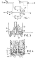
- Figure 1 shows a system protection valve 10 connected in a pneumatic vehicle braking circuit having a service braking systems 12, spring parking brake system 14 and auxiliaries 16. Compressed air is delivered to the inlet 1 of the system protection valve 10 from a reservoir 18 connected to a compressor (not shown) and is distributed to the service system 12 via service reservoirs 20 connected to outlet ports 21 and 22. The spring parking brakes and auxiliary systems are connected to supplementary outlet ports 23 and 24 of the system protection valve 10.
- valve 10 has four identical valve elements W, X, Y, Z of which elements W and X are associated with the service systems and elements Y and Z are associated with the supplementary systems 14 and 16, communicate with a flow path 26 interconnecting the outlet ports 21 and 22 via spring loaded non-return valves 28 and 30. Hence, the service systems are charged preferentially.
- Each of the valves W, X, Y, and Z have a plunger 40 which is sealed by an 0-ring 42 and loaded by a pre-set spring determining the opening pressure of the valve element.
- the plunger 40 carries an inlet non-return valve 44 having a boss 45 which is a clearance fit in a cylindrical recess 46 of the plunger 40, and seating on a circular lip or rim 48 around the face of the plunger.
- a smaller diameter rim or lip 50 on the opposite face of the non-return valve 44 co-operates with a fixed seat on the valve housing to close off communication with the inlet port 1 in the case of valve elements W and X or the flowpaths 26 in the case of supplementary valve elements Y and Z.
- the valve 44 has a bleed hole 52 normally closed by a spring-loaded valve 54 which seats on the face of the boss 45 within the recess 46 to close off communication via the clearance 56 between the boss 45 and the recess 46 (represented in figure 3 by a flowpath shown dotted) with a bleed chamber 47 defined between the end face of the plunger 40 and the inlet non-return valve 44 by lip or rim 48.
- air from the compressor or supply reservoir 18 is directed to valve elements W and X pressure in the bleed chamber 47 thus building-up through the bleed holes 52 to act on the larger seat diameter defined by the lip or rim 48.
- the plunger 40 lifts to permit air flowing through the bleed hole 52 to pass to the service reservoirs via ports 21 and 22.
- the inlet non-return valve 44 opens when the pressure of air increases to the point at which the pressure acting on the seat defined by the smaller lip or rim equals the opposing spring load.
- This pressure is the valve opening pressure. Once the valve is open this pressure acts on the 0-ring diameter (42) which is larger than the diameter of lip 50 so providing a further boost to valve opening. In this state, the valve 44 acts as a non-return valve in the direction of flow. After opening of the service valve elements W and X, air passes through the supplementary non-return valves 28 and 30 to valve elements Y and Z thus charging the supplementary systems. When charging ceases, the non-return valves 44, 28 and 30 re-seat but the plunger 40 remain unseated by virtue of back pressure in the associated systems.
- valve elements close at a pressure equal to the spring load divided by the area of 0-ring 42 internal diameter. This is referred to as the closing pressure.
- the non-return valve 44 has an off-set bleed hole 52 communicating with an annular recess 60 surrounding the valve stem 70 on one side of the non-return valve 44.
- This recess is normally covered by a spring loaded bleed non-return valve 54 housed in a recess 62 in the face of the plunger 40.
- the bleed non-return valve comprises a flexible disc 66 of rubber or the the like, which is pressed into its closed position ( Figure 4) by a spring loaded domed element 68 surrounding the stem 70 of the non-return valve and carried in a stepped recess 72 in the plunger concentric with the recess 62.
- the modified valve element of Figure 4 is identical with the valve element of Figure 3.
Landscapes
- Engineering & Computer Science (AREA)
- Transportation (AREA)
- Mechanical Engineering (AREA)
- Valves And Accessory Devices For Braking Systems (AREA)
Description
- This invention relates to protection valves for fluid operated systems, for example, the service brakes, spring operated brakes and auxiliary systems of a vehicle.
- Such valves have to distribute fluid normally compressed air, to the system in a required sequence, to protect each system against loss of pressure in other systems and to enable all sound systems to be charged to a predetermined minimum operating pressure following system failure due to air leakage. The unit also enables the service systems to augment the supplementary systems.
- In general, a protection valve includes a housing containing two or more valve elements each of which opens against a bias to admit fluid under pressure to an associated fluid operated system and comprises a plunger biased toward a position wherein it closes off an outlet port for connection to the associated system and carrying an inlet non-return valve which is movable relative to the plunger, to uncover a bleed by-pass in communication with the said port. Such a valve is described in FR-A-2.316.106. The non return valves isolate the respective systems in the event of excessive reduction in pressure due to, for example, failure of the air supply system. In the event of excessive loss of air pressure in one of the service systems, the plunger reseats thus isolating the failed system. The remaining systems can be charged but only to the opening pressure of the element in the failed system. This pressure normally being set at a level sufficient to provide secondary or residual braking.
- DE-A-2.233.144 discloses a system protection valve according to the precharacterising part of
claim 1 in which each valve element comprises a bleed hole through the inlet non-return valve leading via a bleed non-return valve to a bleed chamber which is permanently in communication with the outlet port for connection to the associated fluid operated system. - In multiple systems, it is often desirable to maintain preferential charging to the main service braking system and, to this end, one or more additional plunger type valve elements each associated with a supplementary system are connected (on parallel) to a flowpath linking the outlet ports associated with the service systems, the flow into the said flow-path at each junction being through a supplementary non-return valve (DE-B-2.525.146, fig. 2).
- Excessive air leakage in one of the supplementary systems causes air pressure in the service systems to fall to the closing pressure of the element in the failed system, the air in the remaining supplementary system(s) being retained by the non-return valve in the plunger. The elements in the supplementary systems are set out so that their opening pressures are sufficient to enable the service systems to provide secondary or residual braking in the event of supplementary system failure due to air leakage.
- The valve elements associated with the supplementary systems could not, however, be made identical with the service system elements since the bleed hole is active at zero .pressure and above, so that in the event of a supplementary system failure, the service reservoirs feeding the supplementary system would also fail.
- A protection valve for fluid operated systems according to this invention, having two or more valve elements each of which opens against a bias to admit fluid under pressure to an associated fluid operated system and comprising a plunger controlling communication between an inlet port for fluid under pressure and an outlet port for connection to the associated system, and carrying an inlet non-return valve relatively movable to the plunger and has therethrough a bleed hole leading via a bleed chamber to the outlet port and incorporating a bleed non-return valve the plunger being biased toward a position wherein the inlet non-return valve closes-off the inlet port, characterised in that the bleed chamber is defined between the inlet non-return valve and the plunger which are relatively movable to open and close the bleed chamber and the effective areas on which pressure fluid acts are such that related movement of the plunger and the inlet non-return valve occurs to close the bleed chamber so cutting off communication between the bleed chamber and the outlet port, below the closing pressure of the valve element. Because the bleed non-return valve is only active between valve opening and closing pressure, all sound systems can be completely protected against failure in any other system below valve closing pressure.
- Another advantage of a protection valve according to this invention is that the valve elements can be identical, thus facilitating manufacture, even for multiple systems in which service systems are charged preferentially.
- Other features of this invention are referred to in the appendant claims and in the following description of a preferred embodiment of the invention with reference to the accompanying drawings of which:
- Figure 1 is a diagram of a typical pneumatic vehicle braking circuit in which compressed air is distributed to the various systems via a system protection valve according to this invention.
- Figure 2 is a part cross-section of the system protection valve used in the circuit of Figure 1 having four identical valve elements, and
- Figure 3 is an enlarged diagrammatic view of one of the said valve elements and
- Figure 4 is an enlarged view similar to Figure 3 but of a modified valve element.
- Figure 1 shows a
system protection valve 10 connected in a pneumatic vehicle braking circuit having aservice braking systems 12, spring parking brake system 14 andauxiliaries 16. Compressed air is delivered to theinlet 1 of thesystem protection valve 10 from areservoir 18 connected to a compressor (not shown) and is distributed to theservice system 12 viaservice reservoirs 20 connected tooutlet ports supplementary outlet ports system protection valve 10. - Referring now to Figures 2 and 3, the
valve 10 has four identical valve elements W, X, Y, Z of which elements W and X are associated with the service systems and elements Y and Z are associated with thesupplementary systems 14 and 16, communicate with aflow path 26 interconnecting theoutlet ports non-return valves - Each of the valves W, X, Y, and Z have a
plunger 40 which is sealed by an 0-ring 42 and loaded by a pre-set spring determining the opening pressure of the valve element. Theplunger 40 carries an inletnon-return valve 44 having aboss 45 which is a clearance fit in acylindrical recess 46 of theplunger 40, and seating on a circular lip orrim 48 around the face of the plunger. A smaller diameter rim orlip 50 on the opposite face of thenon-return valve 44 co-operates with a fixed seat on the valve housing to close off communication with theinlet port 1 in the case of valve elements W and X or theflowpaths 26 in the case of supplementary valve elements Y and Z. - The
valve 44 has ableed hole 52 normally closed by a spring-loadedvalve 54 which seats on the face of theboss 45 within therecess 46 to close off communication via theclearance 56 between theboss 45 and the recess 46 (represented in figure 3 by a flowpath shown dotted) with ableed chamber 47 defined between the end face of theplunger 40 and the inletnon-return valve 44 by lip orrim 48. - To charge the circuit, air from the compressor or
supply reservoir 18 is directed to valve elements W and X pressure in thebleed chamber 47 thus building-up through the bleedholes 52 to act on the larger seat diameter defined by the lip orrim 48. When the load balances the opposing spring load, theplunger 40 lifts to permit air flowing through thebleed hole 52 to pass to the service reservoirs viaports non-return valve 44 opens when the pressure of air increases to the point at which the pressure acting on the seat defined by the smaller lip or rim equals the opposing spring load. - This pressure is the valve opening pressure. Once the valve is open this pressure acts on the 0-ring diameter (42) which is larger than the diameter of
lip 50 so providing a further boost to valve opening. In this state, thevalve 44 acts as a non-return valve in the direction of flow. After opening of the service valve elements W and X, air passes through thesupplementary non-return valves non-return valves plunger 40 remain unseated by virtue of back pressure in the associated systems. - As air pressure falls through usage or as a result of failure, the valve elements close at a pressure equal to the spring load divided by the area of 0-
ring 42 internal diameter. This is referred to as the closing pressure. - Upon excessive loss of pressure in one of the service system the appropriate plunger 40 reseats under the action of the associated spring load, thus isolating the failed system. The remaining sound system can still be charged but only to the opening pressure of the element in the failed system. The elements associated with the service systems are set out such that their opening pressures are sufficient to enable the remaining service systems to provide secondary or residual braking. Thus operation, in the event of service system failure, is as for the conventional protection valve described above.
- In the event of a supplementary system failure, however, efficiency of the whole system is still high enough so that all sound systems can still be pumped up above zero pressure. This is because the bleed by-pass is inactive when the
plunger 40 seats upon the floating valve 44 (i.e. when thebleed chamber 47 is closed) below closing pressure. In other respects the valve operates as a conventional valve to protect against supplementary system failure. - A modified valve element which can be used instead of the valve element shown in Figures 2 and. 3, is shown, in Figure 4. In this case the
non-return valve 44 has an off-setbleed hole 52 communicating with anannular recess 60 surrounding thevalve stem 70 on one side of thenon-return valve 44. This recess is normally covered by a spring loaded bleednon-return valve 54 housed in arecess 62 in the face of theplunger 40. - The bleed non-return valve comprises a flexible disc 66 of rubber or the the like, which is pressed into its closed position (Figure 4) by a spring loaded
domed element 68 surrounding thestem 70 of the non-return valve and carried in astepped recess 72 in the plunger concentric with therecess 62. In operation, the modified valve element of Figure 4 is identical with the valve element of Figure 3.
Claims (5)
Applications Claiming Priority (2)
| Application Number | Priority Date | Filing Date | Title |
|---|---|---|---|
| GB7914480 | 1979-04-25 | ||
| GB7914480 | 1979-04-25 |
Publications (2)
| Publication Number | Publication Date |
|---|---|
| EP0018770A1 EP0018770A1 (en) | 1980-11-12 |
| EP0018770B1 true EP0018770B1 (en) | 1982-10-20 |
Family
ID=10504778
Family Applications (1)
| Application Number | Title | Priority Date | Filing Date |
|---|---|---|---|
| EP19800301308 Expired EP0018770B1 (en) | 1979-04-25 | 1980-04-23 | System protection valve |
Country Status (3)
| Country | Link |
|---|---|
| EP (1) | EP0018770B1 (en) |
| DE (1) | DE3060963D1 (en) |
| IN (1) | IN151122B (en) |
Cited By (1)
| Publication number | Priority date | Publication date | Assignee | Title |
|---|---|---|---|---|
| US7156301B1 (en) | 1999-09-07 | 2007-01-02 | American Express Travel Related Services Company, Inc. | Foldable non-traditionally-sized RF transaction card system and method |
Families Citing this family (1)
| Publication number | Priority date | Publication date | Assignee | Title |
|---|---|---|---|---|
| GB8621016D0 (en) * | 1986-08-30 | 1986-10-08 | Bendix Ltd | Fluid pressure protection valve |
Family Cites Families (7)
| Publication number | Priority date | Publication date | Assignee | Title |
|---|---|---|---|---|
| DE2233144C3 (en) * | 1971-07-10 | 1981-02-12 | Fabbrica Italiana Magneti Marelli S.P.A., Mailand (Italien) | Shut-off device for the damaged brake circuit (s) in a pneumatic vehicle multi-circuit brake system |
| DE2143733B2 (en) * | 1971-09-01 | 1975-10-09 | 7000 Stuttgart | Multi-circuit protection valve |
| DE2525146B2 (en) * | 1975-06-06 | 1979-02-01 | Graubremse Gmbh, 6900 Heidelberg | Multi-circuit protection valve for braking systems in motor vehicles |
| DE2527775A1 (en) * | 1975-06-21 | 1976-12-30 | Knorr Bremse Gmbh | MULTI-CIRCUIT PROTECTION VALVE FOR PNEUMATIC BRAKING SYSTEMS ON MOTOR VEHICLES |
| DE2702855C2 (en) * | 1977-01-25 | 1979-01-18 | Knorr-Bremse Gmbh, 8000 Muenchen | Compressed air braking device for rail vehicles |
| IT1076369B (en) * | 1977-02-11 | 1985-04-27 | Magneti Marelli Spa | IMPROVEMENT TO INTERCEPT VALVE GROUPS OF TROUBLE SECTIONS OF PNEUMATIC BRAKING SYSTEMS FOR MULTIPLE SECTION VEHICLES |
| DE2833788C2 (en) * | 1978-08-02 | 1980-07-10 | Graubremse Gmbh, 6900 Heidelberg | Multi-circuit protection valve for braking systems in motor vehicles |
-
1980
- 1980-04-23 DE DE8080301308T patent/DE3060963D1/en not_active Expired
- 1980-04-23 EP EP19800301308 patent/EP0018770B1/en not_active Expired
- 1980-04-25 IN IN483/CAL/80A patent/IN151122B/en unknown
Cited By (1)
| Publication number | Priority date | Publication date | Assignee | Title |
|---|---|---|---|---|
| US7156301B1 (en) | 1999-09-07 | 2007-01-02 | American Express Travel Related Services Company, Inc. | Foldable non-traditionally-sized RF transaction card system and method |
Also Published As
| Publication number | Publication date |
|---|---|
| DE3060963D1 (en) | 1982-11-25 |
| IN151122B (en) | 1983-02-26 |
| EP0018770A1 (en) | 1980-11-12 |
Similar Documents
| Publication | Publication Date | Title |
|---|---|---|
| US5236250A (en) | Full-function valve for heavy duty semi-trailer brake systems | |
| US5172958A (en) | Air brake control valve system | |
| US4080004A (en) | Service and emergency trailer valve | |
| US3727989A (en) | Emergency bypass for brake pressure control | |
| US4915456A (en) | Compact, integrated, multi-function brake valve | |
| US5458403A (en) | Full-function valve with quick drive away for heavy duty semi-trailer brake systems | |
| EP0554050A1 (en) | Fluid pressure operable actuators | |
| US4042281A (en) | Service and emergency trailer valve | |
| CA1270019A (en) | Anti-skid modulating system for displacement type full power master cylinder | |
| US4163585A (en) | Service and emergency trailer valve | |
| US3866623A (en) | Tractor protection valve | |
| GB1591166A (en) | Anti-skid vehicle braking systems | |
| EP0018770A1 (en) | System protection valve | |
| US3526440A (en) | Relay valve | |
| US4571008A (en) | Control valve arrangement | |
| US6398317B1 (en) | Hydraulic vehicle brake system with wheel slip control, and valve for such a brake system | |
| US4191428A (en) | Air brake system with pressure holding valve | |
| US3450154A (en) | Control valve | |
| EP0234042B1 (en) | Dual circuit brake valve | |
| US4478460A (en) | Interlock valve for railway braking system valve assembly | |
| US4119351A (en) | Air brake system with pressure holding valve | |
| US4696521A (en) | Vehicle anti-skid air braking systems | |
| EP0402355B1 (en) | Primary pressure-balanced proportioning valve | |
| EP0000806B1 (en) | Fluid pressure circuit protection valves | |
| US3159433A (en) | Brake proportioning valves |
Legal Events
| Date | Code | Title | Description |
|---|---|---|---|
| PUAI | Public reference made under article 153(3) epc to a published international application that has entered the european phase |
Free format text: ORIGINAL CODE: 0009012 |
|
| AK | Designated contracting states |
Designated state(s): DE FR GB IT SE |
|
| 17P | Request for examination filed |
Effective date: 19801211 |
|
| ITF | It: translation for a ep patent filed | ||
| GRAA | (expected) grant |
Free format text: ORIGINAL CODE: 0009210 |
|
| AK | Designated contracting states |
Designated state(s): DE FR GB IT SE |
|
| REF | Corresponds to: |
Ref document number: 3060963 Country of ref document: DE Date of ref document: 19821125 |
|
| ITTA | It: last paid annual fee | ||
| EAL | Se: european patent in force in sweden |
Ref document number: 80301308.5 |
|
| PGFP | Annual fee paid to national office [announced via postgrant information from national office to epo] |
Ref country code: SE Payment date: 19990412 Year of fee payment: 20 |
|
| PGFP | Annual fee paid to national office [announced via postgrant information from national office to epo] |
Ref country code: GB Payment date: 19990413 Year of fee payment: 20 |
|
| PGFP | Annual fee paid to national office [announced via postgrant information from national office to epo] |
Ref country code: DE Payment date: 19990426 Year of fee payment: 20 |
|
| PGFP | Annual fee paid to national office [announced via postgrant information from national office to epo] |
Ref country code: FR Payment date: 19990430 Year of fee payment: 20 |
|
| PG25 | Lapsed in a contracting state [announced via postgrant information from national office to epo] |
Ref country code: GB Free format text: LAPSE BECAUSE OF EXPIRATION OF PROTECTION Effective date: 20000422 |
|
| PG25 | Lapsed in a contracting state [announced via postgrant information from national office to epo] |
Ref country code: SE Free format text: THE PATENT HAS BEEN ANNULLED BY A DECISION OF A NATIONAL AUTHORITY Effective date: 20000429 |
|
| REG | Reference to a national code |
Ref country code: GB Ref legal event code: PE20 Effective date: 20000422 |
|
| EUG | Se: european patent has lapsed |
Ref document number: 80301308.5 |
|
| PLBE | No opposition filed within time limit |
Free format text: ORIGINAL CODE: 0009261 |
|
| STAA | Information on the status of an ep patent application or granted ep patent |
Free format text: STATUS: NO OPPOSITION FILED WITHIN TIME LIMIT |