EP0018649A1 - Fluid pump - Google Patents
Fluid pump Download PDFInfo
- Publication number
- EP0018649A1 EP0018649A1 EP80102392A EP80102392A EP0018649A1 EP 0018649 A1 EP0018649 A1 EP 0018649A1 EP 80102392 A EP80102392 A EP 80102392A EP 80102392 A EP80102392 A EP 80102392A EP 0018649 A1 EP0018649 A1 EP 0018649A1
- Authority
- EP
- European Patent Office
- Prior art keywords
- pumping chamber
- fluid
- pump device
- electrically actuated
- fluid pump
- Prior art date
- Legal status (The legal status is an assumption and is not a legal conclusion. Google has not performed a legal analysis and makes no representation as to the accuracy of the status listed.)
- Granted
Links
- 239000012530 fluid Substances 0.000 title claims abstract description 76
- 238000005086 pumping Methods 0.000 claims abstract description 81
- 125000004122 cyclic group Chemical group 0.000 claims abstract description 9
- 230000006835 compression Effects 0.000 claims abstract description 8
- 238000007906 compression Methods 0.000 claims abstract description 8
- 239000013013 elastic material Substances 0.000 claims abstract description 5
- 230000005284 excitation Effects 0.000 claims description 3
- 239000000463 material Substances 0.000 description 8
- 238000000605 extraction Methods 0.000 description 3
- 238000002347 injection Methods 0.000 description 3
- 239000007924 injection Substances 0.000 description 3
- 238000010586 diagram Methods 0.000 description 2
- 230000000694 effects Effects 0.000 description 2
- 238000005286 illumination Methods 0.000 description 2
- 230000000977 initiatory effect Effects 0.000 description 2
- 238000000034 method Methods 0.000 description 2
- 229920002379 silicone rubber Polymers 0.000 description 2
- 230000002159 abnormal effect Effects 0.000 description 1
- 238000001514 detection method Methods 0.000 description 1
- 230000005484 gravity Effects 0.000 description 1
- 238000011065 in-situ storage Methods 0.000 description 1
- 238000001802 infusion Methods 0.000 description 1
- 238000010255 intramuscular injection Methods 0.000 description 1
- 239000007927 intramuscular injection Substances 0.000 description 1
- 239000007788 liquid Substances 0.000 description 1
- 229920003052 natural elastomer Polymers 0.000 description 1
- 229920001194 natural rubber Polymers 0.000 description 1
- 230000000737 periodic effect Effects 0.000 description 1
- 239000004033 plastic Substances 0.000 description 1
- 229920003023 plastic Polymers 0.000 description 1
- 239000012858 resilient material Substances 0.000 description 1
- 229920003051 synthetic elastomer Polymers 0.000 description 1
- 239000005061 synthetic rubber Substances 0.000 description 1
Images



Classifications
-
- A—HUMAN NECESSITIES
- A61—MEDICAL OR VETERINARY SCIENCE; HYGIENE
- A61M—DEVICES FOR INTRODUCING MEDIA INTO, OR ONTO, THE BODY; DEVICES FOR TRANSDUCING BODY MEDIA OR FOR TAKING MEDIA FROM THE BODY; DEVICES FOR PRODUCING OR ENDING SLEEP OR STUPOR
- A61M5/00—Devices for bringing media into the body in a subcutaneous, intra-vascular or intramuscular way; Accessories therefor, e.g. filling or cleaning devices, arm-rests
- A61M5/14—Infusion devices, e.g. infusing by gravity; Blood infusion; Accessories therefor
- A61M5/142—Pressure infusion, e.g. using pumps
-
- A—HUMAN NECESSITIES
- A61—MEDICAL OR VETERINARY SCIENCE; HYGIENE
- A61M—DEVICES FOR INTRODUCING MEDIA INTO, OR ONTO, THE BODY; DEVICES FOR TRANSDUCING BODY MEDIA OR FOR TAKING MEDIA FROM THE BODY; DEVICES FOR PRODUCING OR ENDING SLEEP OR STUPOR
- A61M5/00—Devices for bringing media into the body in a subcutaneous, intra-vascular or intramuscular way; Accessories therefor, e.g. filling or cleaning devices, arm-rests
- A61M5/14—Infusion devices, e.g. infusing by gravity; Blood infusion; Accessories therefor
- A61M5/168—Means for controlling media flow to the body or for metering media to the body, e.g. drip meters, counters ; Monitoring media flow to the body
- A61M5/16831—Monitoring, detecting, signalling or eliminating infusion flow anomalies
- A61M5/16854—Monitoring, detecting, signalling or eliminating infusion flow anomalies by monitoring line pressure
-
- F—MECHANICAL ENGINEERING; LIGHTING; HEATING; WEAPONS; BLASTING
- F04—POSITIVE - DISPLACEMENT MACHINES FOR LIQUIDS; PUMPS FOR LIQUIDS OR ELASTIC FLUIDS
- F04B—POSITIVE-DISPLACEMENT MACHINES FOR LIQUIDS; PUMPS
- F04B43/00—Machines, pumps, or pumping installations having flexible working members
- F04B43/08—Machines, pumps, or pumping installations having flexible working members having tubular flexible members
- F04B43/09—Pumps having electric drive
Definitions
- This invention relates to a fluid pump device for use in pumping metered quantities of fluid at a predetermined rate.
- the pump device has particular but non-exclusive application in the pumping (i.e. injection or extraction) of a fluid into or from an animal by way of a hypodermic-type needle, and, solely for convenience of reference, the ...invention is hereinafter described in the context of such ... application.
- the present invention seeks to provide a simple and inexpensive fluid pumping system which may be employed to meter relatively accurate quantities of a fluid at relatively precise intervals of time.
- the present invention provides a fluid pump device for use in conjunction with a pumping chamber which is composed of an elastic material and which has a pair of spaced-apart unidirectional valves through which fluid can be passed with cyclic compression and expansion of the chamber; the pump device comprising spaced-apart clamp elements between which the pumping chamber can be located, electrically actuated means for effecting cyclic relative movement of the clamp elements, whereby cyclic changes in the volumetric capacity of the pumping chamber are induced by the clamp elements, and means for energising the electrically actuated means at a predetermined repetition rate.
- one of the clamp elements comprises a fixed clamp element and the other comprises a movable clamp element which is connected to the electrically actuated means.
- the electrically actuated means preferably comprises a solenoid-type actuator having an armature element to which the movable clamp element is connected or coupled.
- the movable clamp element may be biased in a direction away from the pumping chamber and be movable in a'; direction against the pumping chamber when the electrically .actuated means (the solenoid) is energised, or the movable clamp element may normally be biased against the pumping. chamber and be movable in a direction away from the chamber with energisation of the electrically actuated means.
- the latter arrangement has certain operational and/or constructional advantages over the former.
- the movable clamp element In operation of the pump device, when the movable clamp element moves in a direction against the pumping chamber it acts to reduce (i.e. compress) the effective volume of the chamber and thereby expel fluid which is located within the chamber. Conversely, when the movable clamp element moves in a direction away from the pumping chamber it allows the chamber to recover its initial volume and, with an increase in volume of the chamber, a new charge of fluid is drawn into the chamber from a source of the fluid. The new charge is then available for expulsion from the pumping chamber during the next cycle of operation of the pump device.
- the term "fluid" is intended to denote a liquid.
- Means preferably are provided for detecting for the presence of gas in the pumping chamber and/or for the existence of a blockage in fluid feed lines associated with the pumping chamber, the detecting means including means for disabling the electrically actuated means and for initiating a fault condition indicator.
- a further fault condition indicator is preferably also provided for indicating a failure in the electrically actuated means or in associated electric circuitry.
- the pumping chamber which is associated with the pump device preferably comprises an elongate tube which is formed or fitted adjacent the ends thereof with unidirectional valves, the tube being formed from an elastic (i.e. resilient) material and, when in a free state, preferably having a circular cross- section.
- elastic material is meant a material which can be deformed under the influence of a clamping force and which possesses sufficient inherent resiliency to substantially recover its initial configuration after removal of the clamping force.
- the material from which the tube is formed may be resilient plastics material or a natural or synthetic rubber material such as silicon rubber.
- the pumping chamber may be permanently fitted to the pump device but, more preferably, is removable therefrom.
- the pumping chamber is preferably formed as a portion of. or located in a fluid feed line which is connectable at one end to a source of fluid to be pumped and, at its other end, to an intended recipient of the fluid.
- the source of fluid to be pumped may be contained within the pump device and be close coupled to the pumping chamber, or it may be located remote from the pump device and be connected to the pumping chamber by a suitable length of feed line.
- the end of the feed line which is intended to be connected with a receiver of the pumped fluid is preferably fitted with a hypodermic-type needle.
- the pump device may be constructed on a small scale, so that it might conveniently be strapped to a person's body or be fitted in a person's pocket, to permit periodic injections to be administered automatically to the person.
- the pump device may be constructed on a larger scale and normally be sited adjacent a hospital bed or the like.
- the device in accordance with the invention is intended predominantly for the purpose of administering metered quantities of fluid to a person (or animal) at a predetermined rate.
- the quantity of fluid administered during each cycle of the pumping device is determined by the volumetric capacity of the pumping chamber and/or by the degree of compression applied to the chamber, and the rate of administration of the fluid is determined by the pumping repetition rate.
- the pumping repetition rate is selectively variable and the degree of compression applied to the pumping chamber is selectively variable
- Electrical energy for the device may be obtained from batteries located within the device or from a mains supply, depending upon the intended purpose of individual such devices.
- the batteries are preferably of a rechargeable type and means are provided to permit connection of a battery charger to the batteries.
- the fluid pump device as shown in Figures 1 and 2 comprises a housing 10 which is partitioned to provide four separate compartments 11, 12, 13 and 14.
- the compartment 11 houses a container 15 of fluid which is to be pumped into and from a fluid feed line 16 which is coupled to a hypodermic-type needle 17.
- the needle is intended to be inserted into a patient to whom the fluid is to be administered.
- the container 15 is formed from an elastic or deformable material, so that its volume will reduce as fluid is withdrawn and so as to avoid the creation of a partial vacuum within'the container with extraction of its contents.
- the compartment 12 houses batteries 18 which provide electrical energy to the below mentioned elements of the device, the compartment 13 contains electrical circuitry associated with the device, and the compartment 14 contains a pumping chamber 19.
- the pumping chamber 19 (which is illustrated in greater detail in Figure 2) comprises an elongate tube 20 which is formed from an elastic material (e.g. silicon rubber) and which is fitted at both ends with unidirectional valve members 21 and 22.
- the valve members are normally spring biased against respective valve seats 23 and 24 by helical compression springs 25 and 26.
- a pulse detector chamber 27 is also located within the compartment 14, such chamber being constructed in much the same manner as the pumping chamber 19 but not being fitted with valve members.
- the two chambers 19 and 27 are removably positioned within the compartment 14 between respective clamp elements 28, 29 and 30,.31, and the pumping chamber is connected to the fluid container 15 by a fluid delivery line 32.
- The, pulse detector chamber 27 is connected with the fluid line 16.
- a solenoid device 33 which includes a pivotably mounted armature 34.
- the armature is connected to the movable clamp element 29 and, when the solenoid is energised, the clamp element 29 acts against the pumping chamber 19 to effect compression of the tube 20.
- the clamping force is applied to the tube 20 the contained volume of the pumping chamber is reduced and fluid within the pumping chamber is expelled past the valve member 20 and into the pulse detector chamber 27.
- increased pressure within the pumping chamber 19 holds the valve member 21 in a closed position.
- the movable clamp element 29 moves in a direction away from the pumping chamber and the chamber is permitted to resume its original volumetric capacity, this being achieved by virtue of the inherent resiliency of the tube 20.
- the valve member 22 is closed and a new charge of fluid is drawn into the pumping chamber from the source 15 by way of the valve member 21.
- the clamp element 31 is a movable element and is permanently biased against the elastic tube 34 of the pulse detector chamber 27. Also, the clamp element 31 is coupled to a transducer 35 which detects for movement of the clamp element 31 and which provides an electrical output to electric logic circuitry. Such circuitry is not shown in the drawings but is contained within the compartment 13 and operates in the following manner:
- the pump device comprises a casing 40 having an oblong housing 41 and a removable rear cover which is absent from the casing as shown in Figure 4.
- the casing 40 does not house a pumping chamber or fluid source (in contrast with the previously described embodiments) but, rather, a pumping chamber 42 and associated feed line 43 is mounted to the front face 44 of the casing as indicated by the dotted outline in Figure 3.
- two generally U-shaped support elements 4.5 are fitted or moulded onto the front face of the casing 41 and are used to hold the feed line 43 in situ. Also, a first opening 46 is formed in the face of the casing and through which fixed and movable clamp elements 47 and 48 project.
- a second opening 49 is also formed in the front face 44 of the casing and through which a pulse rate selector device 50 projects.
- the selector device 50 is connected with electrical circuitry which is to be hereinafter described and it has elements which can be turned manually to "dial-up" a required number of "pulses per minute" to be delivered to a solenoid which is to be hereinafter referred to. As illustrated, the selector device is set to initiate 60 energisations per minute of the solenoid.
- a main ON-OFF switch 51 is mounted to the front face 44 of the casing, as are a series of four indicator lamps. The lamps illuminate to indicate the conditions which are designated by the indicia which is marked or inscribed on the front face of the casing as shown in Figure 3.
- the front face of the casing is fitted with an alarm reset (push-button) switch 52 as indicated in Figure 3.
- a battery compartment 41a Within the casing 41 and as viewed in Figure 4 are a battery compartment 41a, two printed circuit boards 41b and 41c and electric circuit components (not specifically shown) which are mounted to the printed circuit boards. Additionally, located behind the circuit board 55 and as shown in Figure 5 are the selector device 50, the switch 51 and a solenoid 53.
- the solenoid comprises a yoke 54, a coil 55 which is mounted to the yoke and an L-shaped armature 56 which is pivotably mounted to the yoke by a resilient flat plate 57.
- the fixed clamp element 47 is mounted to or extends from the yoke 54 and the movable clamp element 48 is mounted to the armature, both of the clamp elements projecting through the opening 46 in the front face 44 of the casing to the position shown in Figure 3.
- the armature 56 of the solenoid moves to cause the movable clamp element 48 to move in a direction away from the fixed clamp element 47.
- An extension arm 58 of the armature is connected to one wall 59 of the casing by a helical tension spring 60, and the spring acts normally to bias the armature 56 to an open position and hence to bias the movable clamp element 48 in a direction toward the fixed clamp element 47.
- a helical tension spring 60 acts normally to bias the armature 56 to an open position and hence to bias the movable clamp element 48 in a direction toward the fixed clamp element 47.
- a screw connection 61 is made between the spring 60 and the housing wall 59 to permit adjustment of the effective length of the spring and, therefore, to permit adjustment of the force exerted on the extension arm 58 by the spring.
- a pair of oppositely directed moving contacts 62 and 63 are formed on the extension arm 58 for contacting fixed contacts 64 and 65 respectively.
- the contacts 62 and 64 are normally closed (when the solenoid is not energised) and the contacts 63 and 65 are normally open.
- the position of fixed contact 64 can be adjusted by a screw connector 66.
- the pumping chamber 42 and feed line 43 are shown in Figure 7 in association with other components which might be considered collectively as forming a patient circuit.
- the pumping chamber 42 is connected (or connectable) to a source 67 of injectable fluid and to a hypodermic type needle 68 by the feed line 43.
- the pumping chamber 42 comprises a tube 70 which is formed from an elastic material (as in the case of the previously described . embodiment) and the tube is formed adjacent each end thereof with a throat portion 71.
- a valve member 72a is located in each of the throats 71.
- Each valve member has a head 72 which normally closes against a seat 73, a cruciform- shaped tail 74 through which fluid may pass and a connecting stem 75.
- the two valve members are formed from a resilient material and they function to permit fluid to pass only in the direction indicated by the arrow 76.
- the pumping chamber is expanded to permit fluid flow into the chamber, and, when the solenoid is de-energised and the clamp element 48 moves toward the element 47, the pumping chamber is compressed so as to expel contained fluid.
- the spacial relationship of the clamp elements 47 and 48 is adjusted so that even when the solenoid is energised a small degree of clamping is applied to the pumping chamber 42.
- a pre-sterilised "patient circuit” comprising the pumping chamber 42 feed line 43 and hypodermic needle 68 is connected to the source 67 of injectable material.
- the pumping chamber 42 is operated manually so as to pump fluid into the pumping chamber and feed line and so as to expel all air from the patient circuit.
- This operation is necessary before fitting the patient circuit to the pump device because such device will not in fact operate to clear the system of air and, whilst any air exists in the system, the pump device will indicate a'fault condition.
- the pumping chamber does not have its contained volume reduced to zero during successive operations of the solenoid whereas this operation can be-performed manually.
- the pump device is designed such that total compression of the pumping chamber is not effected during normal operation of the device, so that detection might be made for the presence of any unwanted air bubbles which may enter the pumping chamber.
- the pumping chamber 42 is mounted to the pump device as indicated in Figure 3.
- the device is then switched on. This operation does not of itself result in energisation of the solenoid 53 but, to enable a check to be made on the alarm circuits, it should cause illumination of the fault condition indicator lamps ( Figures 3 and 9). Also, an audible alarm is initiated.
- a logic circuit which is shown in Figure 9 and which is hereinaftered referred to controls these functions.
- the alarm reset button 52 is pressed and, if no faults exist in the system, successive energisations of the solenoid will occur to result in the pumping of fluid through the patient circuit.
- the device is switched-off and a desired infusion rate (i.e. energising pulse repetition rate to the solenoid) is selected by "dialing-up" the appropriate number on the selector device 50.
- a desired infusion rate i.e. energising pulse repetition rate to the solenoid
- the pulse repetition rate may be selected somewhere in the range of one pulse per minute to one hundred pulses per minute.
- hypodermic needle is inserted in the patient and the pump device is again switched-on, following the procedures of steps numbered four and 5.
- means such as a "total" pulse counter may be incorporated in the pump device to automatically switch-off the device following the occurrence of a predetermined number of energisations of the solenoid.
- a fault condition i.e. no fluid in the pumping chamber 42
- a pulse generator 80 is powered from the power supply (batteries) 81 by way of the switch 51.
- the pulse generator produces a train of square-wave pulses, with each pulse having a width of approximately 40 ms. However this pulse width may be different in pump devices which are intended for different applications or it may be selectively variable.
- the output from the pulse generator is applied to a divider network 82 which is controlled to provide a selected pulse repetition rate output by the selector device 50 (see also Figure 1).
- the pulse repetition rate might typically be selected to fall within the range of 1 pulse per minute to 100 pulses per minute.
- the output of the divider is amplified in a driver 83 and the output of the driver is applied to the solenoid coil 55.
- a logic circuit 84 which is controlled by pulses from the pulse generator has input derived from the normally open and normally closed contacts 64 and 65, and one output from the logic circuit is employed to illuminate lamps 85 with each excitation pulse applied to the solenoid. Alternatively and in the event that the solenoid is not energised, another output will be derived from the logic circuit to illuminate the lamp 86.
- the solenoid 55 When the solenoid 55 is energised the clamp element 47 is moved in a direction away from the element 46, the normally closed contacts 62, 64 open and the normally open contacts 63, 65 close. Thereafter, when the solenoid is de-energised the spring 60 causes movement of the clamp element 47 toward the element 46 and re-establishment of the normally open and normally closed contact relationship. The time occupied in restoration of this relationship is measured by timers 87 and 88 to provide an indication of possible fault conditions in the system.
- the timers 87 and 88 function, in effect, to measure the closing time of the clamp element 47 and the time- related output signals from the timers 87 and 88 are compared with reference signals in comparators 89 and 90. If the closing time for the clamp element 47 is less than the predetermined time T the indicator lamp 91 will be illuminated, and if the closing time for the clamp element is greater than the predetermined time T the indicator lamp 92 will be illuminated.
- Illumination of any one of the lamps 86, 91 or 92 results also in a signal being applied to an audible alarm 93. Additionally, the existence of a fault condition causes disabling of the pulse generator 80 by way of disabling system 94.
- the logic circuitry causes excitation- of the fault indicating lamps, to enable a check to be made on the operation of such lamps, and the alarm reset push button 52 is provided for resetting the disabling network and initiating operation of the pulse generator if no fault condition does in fact exist in the system.
Landscapes
- Health & Medical Sciences (AREA)
- Engineering & Computer Science (AREA)
- Hematology (AREA)
- Life Sciences & Earth Sciences (AREA)
- Vascular Medicine (AREA)
- Anesthesiology (AREA)
- Biomedical Technology (AREA)
- Heart & Thoracic Surgery (AREA)
- Veterinary Medicine (AREA)
- Public Health (AREA)
- Animal Behavior & Ethology (AREA)
- General Health & Medical Sciences (AREA)
- General Engineering & Computer Science (AREA)
- Mechanical Engineering (AREA)
- Infusion, Injection, And Reservoir Apparatuses (AREA)
- Reciprocating Pumps (AREA)
Abstract
Description
- This invention relates to a fluid pump device for use in pumping metered quantities of fluid at a predetermined rate. The pump device has particular but non-exclusive application in the pumping (i.e. injection or extraction) of a fluid into or from an animal by way of a hypodermic-type needle, and, solely for convenience of reference, the ...invention is hereinafter described in the context of such ..... application.
- The injection or extraction of fluids into or from living bodies in accurately measured quantities at specific intervals of time is an important requirement of various medical and veterinary practices. Hitherto a number of methods have been employed for this purpose; for example drip feed systems operated by gravity, intermittent intramuscular injection in bulk quantity and powered pumping systems employing elaborate and expensive equipment.
- The present invention seeks to provide a simple and inexpensive fluid pumping system which may be employed to meter relatively accurate quantities of a fluid at relatively precise intervals of time.
- Thus, the present invention provides a fluid pump device for use in conjunction with a pumping chamber which is composed of an elastic material and which has a pair of spaced-apart unidirectional valves through which fluid can be passed with cyclic compression and expansion of the chamber; the pump device comprising spaced-apart clamp elements between which the pumping chamber can be located, electrically actuated means for effecting cyclic relative movement of the clamp elements, whereby cyclic changes in the volumetric capacity of the pumping chamber are induced by the clamp elements, and means for energising the electrically actuated means at a predetermined repetition rate.
- Preferably, one of the clamp elements comprises a fixed clamp element and the other comprises a movable clamp element which is connected to the electrically actuated means. Also, the electrically actuated means preferably comprises a solenoid-type actuator having an armature element to which the movable clamp element is connected or coupled. The movable clamp element may be biased in a direction away from the pumping chamber and be movable in a'; direction against the pumping chamber when the electrically .actuated means (the solenoid) is energised, or the movable clamp element may normally be biased against the pumping. chamber and be movable in a direction away from the chamber with energisation of the electrically actuated means. The latter arrangement has certain operational and/or constructional advantages over the former.
- In operation of the pump device, when the movable clamp element moves in a direction against the pumping chamber it acts to reduce (i.e. compress) the effective volume of the chamber and thereby expel fluid which is located within the chamber. Conversely, when the movable clamp element moves in a direction away from the pumping chamber it allows the chamber to recover its initial volume and, with an increase in volume of the chamber, a new charge of fluid is drawn into the chamber from a source of the fluid. The new charge is then available for expulsion from the pumping chamber during the next cycle of operation of the pump device. In the context of the present invention, the term "fluid" is intended to denote a liquid.
- Means preferably are provided for detecting for the presence of gas in the pumping chamber and/or for the existence of a blockage in fluid feed lines associated with the pumping chamber, the detecting means including means for disabling the electrically actuated means and for initiating a fault condition indicator. A further fault condition indicator is preferably also provided for indicating a failure in the electrically actuated means or in associated electric circuitry.
- The pumping chamber which is associated with the pump device preferably comprises an elongate tube which is formed or fitted adjacent the ends thereof with unidirectional valves, the tube being formed from an elastic (i.e. resilient) material and, when in a free state, preferably having a circular cross- section. By "elastic" material is meant a material which can be deformed under the influence of a clamping force and which possesses sufficient inherent resiliency to substantially recover its initial configuration after removal of the clamping force. The material from which the tube is formed may be resilient plastics material or a natural or synthetic rubber material such as silicon rubber.
- The pumping chamber may be permanently fitted to the pump device but, more preferably, is removable therefrom. Also, the pumping chamber is preferably formed as a portion of. or located in a fluid feed line which is connectable at one end to a source of fluid to be pumped and, at its other end, to an intended recipient of the fluid. The source of fluid to be pumped may be contained within the pump device and be close coupled to the pumping chamber, or it may be located remote from the pump device and be connected to the pumping chamber by a suitable length of feed line. The end of the feed line which is intended to be connected with a receiver of the pumped fluid is preferably fitted with a hypodermic-type needle.
- The pump device may be constructed on a small scale, so that it might conveniently be strapped to a person's body or be fitted in a person's pocket, to permit periodic injections to be administered automatically to the person. Alternatively, the pump device may be constructed on a larger scale and normally be sited adjacent a hospital bed or the like. In either or any case, the device in accordance with the invention is intended predominantly for the purpose of administering metered quantities of fluid to a person (or animal) at a predetermined rate. The quantity of fluid administered during each cycle of the pumping device is determined by the volumetric capacity of the pumping chamber and/or by the degree of compression applied to the chamber, and the rate of administration of the fluid is determined by the pumping repetition rate. Preferably the pumping repetition rate is selectively variable and the degree of compression applied to the pumping chamber is selectively variable
- Electrical energy for the device may be obtained from batteries located within the device or from a mains supply, depending upon the intended purpose of individual such devices. When power is derived from in-built batteries, the batteries are preferably of a rechargeable type and means are provided to permit connection of a battery charger to the batteries.
- The invention will be more fully understood from the following description of two embodiments of the fluid pump device, the description being given by way of example and with reference to the accompanying drawings wherein:
- Figure 1 shows a plan view of a first fluid pump device which incorporates its own source of fluid to be pumped by the device,
- Figure 2 shows, on an enlarged scale, a sectional view of a pumping chamber which is incorporated in the device of Figure 1,
- Figure 3 shows a perspective view of a second fluid pump device to which a pumping chamber (which is connectable to a remote source of fluid) can be fitted,
- Figure 4 shows a reverse side view of the device of Figure 3 with a rear cover plate removed,
- Figure 5 shows an interior view of the device of Figure 3 (as viewed in the direction of Figure 4), with certain components of the device removed,
- Figure 6 shows a solenoid component of the pump device of Figure 3, the solenoid being shown removed from the device housing,
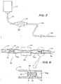
- Figure 7 shows a fluid source, pumping chamber and fluid feed line arrangement which is connectable with the device of Figure 3,
- Figure 8 shows a detailed sectional elevation view of the pumping chamber portion of the arrangement shown in .Figure 7,-and
- Figure 9 shows a schematic circuit diagram of electrical components which are incorporated in the pump device of Figure 3.
- The fluid pump device as shown in Figures 1 and 2 comprises a
housing 10 which is partitioned to provide fourseparate compartments compartment 11 houses a container 15 of fluid which is to be pumped into and from afluid feed line 16 which is coupled to a hypodermic-type needle 17. The needle is intended to be inserted into a patient to whom the fluid is to be administered. The container 15 is formed from an elastic or deformable material, so that its volume will reduce as fluid is withdrawn and so as to avoid the creation of a partial vacuum within'the container with extraction of its contents. - The
compartment 12 housesbatteries 18 which provide electrical energy to the below mentioned elements of the device, thecompartment 13 contains electrical circuitry associated with the device, and thecompartment 14 contains apumping chamber 19. - The pumping chamber 19 (which is illustrated in greater detail in Figure 2) comprises an
elongate tube 20 which is formed from an elastic material (e.g. silicon rubber) and which is fitted at both ends withunidirectional valve members respective valve seats helical compression springs 25 and 26. - A
pulse detector chamber 27 is also located within thecompartment 14, such chamber being constructed in much the same manner as thepumping chamber 19 but not being fitted with valve members. - The two
chambers compartment 14 betweenrespective clamp elements fluid delivery line 32. The,pulse detector chamber 27 is connected with thefluid line 16. - Also located within the
compartment 14 is asolenoid device 33 which includes a pivotably mountedarmature 34. The armature is connected to themovable clamp element 29 and, when the solenoid is energised, theclamp element 29 acts against thepumping chamber 19 to effect compression of thetube 20. When the clamping force is applied to thetube 20 the contained volume of the pumping chamber is reduced and fluid within the pumping chamber is expelled past thevalve member 20 and into thepulse detector chamber 27. At the same time, increased pressure within thepumping chamber 19 holds thevalve member 21 in a closed position. Then, when thesolenoid 33 is de-energised, themovable clamp element 29 moves in a direction away from the pumping chamber and the chamber is permitted to resume its original volumetric capacity, this being achieved by virtue of the inherent resiliency of thetube 20. As the volume of the chamber increases and the pressure within the chamber drops, thevalve member 22 is closed and a new charge of fluid is drawn into the pumping chamber from the source 15 by way of thevalve member 21. Once thepumping chamber 19 has been primed, successive energisations of thesolenoid 33 results in successive pulses of fluid being pumped through the device. - The
clamp element 31 is a movable element and is permanently biased against theelastic tube 34 of thepulse detector chamber 27. Also, theclamp element 31 is coupled to atransducer 35 which detects for movement of theclamp element 31 and which provides an electrical output to electric logic circuitry. Such circuitry is not shown in the drawings but is contained within thecompartment 13 and operates in the following manner: - If air is contained within the pumping chamber '19, when the
solenoid 33 is actuated it will function only to compress the air and, with appropriate force applied to thevalve member 22 by the spring 26, the air will not be pumped into thechamber 27. Thus, theclamp element 31 will not be moved outwardly to any significant extent (as it would otherwise be if a pulse of fluid were to be pumped into the chamber 27), and the absence of significant movement of the clamp element 3i will result in a zero or low output from thetransducer 35. Such output is fed to an alarm device (not shown) by the logic circuitry to indicate the existence of an air'bubble in the pumping chamber and to disabling circuitry associated with the solenoid energisation circuit. - If a blockage occurs in the
feed line 16, when the solenoid is actuated to pump fluid into thepulse detector chamber 27 the fluid will be subjected to forward resistance and will tend to expand thetube 34 of thechamber 27 to an abnormal extent and thereby cause greater-than-normal movement of theclamp element 31. Such movement will be imparted to thetransducer 35 and will result in a high level output signal from the transducer. The high level output signal will then be fed to the logic circuitry to indicate the existence of a line blockage and to the disabling circuitry associated with the solenoid. - Reference is now made to Figures 3 to 9 of the drawings and hence to the second embodiment of the pump device.
- In this case, the pump device comprises a casing 40 having an
oblong housing 41 and a removable rear cover which is absent from the casing as shown in Figure 4. The casing 40 does not house a pumping chamber or fluid source (in contrast with the previously described embodiments) but, rather, a pumpingchamber 42 and associatedfeed line 43 is mounted to thefront face 44 of the casing as indicated by the dotted outline in Figure 3. - As shown in Figure 3, two generally U-shaped support elements 4.5 are fitted or moulded onto the front face of the
casing 41 and are used to hold thefeed line 43 in situ. Also, afirst opening 46 is formed in the face of the casing and through which fixed andmovable clamp elements - A
second opening 49 is also formed in thefront face 44 of the casing and through which a pulserate selector device 50 projects. Theselector device 50 is connected with electrical circuitry which is to be hereinafter described and it has elements which can be turned manually to "dial-up" a required number of "pulses per minute" to be delivered to a solenoid which is to be hereinafter referred to. As illustrated, the selector device is set to initiate 60 energisations per minute of the solenoid. Additionally, a main ON-OFF switch 51 is mounted to thefront face 44 of the casing, as are a series of four indicator lamps. The lamps illuminate to indicate the conditions which are designated by the indicia which is marked or inscribed on the front face of the casing as shown in Figure 3. Finally, the front face of the casing is fitted with an alarm reset (push-button) switch 52 as indicated in Figure 3. - Within the
casing 41 and as viewed in Figure 4 are a battery compartment 41a, two printedcircuit boards 41b and 41c and electric circuit components (not specifically shown) which are mounted to the printed circuit boards. Additionally, located behind thecircuit board 55 and as shown in Figure 5 are theselector device 50, theswitch 51 and asolenoid 53. - As shown in Figures 5 and 6, the solenoid comprises a
yoke 54, acoil 55 which is mounted to the yoke and an L-shapedarmature 56 which is pivotably mounted to the yoke by a resilientflat plate 57. Also, the fixedclamp element 47 is mounted to or extends from theyoke 54 and themovable clamp element 48 is mounted to the armature, both of the clamp elements projecting through theopening 46 in thefront face 44 of the casing to the position shown in Figure 3. When the solenoid is energised, thearmature 56 of the solenoid moves to cause themovable clamp element 48 to move in a direction away from the fixedclamp element 47. - An
extension arm 58 of the armature is connected to onewall 59 of the casing by ahelical tension spring 60, and the spring acts normally to bias thearmature 56 to an open position and hence to bias themovable clamp element 48 in a direction toward the fixedclamp element 47. Thus, successive energisation and de-energisation of the solenoid causes the pumping chamber 42 (Figure 1) to be expanded and compressed between theclamp elements - A
screw connection 61 is made between thespring 60 and thehousing wall 59 to permit adjustment of the effective length of the spring and, therefore, to permit adjustment of the force exerted on theextension arm 58 by the spring. - A pair of oppositely directed moving
contacts 62 and 63 are formed on theextension arm 58 for contacting fixedcontacts 64 and 65 respectively. The contacts 62 and 64 are normally closed (when the solenoid is not energised) and thecontacts screw connector 66. - The pumping
chamber 42 andfeed line 43 are shown in Figure 7 in association with other components which might be considered collectively as forming a patient circuit. Thus, the pumpingchamber 42 is connected (or connectable) to asource 67 of injectable fluid and to ahypodermic type needle 68 by thefeed line 43. - As best seen from Figure 8, the pumping
chamber 42 comprises atube 70 which is formed from an elastic material (as in the case of the previously described . embodiment) and the tube is formed adjacent each end thereof with athroat portion 71. Avalve member 72a is located in each of thethroats 71. Each valve member has ahead 72 which normally closes against aseat 73, a cruciform- shapedtail 74 through which fluid may pass and a connectingstem 75. The two valve members are formed from a resilient material and they function to permit fluid to pass only in the direction indicated by thearrow 76. Thus, when the solenoid is energised and theclamp element 48 moves away fromelement 47, the pumping chamber is expanded to permit fluid flow into the chamber, and, when the solenoid is de-energised and theclamp element 48 moves toward theelement 47, the pumping chamber is compressed so as to expel contained fluid. The spacial relationship of theclamp elements pumping chamber 42. - A description is now provided in respect of the use and operation of the pump device, the description being given with reference to Figures 3 to 8 and, where appropriate, to the circuit diagram of Figure 9.
- Firstly, a pre-sterilised "patient circuit" comprising the pumping
chamber 42feed line 43 andhypodermic needle 68 is connected to thesource 67 of injectable material. - Secondly and prior to fitting of the "patient circuit" to the fluid pump device, the pumping
chamber 42 is operated manually so as to pump fluid into the pumping chamber and feed line and so as to expel all air from the patient circuit. This operation is necessary before fitting the patient circuit to the pump device because such device will not in fact operate to clear the system of air and, whilst any air exists in the system, the pump device will indicate a'fault condition. This because the pumping chamber does not have its contained volume reduced to zero during successive operations of the solenoid whereas this operation can be-performed manually. In fact, the pump device is designed such that total compression of the pumping chamber is not effected during normal operation of the device, so that detection might be made for the presence of any unwanted air bubbles which may enter the pumping chamber. - Thirdly, after clearing all air from the patient circuit, this being indicated when fluid is expelled from the
hypodermic needle 68, the pumpingchamber 42 is mounted to the pump device as indicated in Figure 3. - Fourthly, the device is then switched on. This operation does not of itself result in energisation of the
solenoid 53 but, to enable a check to be made on the alarm circuits, it should cause illumination of the fault condition indicator lamps (Figures 3 and 9). Also, an audible alarm is initiated. A logic circuit which is shown in Figure 9 and which is hereinaftered referred to controls these functions. - Fifthly, the
alarm reset button 52 is pressed and, if no faults exist in the system, successive energisations of the solenoid will occur to result in the pumping of fluid through the patient circuit. - Sixthly, the device is switched-off and a desired infusion rate (i.e. energising pulse repetition rate to the solenoid) is selected by "dialing-up" the appropriate number on the
selector device 50. Typically, the pulse repetition rate may be selected somewhere in the range of one pulse per minute to one hundred pulses per minute. - Thereafter, the hypodermic needle is inserted in the patient and the pump device is again switched-on, following the procedures of steps numbered four and 5.
- Although not shown in the drawings, means such as a "total" pulse counter may be incorporated in the pump device to automatically switch-off the device following the occurrence of a predetermined number of energisations of the solenoid. In any case, if the device is not switched-off before the
source 67 is depleted of all fluid the pump will automatically switch-off because a fault condition (i.e. no fluid in the pumping chamber 42) will be sensed, as hereinafter mentioned. - The operation of the pump device under fault conditions will be described below with reference to the description which is now given in respect of the electrical circuitry associated with the device and as shown in Figure 9 of the . drawings.
- A pulse generator 80 is powered from the power supply (batteries) 81 by way of the
switch 51. The pulse generator produces a train of square-wave pulses, with each pulse having a width of approximately 40 ms. However this pulse width may be different in pump devices which are intended for different applications or it may be selectively variable. - The output from the pulse generator is applied to a
divider network 82 which is controlled to provide a selected pulse repetition rate output by the selector device 50 (see also Figure 1). The pulse repetition rate might typically be selected to fall within the range of 1 pulse per minute to 100 pulses per minute. The output of the divider is amplified in adriver 83 and the output of the driver is applied to thesolenoid coil 55. - A
logic circuit 84 which is controlled by pulses from the pulse generator has input derived from the normally open and normally closedcontacts 64 and 65, and one output from the logic circuit is employed to illuminatelamps 85 with each excitation pulse applied to the solenoid. Alternatively and in the event that the solenoid is not energised, another output will be derived from the logic circuit to illuminate the lamp 86. - When the
solenoid 55 is energised theclamp element 47 is moved in a direction away from theelement 46, the normally closed contacts 62, 64 open and the normallyopen contacts spring 60 causes movement of theclamp element 47 toward theelement 46 and re-establishment of the normally open and normally closed contact relationship. The time occupied in restoration of this relationship is measured bytimers - If air is present in the
pumping chamber 42 or if the -feed line 43 to the pumping chamber is blocked or if no fluid is available for delivery to the pumping chamber or if the pumping chamber is not properly inserted between theclamp elements clamp element 47 by the pumpingchamber 42 and theelement 47 will close more quickly than a predetermined time period T. Conversely, if a block occurs in thefeed line 43 to the patient, a pressure build-up will occur in thepumping chamber 42 and a greater-than-normal resistance will be exerted against closure of theclamp element 47. Thus theclamp element 47 will close more slowly than the predetermined time interval T. - The
timers clamp element 47 and the time- related output signals from thetimers comparators clamp element 47 is less than the predetermined time T theindicator lamp 91 will be illuminated, and if the closing time for the clamp element is greater than the predetermined time T theindicator lamp 92 will be illuminated. - Illumination of any one of the
lamps audible alarm 93. Additionally, the existence of a fault condition causes disabling of the pulse generator 80 by way of disabling system 94. - As above mentioned, at the time of initial switch-on - of-the pump device, the logic circuitry causes excitation- of the fault indicating lamps, to enable a check to be made on the operation of such lamps, and the alarm reset
push button 52 is provided for resetting the disabling network and initiating operation of the pulse generator if no fault condition does in fact exist in the system.
Claims (12)
Applications Claiming Priority (2)
| Application Number | Priority Date | Filing Date | Title |
|---|---|---|---|
| AU8632/79 | 1979-05-04 | ||
| AUPD863279 | 1979-05-04 |
Publications (2)
| Publication Number | Publication Date |
|---|---|
| EP0018649A1 true EP0018649A1 (en) | 1980-11-12 |
| EP0018649B1 EP0018649B1 (en) | 1983-12-28 |
Family
ID=3768088
Family Applications (1)
| Application Number | Title | Priority Date | Filing Date |
|---|---|---|---|
| EP80102392A Expired EP0018649B1 (en) | 1979-05-04 | 1980-05-02 | Fluid pump |
Country Status (7)
| Country | Link |
|---|---|
| US (1) | US4558989A (en) |
| EP (1) | EP0018649B1 (en) |
| JP (1) | JPS5612084A (en) |
| CA (1) | CA1149672A (en) |
| DE (1) | DE3065981D1 (en) |
| ES (1) | ES8102811A1 (en) |
| ZA (1) | ZA802574B (en) |
Cited By (7)
| Publication number | Priority date | Publication date | Assignee | Title |
|---|---|---|---|---|
| EP0053437A1 (en) * | 1980-11-28 | 1982-06-09 | Novacor Medical Corporation | Pump and actuator mechanism |
| EP0062974A1 (en) * | 1981-04-10 | 1982-10-20 | Parker Hannifin Corporation | Medication injection device |
| EP0063727A3 (en) * | 1981-04-15 | 1985-05-02 | Wellcome Australia Limited | Fluid pump |
| EP0177250A3 (en) * | 1984-10-01 | 1988-02-03 | Cook Incorporated | Implantable insulin administration device |
| WO1993010830A1 (en) * | 1991-12-06 | 1993-06-10 | Block Medical, Inc. | Programmable infusion pump |
| WO1995003079A1 (en) * | 1993-07-20 | 1995-02-02 | Volker Lang | Infusion monitoring device |
| EP3488879A1 (en) | 2017-11-23 | 2019-05-29 | Medela Holding AG | Sensor arrangement for detecting a fluid flow |
Families Citing this family (10)
| Publication number | Priority date | Publication date | Assignee | Title |
|---|---|---|---|---|
| JPS6094912A (en) * | 1983-10-28 | 1985-05-28 | Masashige Suzuki | Body neutral fat reducing agent |
| FR2565882B2 (en) * | 1984-06-13 | 1987-09-18 | Centre Nat Rech Scient | CONNECTION DEVICE WITH MULTIPLE DEGREES OF FREEDOM |
| GB8825816D0 (en) | 1988-11-04 | 1988-12-07 | Danby Medical Eng Ltd | Pumping device |
| CA2278239C (en) | 1997-01-17 | 2003-12-23 | Niagara Pump Corporation | Linear peristaltic pump |
| FR2834442B1 (en) * | 2002-01-07 | 2004-10-08 | Saphir Medical | APPARATUS FOR MICRODOSE INJECTION OF AN ACTIVE PRODUCT BY PRESSURE WORKING LIQUID JETS AND METHOD FOR GENERATING A SEQUENCE OF LIQUID JETS USING THE SAME |
| US20030181865A1 (en) * | 2002-03-21 | 2003-09-25 | Kent Abrahamson | Pump and tube set thereof |
| US6942473B2 (en) * | 2002-03-21 | 2005-09-13 | Hospira, Inc. | Pump and tube set thereof |
| US7399401B2 (en) * | 2002-10-09 | 2008-07-15 | Abbott Diabetes Care, Inc. | Methods for use in assessing a flow condition of a fluid |
| US8585649B2 (en) | 2010-12-16 | 2013-11-19 | Carefusion 303, Inc. | Tubular pumping element |
| US20230125495A1 (en) * | 2021-10-25 | 2023-04-27 | Carefusion 303, Inc. | Mini peristaltic pump |
Citations (7)
| Publication number | Priority date | Publication date | Assignee | Title |
|---|---|---|---|---|
| DE2543185A1 (en) * | 1975-08-08 | 1977-02-10 | Ami Ginier | Peristaltic pump with delivery control unit - has timing cycle generator connected in series to preselection and control units for cyclic delivery |
| FR2337824A1 (en) * | 1976-01-12 | 1977-08-05 | Vial Sarl | High frequency medical drip feed pump - has sealing valve downstream of electromagnetically operated pumping piston |
| FR2344298A1 (en) * | 1976-03-16 | 1977-10-14 | Vial Sarl | Precise control of drip feed for medical perfusion etc. - uses electromagnet to actuate two tube compression valve clamps |
| GB2000833A (en) * | 1977-07-05 | 1979-01-17 | Andros Inc | Medical infusion system |
| DE2832800A1 (en) * | 1977-07-27 | 1979-02-15 | Koken Co | INJECTION DEVICE |
| GB2020735A (en) * | 1978-05-10 | 1979-11-21 | Fresenius Chem Pharm Ind | Hose pump having a high dosing accuracy |
| EP0012389A1 (en) * | 1978-12-08 | 1980-06-25 | Josef Hirschmann | Infusion device |
Family Cites Families (9)
| Publication number | Priority date | Publication date | Assignee | Title |
|---|---|---|---|---|
| US2351828A (en) * | 1942-01-08 | 1944-06-20 | G L Meyers | Surgical pump |
| JPS436350Y1 (en) * | 1964-03-03 | 1968-03-21 | ||
| DE1503464A1 (en) * | 1966-01-10 | 1969-07-17 | Ladislaus Unger | Electrically driven conveyor system |
| US3349716A (en) * | 1966-03-28 | 1967-10-31 | Weber George Hunt | Pumps |
| US3620650A (en) * | 1969-12-05 | 1971-11-16 | Robert F Shaw | Gas-disabled liquid-pumping apparatus |
| US3985133A (en) * | 1974-05-28 | 1976-10-12 | Imed Corporation | IV pump |
| US4047844A (en) * | 1975-12-08 | 1977-09-13 | Searle Cardio-Pulmonary Systems Inc. | Blood pumping system |
| US4277226A (en) * | 1979-03-09 | 1981-07-07 | Avi, Inc. | IV Pump with empty supply reservoir and occlusion detector |
| US4411652A (en) * | 1981-08-21 | 1983-10-25 | The Regents Of The University Of California | Internally sterile pulsatile infusor system |
-
1980
- 1980-04-29 ZA ZA00802574A patent/ZA802574B/en unknown
- 1980-05-02 CA CA000351157A patent/CA1149672A/en not_active Expired
- 1980-05-02 DE DE8080102392T patent/DE3065981D1/en not_active Expired
- 1980-05-02 JP JP5802180A patent/JPS5612084A/en active Pending
- 1980-05-02 EP EP80102392A patent/EP0018649B1/en not_active Expired
- 1980-05-02 ES ES491131A patent/ES8102811A1/en not_active Expired
-
1984
- 1984-07-12 US US06/630,339 patent/US4558989A/en not_active Expired - Fee Related
Patent Citations (7)
| Publication number | Priority date | Publication date | Assignee | Title |
|---|---|---|---|---|
| DE2543185A1 (en) * | 1975-08-08 | 1977-02-10 | Ami Ginier | Peristaltic pump with delivery control unit - has timing cycle generator connected in series to preselection and control units for cyclic delivery |
| FR2337824A1 (en) * | 1976-01-12 | 1977-08-05 | Vial Sarl | High frequency medical drip feed pump - has sealing valve downstream of electromagnetically operated pumping piston |
| FR2344298A1 (en) * | 1976-03-16 | 1977-10-14 | Vial Sarl | Precise control of drip feed for medical perfusion etc. - uses electromagnet to actuate two tube compression valve clamps |
| GB2000833A (en) * | 1977-07-05 | 1979-01-17 | Andros Inc | Medical infusion system |
| DE2832800A1 (en) * | 1977-07-27 | 1979-02-15 | Koken Co | INJECTION DEVICE |
| GB2020735A (en) * | 1978-05-10 | 1979-11-21 | Fresenius Chem Pharm Ind | Hose pump having a high dosing accuracy |
| EP0012389A1 (en) * | 1978-12-08 | 1980-06-25 | Josef Hirschmann | Infusion device |
Cited By (9)
| Publication number | Priority date | Publication date | Assignee | Title |
|---|---|---|---|---|
| EP0053437A1 (en) * | 1980-11-28 | 1982-06-09 | Novacor Medical Corporation | Pump and actuator mechanism |
| EP0062974A1 (en) * | 1981-04-10 | 1982-10-20 | Parker Hannifin Corporation | Medication injection device |
| EP0063727A3 (en) * | 1981-04-15 | 1985-05-02 | Wellcome Australia Limited | Fluid pump |
| EP0177250A3 (en) * | 1984-10-01 | 1988-02-03 | Cook Incorporated | Implantable insulin administration device |
| WO1993010830A1 (en) * | 1991-12-06 | 1993-06-10 | Block Medical, Inc. | Programmable infusion pump |
| WO1995003079A1 (en) * | 1993-07-20 | 1995-02-02 | Volker Lang | Infusion monitoring device |
| US5688244A (en) * | 1993-07-20 | 1997-11-18 | Lang; Volker | Apparatus for monitoring infusion |
| EP3488879A1 (en) | 2017-11-23 | 2019-05-29 | Medela Holding AG | Sensor arrangement for detecting a fluid flow |
| WO2019101640A1 (en) | 2017-11-23 | 2019-05-31 | Medela Holding Ag | Sensor arrangement for detecting a flow of fluid |
Also Published As
| Publication number | Publication date |
|---|---|
| DE3065981D1 (en) | 1984-02-02 |
| CA1149672A (en) | 1983-07-12 |
| ES491131A0 (en) | 1981-02-16 |
| ZA802574B (en) | 1981-04-29 |
| JPS5612084A (en) | 1981-02-05 |
| ES8102811A1 (en) | 1981-02-16 |
| EP0018649B1 (en) | 1983-12-28 |
| US4558989A (en) | 1985-12-17 |
Similar Documents
| Publication | Publication Date | Title |
|---|---|---|
| US4558989A (en) | Fluid pump | |
| CA1064792A (en) | Intravenous and intra arterial delivery system | |
| US4105028A (en) | Positive control intravenous fluid administration | |
| US3890968A (en) | Fluid flow control means | |
| EP0063727A2 (en) | Fluid pump | |
| EP0058167B1 (en) | Metering apparatus with downline pressure monitoring system | |
| US5080648A (en) | Hypodermic fluid dispenser | |
| US5423746A (en) | Method and apparatus for infiltration detection during administration of intravenous fluids | |
| US5250027A (en) | Peristaltic infusion device with backpack sensor | |
| US7641629B2 (en) | Breast pump | |
| US4850807A (en) | Disposable cassette for fluid delivery pump systems | |
| US4845487A (en) | Pump system for enteral/parenteral fluid control and delivery | |
| US3731679A (en) | Infusion system | |
| US3425415A (en) | Controlled infusion system | |
| US4842584A (en) | Disposable fluid infusion pumping chamber cassette and drive mechanism thereof | |
| GB1594217A (en) | Method and apparatus for controlling intravenous administration of fluid to a patient | |
| US4261356A (en) | Method and apparatus for controlling the dispensing of fluid | |
| CN100586495C (en) | Actuator system comprising lever mechanism | |
| EP0062037B1 (en) | Metering apparatus having rate compensation circuit | |
| EP0184391A2 (en) | Sequence valve for piggyback IV administration | |
| MXPA05004072A (en) | Medical cassette pump with single force sensor to determine the operating status. | |
| EP0316428B1 (en) | Hypodermic fluid dispenser | |
| AU603526B2 (en) | Pump system for enteral/parenteral fluid control and delivery | |
| WO1985004813A1 (en) | A pump | |
| NZ193550A (en) | Electrically driven variable chamber volume pump: detection of air bubbles and pressure blockages |
Legal Events
| Date | Code | Title | Description |
|---|---|---|---|
| PUAI | Public reference made under article 153(3) epc to a published international application that has entered the european phase |
Free format text: ORIGINAL CODE: 0009012 |
|
| AK | Designated contracting states |
Designated state(s): BE DE FR GB IT NL |
|
| 17P | Request for examination filed |
Effective date: 19810508 |
|
| ITF | It: translation for a ep patent filed | ||
| GRAA | (expected) grant |
Free format text: ORIGINAL CODE: 0009210 |
|
| AK | Designated contracting states |
Designated state(s): BE DE FR GB IT NL |
|
| REF | Corresponds to: |
Ref document number: 3065981 Country of ref document: DE Date of ref document: 19840202 |
|
| ET | Fr: translation filed | ||
| PGFP | Annual fee paid to national office [announced via postgrant information from national office to epo] |
Ref country code: DE Payment date: 19840526 Year of fee payment: 5 |
|
| PGFP | Annual fee paid to national office [announced via postgrant information from national office to epo] |
Ref country code: BE Payment date: 19840630 Year of fee payment: 5 |
|
| PLBE | No opposition filed within time limit |
Free format text: ORIGINAL CODE: 0009261 |
|
| STAA | Information on the status of an ep patent application or granted ep patent |
Free format text: STATUS: NO OPPOSITION FILED WITHIN TIME LIMIT |
|
| 26N | No opposition filed | ||
| PGFP | Annual fee paid to national office [announced via postgrant information from national office to epo] |
Ref country code: NL Payment date: 19870531 Year of fee payment: 8 |
|
| PG25 | Lapsed in a contracting state [announced via postgrant information from national office to epo] |
Ref country code: GB Effective date: 19890502 |
|
| PG25 | Lapsed in a contracting state [announced via postgrant information from national office to epo] |
Ref country code: BE Effective date: 19890531 |
|
| PGFP | Annual fee paid to national office [announced via postgrant information from national office to epo] |
Ref country code: FR Payment date: 19891130 Year of fee payment: 10 |
|
| PG25 | Lapsed in a contracting state [announced via postgrant information from national office to epo] |
Ref country code: NL Effective date: 19891201 |
|
| GBPC | Gb: european patent ceased through non-payment of renewal fee | ||
| NLV4 | Nl: lapsed or anulled due to non-payment of the annual fee | ||
| PG25 | Lapsed in a contracting state [announced via postgrant information from national office to epo] |
Ref country code: DE Effective date: 19900201 |
|
| PG25 | Lapsed in a contracting state [announced via postgrant information from national office to epo] |
Ref country code: FR Effective date: 19910131 |
|
| REG | Reference to a national code |
Ref country code: FR Ref legal event code: ST |