EP0018207B1 - Pressure monitoring system for electrofluidic sensing devices - Google Patents
Pressure monitoring system for electrofluidic sensing devices Download PDFInfo
- Publication number
- EP0018207B1 EP0018207B1 EP80301235A EP80301235A EP0018207B1 EP 0018207 B1 EP0018207 B1 EP 0018207B1 EP 80301235 A EP80301235 A EP 80301235A EP 80301235 A EP80301235 A EP 80301235A EP 0018207 B1 EP0018207 B1 EP 0018207B1
- Authority
- EP
- European Patent Office
- Prior art keywords
- pressure
- fluid
- sensing device
- supplied
- supply
- Prior art date
- Legal status (The legal status is an assumption and is not a legal conclusion. Google has not performed a legal analysis and makes no representation as to the accuracy of the status listed.)
- Expired
Links
- 238000012544 monitoring process Methods 0.000 title claims abstract description 63
- 239000012530 fluid Substances 0.000 claims abstract description 73
- 238000013022 venting Methods 0.000 claims description 8
- 230000000007 visual effect Effects 0.000 claims description 6
- 125000004122 cyclic group Chemical group 0.000 claims description 5
- 238000005086 pumping Methods 0.000 claims 1
- 238000007917 intracranial administration Methods 0.000 description 19
- QSHDDOUJBYECFT-UHFFFAOYSA-N mercury Chemical compound [Hg] QSHDDOUJBYECFT-UHFFFAOYSA-N 0.000 description 10
- 229910052753 mercury Inorganic materials 0.000 description 10
- 238000000034 method Methods 0.000 description 8
- XLYOFNOQVPJJNP-UHFFFAOYSA-N water Substances O XLYOFNOQVPJJNP-UHFFFAOYSA-N 0.000 description 7
- 238000010586 diagram Methods 0.000 description 5
- 230000001276 controlling effect Effects 0.000 description 4
- 239000007787 solid Substances 0.000 description 4
- 230000008901 benefit Effects 0.000 description 3
- 210000003625 skull Anatomy 0.000 description 3
- 230000003750 conditioning effect Effects 0.000 description 2
- 230000007812 deficiency Effects 0.000 description 2
- 238000001514 detection method Methods 0.000 description 2
- 239000000835 fiber Substances 0.000 description 2
- 230000006872 improvement Effects 0.000 description 2
- 238000002955 isolation Methods 0.000 description 2
- 230000007246 mechanism Effects 0.000 description 2
- 230000001105 regulatory effect Effects 0.000 description 2
- 238000001356 surgical procedure Methods 0.000 description 2
- 206010020509 Hydrocephalic conditions Diseases 0.000 description 1
- 238000009825 accumulation Methods 0.000 description 1
- 238000013459 approach Methods 0.000 description 1
- 238000009530 blood pressure measurement Methods 0.000 description 1
- 230000006931 brain damage Effects 0.000 description 1
- 231100000874 brain damage Toxicity 0.000 description 1
- 208000029028 brain injury Diseases 0.000 description 1
- 239000000872 buffer Substances 0.000 description 1
- 239000003990 capacitor Substances 0.000 description 1
- 230000008859 change Effects 0.000 description 1
- 230000000295 complement effect Effects 0.000 description 1
- 230000003247 decreasing effect Effects 0.000 description 1
- 230000002950 deficient Effects 0.000 description 1
- 230000000994 depressogenic effect Effects 0.000 description 1
- 238000002347 injection Methods 0.000 description 1
- 239000007924 injection Substances 0.000 description 1
- 239000003562 lightweight material Substances 0.000 description 1
- 238000005259 measurement Methods 0.000 description 1
- 238000012806 monitoring device Methods 0.000 description 1
- 230000003287 optical effect Effects 0.000 description 1
- 239000013618 particulate matter Substances 0.000 description 1
- 229920001296 polysiloxane Polymers 0.000 description 1
- 235000020004 porter Nutrition 0.000 description 1
- 230000004044 response Effects 0.000 description 1
- 239000004065 semiconductor Substances 0.000 description 1
- 230000000087 stabilizing effect Effects 0.000 description 1
- 238000012360 testing method Methods 0.000 description 1
Images



Classifications
-
- G—PHYSICS
- G01—MEASURING; TESTING
- G01L—MEASURING FORCE, STRESS, TORQUE, WORK, MECHANICAL POWER, MECHANICAL EFFICIENCY, OR FLUID PRESSURE
- G01L11/00—Measuring steady or quasi-steady pressure of a fluid or a fluent solid material by means not provided for in group G01L7/00 or G01L9/00
-
- A—HUMAN NECESSITIES
- A61—MEDICAL OR VETERINARY SCIENCE; HYGIENE
- A61B—DIAGNOSIS; SURGERY; IDENTIFICATION
- A61B5/00—Measuring for diagnostic purposes; Identification of persons
- A61B5/03—Measuring fluid pressure within the body other than blood pressure, e.g. cerebral pressure ; Measuring pressure in body tissues or organs
- A61B5/031—Intracranial pressure
-
- G—PHYSICS
- G01—MEASURING; TESTING
- G01L—MEASURING FORCE, STRESS, TORQUE, WORK, MECHANICAL POWER, MECHANICAL EFFICIENCY, OR FLUID PRESSURE
- G01L7/00—Measuring the steady or quasi-steady pressure of a fluid or a fluent solid material by mechanical or fluid pressure-sensitive elements
Definitions
- the present invention relates to a pressure monitoring system and, more particularly, concerns such a system for use with electrofluidic devices for sensing pressure, such as devices for monitoring intracranial pressure within the skull of a patient, and the like devices.
- the accumulation of data relating to pressure measurements of various areas of a patient before, during and after surgery is heavily relied upon in order to provide a satisfactory understanding of the patient's tendencies.
- the monitoring of intracranial pressure in patients who have undergone neurosurgery or who have hydrocephalic conditions provides the medical staff with information on the trends of pressure levels and serves as a clear indication should the intracranial pressure rise to levels which could cause brain damage or worse.
- One technique for monitoring pressure which is particularly amenable to procedures of intracranial pressure monitoring includes the employment of a device known as a Numoto switch.
- the Numoto switch is a pressure-actuated device generally constructed of a thin, flat flexible envelope and a pair of electrodes inside the envelope usually attached to the flat walls of the envelope and movable so that, depending upon the pressure inside the envelope, they may either contact each other or move away from each other.
- An electrical lead is connected to each electrode to provide an electrical connection therefor.
- a flexible air tube is generally connected to the envelope both for providing air, or other fluids, into the envelope and for enclosing the electrical leads which extend therethrough.
- the Numoto switch is connected to a fluid source for providing fluid into the envelope and also for indicating the pressure level of the supplied fluid.
- the ohmmeter When the pressure inside the envelope just exceeds the intracranial pressure, the walls of the envelope are forced apart, whereupon the electrodes separate, and electrical contact is broken. Once again, through the electrical leads, the ohmmeter provides an indication that electrical contact has been broken inasmuch as the ohmmeter indicator should now read zero. At this point, the operator reads the pressure level of the injected fluid on the manometer. The balance of applied pressure and fluid inside the envelope is maintained by the operator alternately withdrawing and injecting fluid from the reservoir into the envelope, causing the electrical contacts to close and open with this alternating procedure.
- the pressure in the sensor therefore varies continuously, or hunts, around the ambient intracranial pressure.
- the pressure is read off from a manometer or a chart recorder whose pen is connected to the manometer.
- the envelope In use, the envelope is always inflated and is not vented to ambient atmospheric pressure. There is no indication that any more than one sensor could be connected to the control means or that the control means performs any function other than controlling the pressure in the envelope.
- a pressure monitoring system for use with electrofluidic devices for sensing pressure comprises means for supplying fluid to the electrofluidic sensing devices.
- the system includes means for controlling the supply of fluid to the sensing devices responsive to the external pressure level applied to the sensing devices, and to cyclically cause the supplied pressure to vent at each occurrence when the pressure of supplied fluid inside the sensing devices is substantially equal to the applied external pressure, whereupon the fluid supplied to the devices is started again in cyclic fashion.
- Means for detecting the pressure level of the supplied fluid is provided, and there is means for displaying the analogous detected pressure level during supply of the fluid.
- an electrical switching circuit controls the supply of fluid to the sensing devices.
- the means for detecting the pressure level of the supplied fluid is a transducer adapted to convert the detected pressure level into an analog voltage signal.
- the display means is a digital display meter which receives the analog voltage signal from the transducer and numerically displays a numerical voltage reading corresponding to the maximum detected pressure level of the supplied fluid for a short period of time commencing at each instant when the supply of fluid to the sensing devices is terminated.
- This preferred embodiment is designed for use with a plurality of electrofluidic sensing devices and includes a selection mechanism having positions thereon to correspond with the individual sensing devices to which fluid is supplied.
- the preferred embodiment of this invention includes a pre-selectable maximum pressure level for the supplied fluid associated with the switching circuit so that when the level of the supplied fiuid exceeds the pre-selected level, the supply of fluid to the sensing device is vented and an alarm activated.
- operable reset means is provided for re-instituting the operation of the monitoring system.
- an automated pressure monitoring system which overcomes the deficiencies noted above with respect to prior art systems for use with electrofluidic pressure sensing devices. It is appreciated that the automatic detection of a pressure balance between applied pressure to the sensing device and an internally generated pressure is not only time saving, but lends accuracy to the system. Rapid results and readings are produced by the system of the present invention, while the digital display meter provides an actual numerical reading rather than the capillary height reading associated with a pressure manometer. In addition, the accuracy of the system is enhanced as the balance of internally generated pressure to an externally-applied pressure is independent of external temperature which could cause inaccuracies if not accounted for.
- an alarm system which serves to indicate to the operator that a pre-selected pressure level has been exceeded; the present system can be made to cease operation of supplying fluid inside the sensing device once the pre-selected pressure level has been exceeded and the alarm activated.
- the present pressure monitoring system allows more than one sensing device to be monitored, since many times the surgeon may rely upon more than one sensing device to accumulate the data which he requires either during or after surgery. With this feature, the automated pressure monitor can scan and control each pressure sensing device in sequence.
- the present invention preferably has the capability for monitoring and controlling only two pressure sensing devices.
- the venting feature of the system provides for the release of supplied fluid from the sensing device to allow the maximum internally generated pressure level to be detected and monitored.
- Other advantages of the present monitoring system are offered as well, such as a feature to change the scale of the digital display meter to read in different units, such as one reading of pressure in millimeters of mercury (mm/Hg) or to read in centimeters of water (cm/H 2 0?: internal calibration elements provide this range control feature.
- a pressure monitoring system 20 particularly useful with electrofluidic devices for sensing pressure.
- One such pressure sensing device 22 is shown connected to pressure monitor 20 by means of flexible tubing 24 which extends between pressure device 22 and an appropriate connection site on the rear panel of the pressure monitor as hereinafter described.
- the pressure monitoring system is essentially enclosed in a housing 25, preferably made from a lightweight material such as molded high-impact plastic. Housing 25 is compact and box-shaped, and includes a handle 26 which may be rotated around pivot pins 28 on the lateral sides of the housing to be used as a front stand or as a handle for carrying the system.
- the controls and main features of this pressure monitoring system are found on a front panel 29 and a rear panel 30.
- Main control switch 31 includes at least five positions for the particular device being described: “OFF,” “STBY,” “MONITOR,” “ZERO,” and “SPAN.” In the “OFF,' position, all functions of the system are inoperative. In “STBY,” power is supplied to the solid state transducer inside the housing for warmup. Approximately five minutes of operation are allowed in this "STBY” mode to stabilize the output of the transducer and to minimize drift of the digital signal in the system. The “MONITOR” position is used after the “STBY” position, and it is in this position that the system is ready for full automatic operation. "MONITOR” is used in conjunction with one pressure sensing device at a time.
- the pressure supply pump inside the housing will immediately operate and the digital display 32 will light, indicating the bias voltage on the solid state transducer. At this time, the reading should be 00.0. If not, digital display meter 32 is adjusted by turning main control switch to "ZERO.” In this position, the transducer is opened to amosphere so that a zero reading adjustment can be performed.
- the "SPAN" position is provided to provide a full scale reading of digital display 32; for instance, the scale in millimeters of mercury (mm/Hg) is generally 0 to 100.0. If the gain of the digital display has changed, the display can be adjusted so that the reading is 100.0 with the system set on "SPAN" position.
- Digital display meter 32 is designed to display a numerical reading of pressure supplied by the pressure monitoring system to pressure sensing device 22.
- the reading on display meter 32 is a numerical voltage substantially equivalent to the detected pressure level of the fluid supplied to the inside of the pressure sensing device 22.
- a scale range switch 34 essentially a two position toggle switch, is utilized to permit the meter to display voltages in two different scale ranges; either centimeters of water or millimeters of mercury.
- a scale light indicator 35 is provided to indicate that the readings are in centimeters of water, while a scale light indicator 36 informs the operator that the display readings are in millimeters of mercury.
- the scale range of the digital meter When the scale range of the digital meter is set in the millimeters of mercury position, the scale is approximately 100.0, whereas in the centimeters of water position, the digital display reads about 135.7, these values being derived from the internal calibration of this system.
- Two operation indicator lights are provided, an inflation indicator 38 which indicates that fluid from the pressure monitor is being supplied to the sensing device since the switch inside the sensing device is closed; a deflation indicator light 39 is provided to indicate that the contact switch inside the pressure sensing device is open and that the mode of operation is in deflation.
- a digital pressure alarm set 40 is provided so that the maximum pressure level for supplied fluid to the pressure sensing device may be pre-selected.
- Pressure alarm set 40 includes a two position adjustable digital potentiometer 41 and 42 which provides a range for the various values to be set. This potentiometer is calibrated on the same scale to correspond to whichever scale is selected for digital display meter 32.
- an alarm indicator 44 lights on the front panel. This alarm light serves as a safety precaution and informs the operator that the internally generated pressure (balancing the applied external pressure to the pressure sensing device) has exceeded the pre-selected alarm level.
- a sensing device selection switch 45 includes three positions thereon, namely one, two and "AUTO.” On positions one or two, only one pressure sensing device will be monitored corresponding to the position selected. However, in the "AUTO" position, two pressure sensing devices will be monitored and controlled sequentially. In operation in the "AUTO" position, the pressure monitoring system will operate only with respect to, for example, the first pressure sensing device whereupon sensing device operation light 46 will be on. After scanning this pressure sensing device for approximately 20 seconds, the pressure monitor sequentially turns to the next pressure sensing device and starts monitoring and controlling it for about the same period of time, whereupon sensing device operation light 48 is lit. These lights inform the operator which of the pressure sensing devices is being monitored.
- the monitoring system alternately monitors and controls two pressure sensing devices. It can be appreciated that the system can be designed to control many more than two devices, with the same sequential operation in mind. For practical purposes, the present invention is concerned only with a two position device with the automatic feature included. Accordingly, the cyclic operation is merely an alternating operation since only two pressure sensing devices are being monitored.
- FIG. 3 wherein rear panel 30 of the pressure monitoring system is illustrated, it can be seen that there is a provision for making a connection for two pressure sensing devices.
- These provisions are generally female sockets 50 which are designated to provide an electrofluidic connection; i.e. it is through this connection that both an electrical connection and a fluidic connection, such as for air or other fluids, is provided.
- Various types of electrofluidic connectors may be employed, preferably with a female socket mounted directly in rear panel 30 of the pressure monitoring system; one typical electrofluidic junction is described in United States Patent No. 3,649,948.
- On this rear panel is a zero adjustment 51 which is used in conjunction with the "ZERO" position on the main control switch on the front panel.
- a zero control potentiometer 51 is provided to make the proper adjustment; a clockwise turn will increase the reading, whereas a counterclockwise turn will decrease the reading until proper balance is achieved.
- a span gain control potentiometer 52 is provided for use in conjunction with the "SPAN" position on the main control switch. For example, on the millimeters of mercury scale, the span reading should read 100.0; if not, the span gain control potentiometer 52 may be adjusted to provide the correct reading.
- a turntable, adjustable control screw 53 is provided to allow variations in the rate fluid supplied to the sensing device; slower or faster rates may be desirable depending upon the specific application of the sensing device.
- An alarm reset button 54 is associated with the alarm indicator light 44 on the front panel and also in conjunction with the maximum pressure alarm level 40 set by the operator beforehand.
- alarm light 44 When alarm light 44 is activated due to the excessive pressure levels generated inside the pressure sensing device, the supplied fluid to the sensing device is vented to atmosphere as a safety precaution. When this occurs, the system will not operate until alarm reset button 54 is depressed. At this time, alarm indicator light 44 will go off, and fluid supply to the pressure sensing device can continue.
- a two position toggle switch 55 provides an optional audible indicator feature. Thus, if the operator of this system would prefer to have an audible alarm signal when the pre-selected pressure level has been reached, the switch may be turned to the "ON" position.
- Reset button 54 will control both visual and audible indicator alarms so that, once they are activated, depression of the reset button will turn both of them off and allow the system to once again become operational.
- Two phone-type jacks are provided one to make an attachment for a recorder output 56, the other for an event output 58.
- Recorder output 56 is designed to provide a direct output signal corresponding to the voltage reading of the display meter so that the monitored pressure levels can be plotted as a function of time.
- Event output 58 is designed to provide a DC signal each time the electrodes make or break contact so that the inflate/deflate mode can be ascertained.
- a fuse 59 is provided for safety purposes while a detachable hospital grade AC cord and plug 60 is provided to make the proper connection to energize the system.
- FIG 4 the major internal fluidic components of this pressure monitoring system are schematically diagrammed so that the correlation between these components, the control features on the front and rear panels, and the functioning of the pressure monitoring system previously described can be understood.
- An air pump 65 is mounted within the housing for the purpose of supplying air to the electrofluidic pressure sensing device connected to the monitoring system.
- This pump is preferably electrically operated, and in conjunction with the electrical switching circuit (as hereinafter more fully described) is designed to supply the air controllably to the pressure sensing device only when the pressure inside the sensing device is less than the external pressure applied to the sensing device, such as during the monitoring of intracranial pressure levels.
- Most of the control circuitry is found on a printed circuit card 66, shown in phantom lines in Figure 4.
- An air valve regulator 68 is connected to air pump 65 through tubing 69 and serves to control the rate of air flow from the pump into the inside of the pressure sensing device. For example, with the pump operating, air is regulated to flow into the sensing device through variable flow restrictor 73 so that the rate of air flow can be controlled by control screw 53 on the rear panel. With this controllable, variable restrictor the fill rate may be varied, for example, from 4 mm/Hg per second to 16 mm/Hg per second, or other rates as desirable and compatible with the flow restrictor.
- air regulator 68 is adapted to assist in stabilizing the selected air flow rate when the pump is operating and to provide the capability of venting the supplied air to atmospheric pressure level when the operation of the pump terminates during its cyclic operation.
- a filter 70 is provided in the tubing system so that particulate matter may be filtered out of the air being pumped into the sensing device.
- the air flow is carried to a series of four solenoids 71 A, B, C and D which operate in conjunction with a transducer 72 (actually mounted on printed circuit card 66) for the purpose of detecting and measuring the levels of pressure being supplied from the air pump to the pressure sensing device, and then convert the measured pressured into an analog voltage signal.
- Pressure transducer 72 is preferably a pressure sensitive solid state transducer capable of producing an output voltage analogous to the level of pressure applied to the transducer. These transducers are well known and may be selected according to the choice of the designer in order to satisfactorily perform the functions of this pressure monitoring system.
- Manifold 75 is an open chamber into which tubing 69 connects to provide interconnection for fluid flow through solenoids 71A, B, C and D.
- each female electrofluidic socket 50 is shown connected by tubing 69 to solenoids 71A, B, C and D.
- One or more electrofluidic pressure sensing device is connected to female sockets 50 and on into the sensing device. Air is supplied to the sensing device until a substantial balance is achieved between internally supplied pressure and externally applied pressure on the sensing device. Inasmuch as the supplied air is plumbed through the various output solenoids and the transducer, the pressure level of the supplied air can be detected by the transducer and converted into an electrical analog signal for display on the digital meter.
- the monitoring system is programmed to alternately scan two pressure sensing devices.
- Pressure sensing device 22 generally includes a fluid inflatable housing 80 with a pair of contact electrodes 81 and 82 inside the housing, with an electrical lead 84 and 85 connected to each electrode.
- Flexible tubing 24 is connected to housing 80 to provide fluid flow into the housing, and also to serve as an enclosure through which electrical leads 84 and 85 extend so that the proper connection can be made to the pressure monitoring system, preferably through an appropriate electrofluidic connector.
- the housing is generally disc-shaped, and is implanted within the skull of a patient such as described in United States Patent No. 3,649,948.
- the intracranial pressure maintains electrodes 81 and 82 in contact with each other inasmuch as the pressure applied externally to the housing equals or exceeds the internal pressure within the housing. With the pressure monitoring system energized, these contacting electrodes serve as a closed switch sending a signal to the switching circuit to cause fluid to be supplied through tubing 24 into housing 80.
- This pressure level increase inside the housing is graphically illustrated by the recorded output of the pressure monitoring system in Figure 7.
- the increasing slope designated by numeral 86 at any given time indicates that the pressure level inside the housing is increasing; the preferred pressure monitoring system provides an inflation rate of approximately 8 millimeters mercury per second (12 centimeters of water per second), controlled by a pre-set through adjustment screw 53 on the rear panel.
- the plotted trace is illustrated in a decreasing slope 89 which indicates that the supplied fluid has been vented to atmosphere and the level of pressure inside the housing will return to atmospheric levels.
- the rate of return to atmospheric pressure levels inside the housing will normally be greater than the metered inflation rate of the sensor as the sensor is vented to atmosphere through the zero valve.
- electrodes 81 and 82 will once again come in contact with each other thereby causing the entire cycle to repeat itself so that, as seen on the plot in Figure 7, a series of peaks 88 will form a locus line indicating the maximum detected pressure level of the fluid supplied to the sensing device.
- the plot of Figure 7 indicates that, for example, the maximum calibrated output of the system is achieved approximately five to six times per minute. It should be pointed out when referring to Figure 7, that this recorded output is only for one pressure sensing device; if two devices were being utilized and the system was set on the "AUTO" mode, one device would be scanned for approximately twenty seconds so that maximum calibrated pressure readings would take place about two times; then, the operation would sequentially move to the next sensing device again for another twenty second scan time allotted.
- digital display meter 32 While Figure 7 traces the measurement of the internally generated pressure as a function of time for recording purposes, during the operation of this system digital display meter 32 would normally provide an instantaneous, current numerical reading of the pressure levels of supplied fluid. It can be appreciated that the numerical values will be changing rather rapidly during the increase of pressure into the housing of the sensing device. Accordingly, digital display meter 32 is designed to maintain the numerical reading at the maximum level achieved when electrodes 81 and 82 become separated; this numerical reading is held for a period of about five seconds at each instant when the supply of fluid to the sensing device is terminated or when the electrodes break contact.
- an observer of the digital meter will be able to read a fixed value on the meter corresponding to the maximum pressure level detected inside the housing which corresponds to the applied external pressure sensed by the sensing device.
- the digital display is designed to hold the maximum reading for a sufficiently generous period of time for the observer to take note or even record such a reading if it is not being plotted by means of the recorded output.
- Sensor Number One 101 and sensor Number Two 102 represent the two electrofluidic pressure sensing devices which the present monitoring system is capable of monitoring, substantially as described above in conjunction with Figs. 5 and 6.
- Air is caused to enter either sensor 101 or sensor 102 by way of the inflate valve 71 B and the electrofluidic select circuit 71 A. Air is applied to sensor 101 or 102 until the electrodes therein break contact as a result of the internally supplied pressure being substantially equivalent to the applied pressure external to the respective sensing device. Air is supplied by means of air pump 65 and controlled by regulator 68 as described previously.
- pressure transducer 72 is measuring and detecting the pressure levels of the supplied air so that the detected pressure level can be converted into an electrical analog signal.
- the peak, hold and deflate circuit 106 locks the digital meter 32 at the pressure level which pressure transducer 72 has detected at the instant the electrodes in the sensing device break contact. This represents the maximum pressure attained inside the sensing device which corresponds to the maximum applied pressure external to the sensing device. This reading is maintained on the digital meter for approximately 5 seconds.
- the peak, hold and deflate circuit 106 opens the zero valve 71 C thereby venting the air inside the sensing device to atmospheric levels.
- inflate valve 71 B controls the air from the air pump to supply air to the appropriate sensor 101 or 102 to sequentially start the cycle over again.
- a conditioning circuit 109 provides the zero and full scale pressure adjustments for the digital meter 32.
- Zero is adjusted by setting the main control switch 31 on the front panel in the "ZERO" position, which opens zero valve 71 C to atmosphere.
- the full-scale air span is adjusted by placing main control switch 31 into the "SPAN” position. Air is regulated to the full scale reading of the digital display meter, for example, 100 millimeters of mercury, precisely by the air regulator 68 and then is supplied to the span valve 71 D or the inflate valve 71 B, depending on whether the main control switch is on the "SPAN" or "MONITOR” position, respectively.
- This full scale regulation serves as an internal reference providing a self-contained feature for full calibration of the monitoring system.
- An alarm set circuit 111 compares the pressure set on the front panel by way of the two position digital potentiometer 41 and 42 with the pressure being displayed on digital meter 32. When the displayed pressure, determined by way of pressure transducer 72, exceeds the preset point on the front panel, alarm set circuit 111 will cause alarm indicator 44, preferably a light-emitting diode, to light thereby providing a visual alarm on the front panel during operation. If the operator has activated switch 55 for the optional audible indicator feature on the rear panel, alarm circuit 111 will also cause an audible alarm 114 in the form of a 1,000 hertz tone.
- a recorder and event output circuit 115 buffers the pressure signal for connection to an external chart recorder, the connection being made through phono-jacks 56 and 58 on the rear panel of the monitoring system. As noted earlier, the event recorder output is provided for examining the peak reading on the plotted chart.
- Auto select circuit 105 is provided in conjunction with selection switch 45 on the front panel to select the monitoring of either sensor 101, sensor 102 or the automatic scan mode for sequentially and alternately monitoring both pressure sensing devices.
- a patient isolation circuit 118 isolates the patient from electrical ground for purposes of safety.
- the electrical circuit diagram illustrates the preferred combination of components to provide the capabilities and functions as described above with reference to Figure 8.
- Most of the components illustrated in Figure 9 are located on'the printed circuit board described in conjunction with Figure 4.
- Switch 31A, 31 B, 31 C and 31 D denote the multi- position control switch 31 on the front panel of the monitoring system.
- Line voltage enters through transformer 122 where it is reduced to 18 volts AC.
- the full wave rectifier 124 and the voltage regulators 125 and 126 generate +15 volts and -15 volts supply voltage for the system.
- the solid state pressure transducer 72 may be a stock component such as National Semiconductor part No. LX1601 G, and is powered from one leg of the +15 volt power supply.
- This transducer is plumbed through various output solenoids 71 A, 71 B, 71 C and 71 D providing a fluidic connection between transducer, pump and one of the pressure sensing devices 1 or 2.
- the output voltage of the transducer analog to the pressure input is then fed into amplifier 132.
- the zero adjust 51 works in conjunction with amplifier 132, providing the user with a method of nulling the zero offset. From here the signal is fed into amplifier 134.
- the output of this amplifier 134 is scaled by the span control 52, providing the user with a method of calibrating the devices span range.
- the output of amplifier 134 is modified by switch 34 to provide a second calibrated measuring unit.
- section 34A provides a signal to turn on light emitting diode 35 indicating the unit is calibrated for measuring centimeters of water.
- switch in other position 34A provides a signal to light emitting diode 36, indicating the unit is calibrated for measuring millimeters of mercury.
- section 34B modifies the output of amplifier 134 by the resistive divider accomplished by 135, 136.
- the output of second stage amplifier 134 is fed into pin No. 5 on the digital panel meter 32, which is located on the front panel of the monitoring system.
- This digital meter may be a standard item such as is presently available from Fairchild Instruments, part No. D.P.M. 300550.
- the adjusted amplified signal is displayed in millivolts equivalent to either millimeters of mercury or centimeters of water.
- the analog output signal is simultaneously fed into alarm set circuit 111 where a digital value of the millivolt signal can be set as a high limit for the system pressure.
- the millivolt signal arrives at the positive input of comparator 149. At this point, its value is compared to the value of the high alarm setting 40 located on front panel.
- Switch 55 (the toggle switch 55 on the rear panel) is provided to include an audible alarm 114 when the switch is closed and when the high pre-level is exceeded.
- Alarm reset 54 allows the audible alarm to be turned off once the system is tripped by the high signal, and also to reset the system for operation and control of the pressure monitoring devices.
- the automatic scanning features of the present system are controlled by means of the integrated circuit device 141, in conjunction with switches 31 D and 45.
- This integrated circuit is available from Signetics Corporation, part No. NE555V, and performs the function indicated by manual/auto sensor select circuit 105 of Fig.
- the peak hold function is accomplished by the circuit including transistor 152, capacitor 153, and resistor 154.
- the digital meter will hold its reading whenever the sensor contacts are open. When the sensor contacts close transistor 152 shuts off. However, the circuit creates a time lag, giving the impression the contacts are still open. This lag is approximately 5 seconds.
- Switch 31 D controls the various positions provided to the main control switch 31 on the front panel and is represented by mode select switch 31 in Fig. 8. Solenoids 71 B, 71 C, 71 D are provided to control the pressure flow in the MONITOR, ZERO and SPAN positions, respectively as selected by way of the main control switch 31.
- switch 45 on the front panel is closed so that the alternating sequence for monitoring the two pressure sensing devices can become operational.
- Solenoid 71 A is provided for this function, and light emitting diodes 46 and 48 indicate which sensing device is being monitored during the sequence.
- inflate valve 71 B is operable to supply air to the sensing device.
- the inflate, deflate mode is also indicated by light emitting diodes 38 and 39, respectively, during the monitoring operation.
- the above described solenoids and associated switches form the electropneumatic sensor select circuit 105.
- the event output circuit 115 receives a signal during the "MONITOR” mode of operation when switch 31 D is closed across the "MONITOR” pole through transistor 145.- In conjunction with phonojack 58 on the rear panel, this circuit is designed to provide a DC signal each time the electrodes inside one of the pressure sensing devices make or break contact. The approximate output level for such signal is 1.5 volts DC.
- the recorder output 115 is associated with both alarm set circuit 111 and digital panel meter 32 since the recorder output provides a direct output of the pressure in millivolts.
- the patient isolation circuit for isolating the patient from ground includes an optical coupler 146 and a low leakage transformer 148 and a relay RLJ with its associated contacts RCJ.
- a pressure monitoring system for use with electrofluidic devices for sensing pressure which automatically detects and displays the amount of pressure being externally applied to the sensing device.
- This monitoring system includes a high pressure alarm indicator to become activated when a pre-set level of pressure has been exceeded by the applied pressure to the sensing device.
Landscapes
- Health & Medical Sciences (AREA)
- Life Sciences & Earth Sciences (AREA)
- Physics & Mathematics (AREA)
- General Physics & Mathematics (AREA)
- Medical Informatics (AREA)
- Molecular Biology (AREA)
- Pathology (AREA)
- Engineering & Computer Science (AREA)
- Biomedical Technology (AREA)
- Heart & Thoracic Surgery (AREA)
- Hematology (AREA)
- Biophysics (AREA)
- Surgery (AREA)
- Animal Behavior & Ethology (AREA)
- General Health & Medical Sciences (AREA)
- Public Health (AREA)
- Veterinary Medicine (AREA)
- Neurosurgery (AREA)
- Measuring Fluid Pressure (AREA)
- Measuring And Recording Apparatus For Diagnosis (AREA)
Abstract
Description
- The present invention relates to a pressure monitoring system and, more particularly, concerns such a system for use with electrofluidic devices for sensing pressure, such as devices for monitoring intracranial pressure within the skull of a patient, and the like devices.
- The accumulation of data relating to pressure measurements of various areas of a patient before, during and after surgery is heavily relied upon in order to provide a satisfactory understanding of the patient's tendencies. For example, the monitoring of intracranial pressure in patients who have undergone neurosurgery or who have hydrocephalic conditions provides the medical staff with information on the trends of pressure levels and serves as a clear indication should the intracranial pressure rise to levels which could cause brain damage or worse. One technique for monitoring pressure which is particularly amenable to procedures of intracranial pressure monitoring includes the employment of a device known as a Numoto switch. The Numoto switch is a pressure-actuated device generally constructed of a thin, flat flexible envelope and a pair of electrodes inside the envelope usually attached to the flat walls of the envelope and movable so that, depending upon the pressure inside the envelope, they may either contact each other or move away from each other. An electrical lead is connected to each electrode to provide an electrical connection therefor. A flexible air tube is generally connected to the envelope both for providing air, or other fluids, into the envelope and for enclosing the electrical leads which extend therethrough. By an appropriate connection, the Numoto switch is connected to a fluid source for providing fluid into the envelope and also for indicating the pressure level of the supplied fluid.
- This Numoto-type switch and one application and technique of using the same is described in United States Patent No. 3,649,948. In the procedure explained in this patent, the switch is implanted within the skull of the patient in order to be in proper position for detecting intracranial pressure. As long as this intracranial pressure applied to the envelope of the switch exceeds the air pressure within the switch, the two electrodes will be maintained in contact with each other, serving as a closed electrical switch. Through the electrical leads, this switch is indicated on an ohmmeter as being closed; this then alerts the operator that the applied intracranial pressure exceeds the pressure inside the switch envelope. To detect this applied pressure level, the operator, relying upon fluid inside a reservoir of a manometer, slowly injects the fluid through the flexible tubing into the switch envelope. When the pressure inside the envelope just exceeds the intracranial pressure, the walls of the envelope are forced apart, whereupon the electrodes separate, and electrical contact is broken. Once again, through the electrical leads, the ohmmeter provides an indication that electrical contact has been broken inasmuch as the ohmmeter indicator should now read zero. At this point, the operator reads the pressure level of the injected fluid on the manometer. The balance of applied pressure and fluid inside the envelope is maintained by the operator alternately withdrawing and injecting fluid from the reservoir into the envelope, causing the electrical contacts to close and open with this alternating procedure.
- It can be seen that utilization of the Numoto switch for monitoring pressure, and particularly intracranial pressure, is a reliable device inasmuch as only the straightforward balance of internal pressure inside the switch envelope with applied external pressure is required. However, the fluid providing system, the electrical monitoring approach and the pressure level reading element of the total system described in United States Patent No. 3,649,948, while apparently workable in many respects, is deficient in others. Particularly, the fluid injection system to alternately balance the internal pressure with the applied external pressure is apparently performed manually by the operator; this, of course, is cumbersome for many applications of this type switch, and needs an operator for its performance. In addition, the operator must first observe the detection needle on the ohmmeter in order to have knowledge when the electrodes are either in contact or out of contact with each other, while at the same time trying to observe the manometer for the pressure level reading. Moreover, the manometer is merely a pressure gauge which often- times does not provide the accuracy which is necessary in situations such as the monitoring of intracranial pressure levels. United States Patent No. 3 686 958 to Porter et al describes another system for measuring intracranial pressure comprising a fiber optic sensor. The sensor comprises an envelope in which is located a fiber optic tube. A shutter is moved into and out of the light path as the envelope is deflated or inflated. A control means is used to vary the pressure inside the envelope in response to the opening or closing of the light path. The pressure in the sensor therefore varies continuously, or hunts, around the ambient intracranial pressure. The pressure is read off from a manometer or a chart recorder whose pen is connected to the manometer. In use, the envelope is always inflated and is not vented to ambient atmospheric pressure. There is no indication that any more than one sensor could be connected to the control means or that the control means performs any function other than controlling the pressure in the envelope.
- With these deficiencies in mind, it can be seen that there is room for improvement in many aspects of a pressure monitoring system which particularly uses electrofluidic pressure sensing devices, such as the Numotor switch. In particular, more reliance on automation is desirable inasmuch as this would substantially reduce the operator's time and attention for the mechanical aspect of operating such a system. Furthermore, clear, accurate readings, preferably digitalized, would provide a significant aid to the medical staff in assessing the pressure level readings. Various safety features, including an effective alarm system, are also desirable to provide an indication when dangerously high levels of pressure are being encountered; these safety features would also desirably be activated automatically so that constant attention to the display meter would be unnecessary. Other areas of improvement may also be incorporated in a pressure monitoring system of this device as desired by the operator.
- A pressure monitoring system for use with electrofluidic devices for sensing pressure comprises means for supplying fluid to the electrofluidic sensing devices. The system includes means for controlling the supply of fluid to the sensing devices responsive to the external pressure level applied to the sensing devices, and to cyclically cause the supplied pressure to vent at each occurrence when the pressure of supplied fluid inside the sensing devices is substantially equal to the applied external pressure, whereupon the fluid supplied to the devices is started again in cyclic fashion. Means for detecting the pressure level of the supplied fluid is provided, and there is means for displaying the analogous detected pressure level during supply of the fluid.
- In the preferred embodiment of the present invention, an electrical switching circuit controls the supply of fluid to the sensing devices. The means for detecting the pressure level of the supplied fluid is a transducer adapted to convert the detected pressure level into an analog voltage signal. In conjunction with this transducer, the display means is a digital display meter which receives the analog voltage signal from the transducer and numerically displays a numerical voltage reading corresponding to the maximum detected pressure level of the supplied fluid for a short period of time commencing at each instant when the supply of fluid to the sensing devices is terminated. This preferred embodiment, moreover, is designed for use with a plurality of electrofluidic sensing devices and includes a selection mechanism having positions thereon to correspond with the individual sensing devices to which fluid is supplied. In this selection mechanism, there is included an automatic position which, when selected, enables sequential operation and monitors each individual sensing device for short periods of time. Furthermore, the preferred embodiment of this invention includes a pre-selectable maximum pressure level for the supplied fluid associated with the switching circuit so that when the level of the supplied fiuid exceeds the pre-selected level, the supply of fluid to the sensing device is vented and an alarm activated. When the alarm is activated, operable reset means is provided for re-instituting the operation of the monitoring system.
- in accordance with the principles of the present invention, an automated pressure monitoring system is provided which overcomes the deficiencies noted above with respect to prior art systems for use with electrofluidic pressure sensing devices. It is appreciated that the automatic detection of a pressure balance between applied pressure to the sensing device and an internally generated pressure is not only time saving, but lends accuracy to the system. Rapid results and readings are produced by the system of the present invention, while the digital display meter provides an actual numerical reading rather than the capillary height reading associated with a pressure manometer. In addition, the accuracy of the system is enhanced as the balance of internally generated pressure to an externally-applied pressure is independent of external temperature which could cause inaccuracies if not accounted for. By providing an automated pressure monitoring system, another advantage and feature is an alarm system which serves to indicate to the operator that a pre-selected pressure level has been exceeded; the present system can be made to cease operation of supplying fluid inside the sensing device once the pre-selected pressure level has been exceeded and the alarm activated. As a further advantage, the present pressure monitoring system allows more than one sensing device to be monitored, since many times the surgeon may rely upon more than one sensing device to accumulate the data which he requires either during or after surgery. With this feature, the automated pressure monitor can scan and control each pressure sensing device in sequence. It is appreciated that scanning too many pressure sensing devices can be counterproductive inasmuch as it may take too long for the system to return to the first device; with this in mind, the present invention preferably has the capability for monitoring and controlling only two pressure sensing devices. The venting feature of the system provides for the release of supplied fluid from the sensing device to allow the maximum internally generated pressure level to be detected and monitored. Other advantages of the present monitoring system are offered as well, such as a feature to change the scale of the digital display meter to read in different units, such as one reading of pressure in millimeters of mercury (mm/Hg) or to read in centimeters of water (cm/H20?: internal calibration elements provide this range control feature.
-
- Figure 1 is a perspective view of the preferred pressure monitoring system of the present invention shown with one embodiment of an electrofluidic intracranial pressure sensing device;
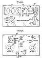
- Figure 2 is a front elevational view of the front panel of the preferred pressure monitoring system of Figure 1;
- Figure 3 is a rear elevational view illustrating the rear panel of the preferred pressure monitoring system of Figure 1;
- Figure 4 is a schematic diagram illustrating the major fluidic components of the present monitoring system as packaged inside the housing;
- Figure 5 is an enlarged cross-sectional view taken along line 5-5 of Figure 1 illustrating the pressure sensing device in the closed position;
- Figure 6 is an enlarged cross-sectional view similar to the view of Figure 5, but with the switch in the open position;
- Figure 7 is a plot of recorded output of the digital display meter illustrating the detected readings in pressure units as a function of time;
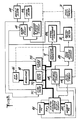
- Figure 8 is a block diagram schematically illustrating the functioning of the preferred pressure monitoring system; and
- Figure 9 is an electrical circuit diagram illustrating the preferred components of one working embodiment of the present invention.
- While this invention is satisfied by embodiments in many different forms there is shown in the drawings and will herein be described in detail a preferred embodiment of the invention, with the understanding that the present disclosure is to be considered as exemplary of the principles of the invention and is not intended to limit the invention to the embodiment illustrated. The scope of the invention will be pointed out in the appended claims.
- Adverting to the drawings, particularly to Figure 1, there is illustrated a
pressure monitoring system 20 particularly useful with electrofluidic devices for sensing pressure. One suchpressure sensing device 22 is shown connected to pressure monitor 20 by means offlexible tubing 24 which extends betweenpressure device 22 and an appropriate connection site on the rear panel of the pressure monitor as hereinafter described. The pressure monitoring system is essentially enclosed in ahousing 25, preferably made from a lightweight material such as molded high-impact plastic.Housing 25 is compact and box-shaped, and includes ahandle 26 which may be rotated around pivot pins 28 on the lateral sides of the housing to be used as a front stand or as a handle for carrying the system. The controls and main features of this pressure monitoring system are found on afront panel 29 and arear panel 30. - Turning now to Figure 2 in conjunction with Figure 1,
front panel 29 is illustrated in greater detail.Main control switch 31 includes at least five positions for the particular device being described: "OFF," "STBY," "MONITOR," "ZERO," and "SPAN." In the "OFF,' position, all functions of the system are inoperative. In "STBY," power is supplied to the solid state transducer inside the housing for warmup. Approximately five minutes of operation are allowed in this "STBY" mode to stabilize the output of the transducer and to minimize drift of the digital signal in the system. The "MONITOR" position is used after the "STBY" position, and it is in this position that the system is ready for full automatic operation. "MONITOR" is used in conjunction with one pressure sensing device at a time. When this position has been selected, the pressure supply pump inside the housing will immediately operate and thedigital display 32 will light, indicating the bias voltage on the solid state transducer. At this time, the reading should be 00.0. If not,digital display meter 32 is adjusted by turning main control switch to "ZERO." In this position, the transducer is opened to amosphere so that a zero reading adjustment can be performed. The "SPAN" position is provided to provide a full scale reading ofdigital display 32; for instance, the scale in millimeters of mercury (mm/Hg) is generally 0 to 100.0. If the gain of the digital display has changed, the display can be adjusted so that the reading is 100.0 with the system set on "SPAN" position. -
Digital display meter 32 is designed to display a numerical reading of pressure supplied by the pressure monitoring system to pressuresensing device 22. In this embodiment, the reading ondisplay meter 32 is a numerical voltage substantially equivalent to the detected pressure level of the fluid supplied to the inside of thepressure sensing device 22. A scale range switch 34, essentially a two position toggle switch, is utilized to permit the meter to display voltages in two different scale ranges; either centimeters of water or millimeters of mercury. Ascale light indicator 35 is provided to indicate that the readings are in centimeters of water, while a scalelight indicator 36 informs the operator that the display readings are in millimeters of mercury. When the scale range of the digital meter is set in the millimeters of mercury position, the scale is approximately 100.0, whereas in the centimeters of water position, the digital display reads about 135.7, these values being derived from the internal calibration of this system. Two operation indicator lights are provided, aninflation indicator 38 which indicates that fluid from the pressure monitor is being supplied to the sensing device since the switch inside the sensing device is closed; adeflation indicator light 39 is provided to indicate that the contact switch inside the pressure sensing device is open and that the mode of operation is in deflation. A digital pressure alarm set 40 is provided so that the maximum pressure level for supplied fluid to the pressure sensing device may be pre-selected. Generally speaking, the surgeon or other operator familiar with the procedure at hand, either by experience or having data available from previous testing, digitally sets the alarm level to a value which indicates that a maximum safe pressure level has been reached. Pressure alarm set 40 includes a two position adjustable digital potentiometer 41 and 42 which provides a range for the various values to be set. This potentiometer is calibrated on the same scale to correspond to whichever scale is selected fordigital display meter 32. When the internal pressure generated by the pressure monitoring system and supplied to the pressure sensing device exceeds the set alarm pressure, analarm indicator 44 lights on the front panel. This alarm light serves as a safety precaution and informs the operator that the internally generated pressure (balancing the applied external pressure to the pressure sensing device) has exceeded the pre-selected alarm level. - A sensing
device selection switch 45 includes three positions thereon, namely one, two and "AUTO." On positions one or two, only one pressure sensing device will be monitored corresponding to the position selected. However, in the "AUTO" position, two pressure sensing devices will be monitored and controlled sequentially. In operation in the "AUTO" position, the pressure monitoring system will operate only with respect to, for example, the first pressure sensing device whereupon sensing device operation light 46 will be on. After scanning this pressure sensing device for approximately 20 seconds, the pressure monitor sequentially turns to the next pressure sensing device and starts monitoring and controlling it for about the same period of time, whereupon sensingdevice operation light 48 is lit. These lights inform the operator which of the pressure sensing devices is being monitored. Thus, in the "AUTO" selection position, the monitoring system alternately monitors and controls two pressure sensing devices. It can be appreciated that the system can be designed to control many more than two devices, with the same sequential operation in mind. For practical purposes, the present invention is concerned only with a two position device with the automatic feature included. Accordingly, the cyclic operation is merely an alternating operation since only two pressure sensing devices are being monitored. - Turning now to Figure 3 wherein
rear panel 30 of the pressure monitoring system is illustrated, it can be seen that there is a provision for making a connection for two pressure sensing devices. These provisions are generallyfemale sockets 50 which are designated to provide an electrofluidic connection; i.e. it is through this connection that both an electrical connection and a fluidic connection, such as for air or other fluids, is provided. Various types of electrofluidic connectors may be employed, preferably with a female socket mounted directly inrear panel 30 of the pressure monitoring system; one typical electrofluidic junction is described in United States Patent No. 3,649,948. On this rear panel is a zeroadjustment 51 which is used in conjunction with the "ZERO" position on the main control switch on the front panel. If the digital display meter does not read zero when the main control switch is in that position, a zerocontrol potentiometer 51 is provided to make the proper adjustment; a clockwise turn will increase the reading, whereas a counterclockwise turn will decrease the reading until proper balance is achieved. Along the same lines, a spangain control potentiometer 52 is provided for use in conjunction with the "SPAN" position on the main control switch. For example, on the millimeters of mercury scale, the span reading should read 100.0; if not, the spangain control potentiometer 52 may be adjusted to provide the correct reading. A turntable,adjustable control screw 53 is provided to allow variations in the rate fluid supplied to the sensing device; slower or faster rates may be desirable depending upon the specific application of the sensing device. Analarm reset button 54 is associated with the alarm indicator light 44 on the front panel and also in conjunction with the maximumpressure alarm level 40 set by the operator beforehand. When alarm light 44 is activated due to the excessive pressure levels generated inside the pressure sensing device, the supplied fluid to the sensing device is vented to atmosphere as a safety precaution. When this occurs, the system will not operate untilalarm reset button 54 is depressed. At this time, alarm indicator light 44 will go off, and fluid supply to the pressure sensing device can continue. In addition to the visual indicator alarm on the front panel, a twoposition toggle switch 55 provides an optional audible indicator feature. Thus, if the operator of this system would prefer to have an audible alarm signal when the pre-selected pressure level has been reached, the switch may be turned to the "ON" position. In this embodiment being described, there will be no audible indicator unless the operator elects to place this switch in the "ON" position.Reset button 54 will control both visual and audible indicator alarms so that, once they are activated, depression of the reset button will turn both of them off and allow the system to once again become operational. - Two phone-type jacks are provided one to make an attachment for a
recorder output 56, the other for anevent output 58.Recorder output 56 is designed to provide a direct output signal corresponding to the voltage reading of the display meter so that the monitored pressure levels can be plotted as a function of time.Event output 58 is designed to provide a DC signal each time the electrodes make or break contact so that the inflate/deflate mode can be ascertained. Afuse 59 is provided for safety purposes while a detachable hospital grade AC cord and plug 60 is provided to make the proper connection to energize the system. - In Figure 4, the major internal fluidic components of this pressure monitoring system are schematically diagrammed so that the correlation between these components, the control features on the front and rear panels, and the functioning of the pressure monitoring system previously described can be understood. An
air pump 65 is mounted within the housing for the purpose of supplying air to the electrofluidic pressure sensing device connected to the monitoring system. This pump is preferably electrically operated, and in conjunction with the electrical switching circuit (as hereinafter more fully described) is designed to supply the air controllably to the pressure sensing device only when the pressure inside the sensing device is less than the external pressure applied to the sensing device, such as during the monitoring of intracranial pressure levels. Most of the control circuitry is found on a printedcircuit card 66, shown in phantom lines in Figure 4. Anair valve regulator 68 is connected toair pump 65 throughtubing 69 and serves to control the rate of air flow from the pump into the inside of the pressure sensing device. For example, with the pump operating, air is regulated to flow into the sensing device throughvariable flow restrictor 73 so that the rate of air flow can be controlled bycontrol screw 53 on the rear panel. With this controllable, variable restrictor the fill rate may be varied, for example, from 4 mm/Hg per second to 16 mm/Hg per second, or other rates as desirable and compatible with the flow restrictor. In addition,air regulator 68 is adapted to assist in stabilizing the selected air flow rate when the pump is operating and to provide the capability of venting the supplied air to atmospheric pressure level when the operation of the pump terminates during its cyclic operation. A filter 70 is provided in the tubing system so that particulate matter may be filtered out of the air being pumped into the sensing device. - From
air regulator 68, the air flow is carried to a series of foursolenoids 71 A, B, C and D which operate in conjunction with a transducer 72 (actually mounted on printed circuit card 66) for the purpose of detecting and measuring the levels of pressure being supplied from the air pump to the pressure sensing device, and then convert the measured pressured into an analog voltage signal.Pressure transducer 72 is preferably a pressure sensitive solid state transducer capable of producing an output voltage analogous to the level of pressure applied to the transducer. These transducers are well known and may be selected according to the choice of the designer in order to satisfactorily perform the functions of this pressure monitoring system.Manifold 75 is an open chamber into whichtubing 69 connects to provide interconnection for fluid flow throughsolenoids 71A, B, C and D. - On
rear panel 30 of the monitoring system, eachfemale electrofluidic socket 50 is shown connected bytubing 69 tosolenoids 71A, B, C and D. One or more electrofluidic pressure sensing device is connected tofemale sockets 50 and on into the sensing device. Air is supplied to the sensing device until a substantial balance is achieved between internally supplied pressure and externally applied pressure on the sensing device. Inasmuch as the supplied air is plumbed through the various output solenoids and the transducer, the pressure level of the supplied air can be detected by the transducer and converted into an electrical analog signal for display on the digital meter. Of course, while two female sockets are shown for the purpose of allowing two sensing devices to be monitored, it is appreciated that only one such device is controlled and monitored at one time with the fluidic elements illustrated. However, as explained above, with regard to Fig. 2, in the "AUTO" switching mode, the monitoring system is programmed to alternately scan two pressure sensing devices. - Referring now to Figures 5, 6 and 7, the general operation of the present pressure monitoring system in conjunction with an intracranial pressure sensing device will be described.
Pressure sensing device 22 generally includes a fluidinflatable housing 80 with a pair ofcontact electrodes electrical lead Flexible tubing 24 is connected tohousing 80 to provide fluid flow into the housing, and also to serve as an enclosure through which electrical leads 84 and 85 extend so that the proper connection can be made to the pressure monitoring system, preferably through an appropriate electrofluidic connector. Utilizing such a pressure sensing device, for example, as an intracranial pressure monitor, the housing is generally disc-shaped, and is implanted within the skull of a patient such as described in United States Patent No. 3,649,948. The intracranial pressure maintainselectrodes tubing 24 intohousing 80. This pressure level increase inside the housing is graphically illustrated by the recorded output of the pressure monitoring system in Figure 7. The increasing slope designated by numeral 86 at any given time indicates that the pressure level inside the housing is increasing; the preferred pressure monitoring system provides an inflation rate of approximately 8 millimeters mercury per second (12 centimeters of water per second), controlled by a pre-set throughadjustment screw 53 on the rear panel. Once the pressure of the supplied fluid insidehousing 80 is substantially equal to the applied external pressure against the intracranial device, the housing walls separate, thereby carrying with themelectrodes peak 88 of the plotted trace indicates the calibrated intracranial pressure detected at themoment electrodes peak 88, the plotted trace is illustrated in a decreasingslope 89 which indicates that the supplied fluid has been vented to atmosphere and the level of pressure inside the housing will return to atmospheric levels. The rate of return to atmospheric pressure levels inside the housing will normally be greater than the metered inflation rate of the sensor as the sensor is vented to atmosphere through the zero valve. After each such venting, and as long as external pressure is still being applied to the sensing device,electrodes peaks 88 will form a locus line indicating the maximum detected pressure level of the fluid supplied to the sensing device. The plot of Figure 7 indicates that, for example, the maximum calibrated output of the system is achieved approximately five to six times per minute. It should be pointed out when referring to Figure 7, that this recorded output is only for one pressure sensing device; if two devices were being utilized and the system was set on the "AUTO" mode, one device would be scanned for approximately twenty seconds so that maximum calibrated pressure readings would take place about two times; then, the operation would sequentially move to the next sensing device again for another twenty second scan time allotted. - While Figure 7 traces the measurement of the internally generated pressure as a function of time for recording purposes, during the operation of this system
digital display meter 32 would normally provide an instantaneous, current numerical reading of the pressure levels of supplied fluid. It can be appreciated that the numerical values will be changing rather rapidly during the increase of pressure into the housing of the sensing device. Accordingly,digital display meter 32 is designed to maintain the numerical reading at the maximum level achieved whenelectrodes - Turning now to Fig. 8, the functioning of this pressure monitoring system is illustrated in a block diagram of the functioning components. Sensor Number One 101 and sensor Number Two 102 represent the two electrofluidic pressure sensing devices which the present monitoring system is capable of monitoring, substantially as described above in conjunction with Figs. 5 and 6. When the electrodes inside the sensing device are in electrical contact, air is caused to enter either
sensor 101 orsensor 102 by way of the inflate valve 71 B and the electrofluidic select circuit 71 A. Air is applied tosensor air pump 65 and controlled byregulator 68 as described previously. During supply of air to the sensing device,pressure transducer 72 is measuring and detecting the pressure levels of the supplied air so that the detected pressure level can be converted into an electrical analog signal. When the electrodes inside a sensing device break electrical contact, the peak, hold and deflatecircuit 106 locks thedigital meter 32 at the pressure level whichpressure transducer 72 has detected at the instant the electrodes in the sensing device break contact. This represents the maximum pressure attained inside the sensing device which corresponds to the maximum applied pressure external to the sensing device. This reading is maintained on the digital meter for approximately 5 seconds. In the meantime, the peak, hold and deflatecircuit 106 opens the zerovalve 71 C thereby venting the air inside the sensing device to atmospheric levels. As the pressure inside the sensing device is reduced, the electrodes therein will again make etec- trical contact. Once contact is made, there is a three second delay before inflate valve 71 B controls the air from the air pump to supply air to theappropriate sensor - A
conditioning circuit 109 provides the zero and full scale pressure adjustments for thedigital meter 32. Zero is adjusted by setting themain control switch 31 on the front panel in the "ZERO" position, which opens zerovalve 71 C to atmosphere. The full-scale air span is adjusted by placingmain control switch 31 into the "SPAN" position. Air is regulated to the full scale reading of the digital display meter, for example, 100 millimeters of mercury, precisely by theair regulator 68 and then is supplied to the span valve 71 D or the inflate valve 71 B, depending on whether the main control switch is on the "SPAN" or "MONITOR" position, respectively. This full scale regulation serves as an internal reference providing a self-contained feature for full calibration of the monitoring system. - An alarm set circuit 111 compares the pressure set on the front panel by way of the two position digital potentiometer 41 and 42 with the pressure being displayed on
digital meter 32. When the displayed pressure, determined by way ofpressure transducer 72, exceeds the preset point on the front panel, alarm set circuit 111 will causealarm indicator 44, preferably a light-emitting diode, to light thereby providing a visual alarm on the front panel during operation. If the operator has activatedswitch 55 for the optional audible indicator feature on the rear panel, alarm circuit 111 will also cause anaudible alarm 114 in the form of a 1,000 hertz tone. A recorder andevent output circuit 115 buffers the pressure signal for connection to an external chart recorder, the connection being made through phono-jacks - Auto select circuit 105 is provided in conjunction with
selection switch 45 on the front panel to select the monitoring of eithersensor 101,sensor 102 or the automatic scan mode for sequentially and alternately monitoring both pressure sensing devices. A patient isolation circuit 118 isolates the patient from electrical ground for purposes of safety. - In Figure 9, the electrical circuit diagram illustrates the preferred combination of components to provide the capabilities and functions as described above with reference to Figure 8. Most of the components illustrated in Figure 9 are located on'the printed circuit board described in conjunction with Figure 4.
Switch 31A, 31 B, 31 C and 31 D denote the multi-position control switch 31 on the front panel of the monitoring system. Line voltage enters throughtransformer 122 where it is reduced to 18 volts AC. Thefull wave rectifier 124 and thevoltage regulators state pressure transducer 72 may be a stock component such as National Semiconductor part No. LX1601 G, and is powered from one leg of the +15 volt power supply. - This transducer is plumbed through
various output solenoids pressure sensing devices amplifier 132. The zero adjust 51 works in conjunction withamplifier 132, providing the user with a method of nulling the zero offset. From here the signal is fed into amplifier 134. The output of this amplifier 134 is scaled by thespan control 52, providing the user with a method of calibrating the devices span range. The output of amplifier 134 is modified by switch 34 to provide a second calibrated measuring unit. With switch 34 in position shown,section 34A provides a signal to turn onlight emitting diode 35 indicating the unit is calibrated for measuring centimeters of water. With switch inother position 34A provides a signal to light emittingdiode 36, indicating the unit is calibrated for measuring millimeters of mercury. Also in thisposition section 34B modifies the output of amplifier 134 by the resistive divider accomplished by 135, 136. These zero, span and measuring unit features are represented bysignal conditioning circuit 109 of Fig. 8. - The output of second stage amplifier 134 is fed into pin No. 5 on the
digital panel meter 32, which is located on the front panel of the monitoring system. This digital meter may be a standard item such as is presently available from Fairchild Instruments, part No. D.P.M. 300550. The adjusted amplified signal is displayed in millivolts equivalent to either millimeters of mercury or centimeters of water. The analog output signal is simultaneously fed into alarm set circuit 111 where a digital value of the millivolt signal can be set as a high limit for the system pressure. The millivolt signal arrives at the positive input ofcomparator 149. At this point, its value is compared to the value of the high alarm setting 40 located on front panel. If this millivolt signal exceeds the setting's value, the comparator will go positive setting silicone controlledrectifier 151 and thereby locking ontransistor 150 due to the gate voltage of 151.Transistor 150 will turn onvisual alarm 44 andaudible alarm 114 warning the user of the high pressure condition. The S.C.R. 151 will open the zerovalve 71 C venting the sensor pressure as a safety precaution. When switch 31 D is set in the span position,diode 144 causes a low voltage atpoint 300 in the circuit of Figure 9. Point A abovediode 144 is physically connected by an electrically conductive wire to point A' shown belowaudible alarm 114 putting a low voltage on the base/emitter circuit oftransistor 150. - Switch 55 (the
toggle switch 55 on the rear panel) is provided to include anaudible alarm 114 when the switch is closed and when the high pre-level is exceeded. Alarm reset 54 allows the audible alarm to be turned off once the system is tripped by the high signal, and also to reset the system for operation and control of the pressure monitoring devices. - The automatic scanning features of the present system are controlled by means of the
integrated circuit device 141, in conjunction withswitches 31 D and 45. This integrated circuit is available from Signetics Corporation, part No. NE555V, and performs the function indicated by manual/auto sensor select circuit 105 of Fig. - 8. The peak hold function is accomplished by the
circuit including transistor 152,capacitor 153, andresistor 154. The digital meter will hold its reading whenever the sensor contacts are open. When the sensor contactsclose transistor 152 shuts off. However, the circuit creates a time lag, giving the impression the contacts are still open. This lag is approximately 5 seconds. Switch 31 D controls the various positions provided to themain control switch 31 on the front panel and is represented by modeselect switch 31 in Fig. 8.Solenoids 71 B, 71 C, 71 D are provided to control the pressure flow in the MONITOR, ZERO and SPAN positions, respectively as selected by way of themain control switch 31. In the "AUTO" position switch 45 on the front panel is closed so that the alternating sequence for monitoring the two pressure sensing devices can become operational.Solenoid 71 A is provided for this function, andlight emitting diodes diodes - The
event output circuit 115 receives a signal during the "MONITOR" mode of operation when switch 31 D is closed across the "MONITOR" pole through transistor 145.- In conjunction withphonojack 58 on the rear panel, this circuit is designed to provide a DC signal each time the electrodes inside one of the pressure sensing devices make or break contact. The approximate output level for such signal is 1.5 volts DC. On the other hand, therecorder output 115 is associated with both alarm set circuit 111 anddigital panel meter 32 since the recorder output provides a direct output of the pressure in millivolts. The patient isolation circuit for isolating the patient from ground includes anoptical coupler 146 and a low leakage transformer 148 and a relay RLJ with its associated contacts RCJ. - With regard to Fig. 9, only the major components in the electrical circuit have been described since many minor components serve to complement the aforementioned major components and are within the purview of one normally skilled in the art to select.
- Thus, a pressure monitoring system for use with electrofluidic devices for sensing pressure is provided which automatically detects and displays the amount of pressure being externally applied to the sensing device. This monitoring system includes a high pressure alarm indicator to become activated when a pre-set level of pressure has been exceeded by the applied pressure to the sensing device.
Claims (11)
Priority Applications (1)
| Application Number | Priority Date | Filing Date | Title |
|---|---|---|---|
| AT80301235T ATE6579T1 (en) | 1979-04-20 | 1980-04-17 | PRESSURE MONITORING SYSTEM FOR ELECTROFLUIDIC MEASURING DEVICES. |
Applications Claiming Priority (2)
| Application Number | Priority Date | Filing Date | Title |
|---|---|---|---|
| US31705 | 1979-04-20 | ||
| US06/031,705 US4312361A (en) | 1979-04-20 | 1979-04-20 | Pressure monitoring system for electrofluidic sensing devices |
Publications (2)
| Publication Number | Publication Date |
|---|---|
| EP0018207A1 EP0018207A1 (en) | 1980-10-29 |
| EP0018207B1 true EP0018207B1 (en) | 1984-03-14 |
Family
ID=21860962
Family Applications (1)
| Application Number | Title | Priority Date | Filing Date |
|---|---|---|---|
| EP80301235A Expired EP0018207B1 (en) | 1979-04-20 | 1980-04-17 | Pressure monitoring system for electrofluidic sensing devices |
Country Status (6)
| Country | Link |
|---|---|
| US (1) | US4312361A (en) |
| EP (1) | EP0018207B1 (en) |
| JP (1) | JPS55158526A (en) |
| AT (1) | ATE6579T1 (en) |
| CA (1) | CA1158336A (en) |
| DE (1) | DE3066917D1 (en) |
Cited By (2)
| Publication number | Priority date | Publication date | Assignee | Title |
|---|---|---|---|---|
| US9668663B2 (en) | 2014-03-24 | 2017-06-06 | Arkis Biosciences | Implantable dual sensor bio-pressure transponder and method of calibration |
| US10244954B2 (en) | 2013-10-28 | 2019-04-02 | Arkis Biosciences Inc. | Implantable bio-pressure transponder |
Families Citing this family (40)
| Publication number | Priority date | Publication date | Assignee | Title |
|---|---|---|---|---|
| JPS57145639A (en) * | 1981-03-04 | 1982-09-08 | Teikoku Hormone Mfg Co Ltd | Body pressure meter |
| US4432372A (en) * | 1981-08-28 | 1984-02-21 | Medtronic, Inc. | Two-lead power/signal multiplexed transducer |
| US4446747A (en) * | 1982-03-11 | 1984-05-08 | Kamm Roger D | Method and apparatus for testing lip pressure applied to a smoking article and for calibrating the pressure testing apparatus |
| US4541439A (en) * | 1982-04-23 | 1985-09-17 | American Home Products Corporation (Del.) | Monitoring of capillary blood flow |
| JPS6072530A (en) * | 1983-09-28 | 1985-04-24 | 住友ベークライト株式会社 | Amplifier for pressure sensor |
| US4711248A (en) * | 1983-12-01 | 1987-12-08 | Biokinetics, Inc. | Physiological pressure monitor |
| FR2579092B1 (en) * | 1985-03-22 | 1989-06-16 | Univ Toulouse | IMPLANTABLE INTRACRANIAL PRESSURE SENSOR |
| US4672974A (en) * | 1985-06-14 | 1987-06-16 | Lee Arnold St J | Method and apparatus for "zeroing" and calibrating a catheter-tip gauge-pressure transducer |
| US4677985A (en) * | 1985-08-12 | 1987-07-07 | Bro William J | Apparatus and method for determining intracranial pressure and local cerebral blood flow |
| JPH0334162Y2 (en) * | 1985-11-11 | 1991-07-19 | ||
| US4858620A (en) * | 1986-02-28 | 1989-08-22 | Walgen Corporation | Warning system for excessive orthopedic pressures |
| IE59833B1 (en) * | 1987-03-31 | 1994-04-06 | Coralsun Enterprises Limited | Pressure measuring and recording apparatus |
| US4995401A (en) * | 1988-02-26 | 1991-02-26 | Board Of Regents, The University Of Texas System | Device for measuring anterior fontanelle pressure |
| USD333519S (en) | 1990-12-10 | 1993-02-23 | Todd Scheer | Manometer for measuring intrathoracic pressure of an infant |
| JPH10248815A (en) * | 1997-01-13 | 1998-09-22 | Suugan Kk | Probe for measuring epidural pressure and elasticity of brain parenchyma |
| US5919144A (en) * | 1997-05-06 | 1999-07-06 | Active Signal Technologies, Inc. | Apparatus and method for measurement of intracranial pressure with lower frequencies of acoustic signal |
| US6771172B1 (en) * | 1999-11-11 | 2004-08-03 | General Electric Company | Portable patient monitor with alarm light integrated into handle |
| WO2002103313A1 (en) * | 2001-06-19 | 2002-12-27 | Harada Corporation | Contact pressure measuring device for human body |
| AU2002359576A1 (en) | 2001-12-03 | 2003-06-17 | Ekos Corporation | Catheter with multiple ultrasound radiating members |
| US8062224B2 (en) | 2004-10-28 | 2011-11-22 | Uab Vittamed | Method and apparatus for non-invasive continuous monitoring of cerebrovascular autoregulation state |
| US10182833B2 (en) | 2007-01-08 | 2019-01-22 | Ekos Corporation | Power parameters for ultrasonic catheter |
| WO2009002881A1 (en) | 2007-06-22 | 2008-12-31 | Ekos Corporation | Method and apparatus for treatment of intracranial hemorrhages |
| US7938780B2 (en) * | 2008-01-31 | 2011-05-10 | Uab Vittamed Technologijos | Ultrasonic method and apparatus for measuring intracranial contents volume change |
| US8313442B2 (en) | 2009-10-21 | 2012-11-20 | Codman & Shurtleff, Inc. | Cerebral compliance monitoring |
| US20110131588A1 (en) * | 2009-12-01 | 2011-06-02 | International Business Machines Corporation | Software architecture that can sense and respond to contextual and state information |
| USD819807S1 (en) | 2014-09-22 | 2018-06-05 | Ekos Corporation | Medical device interface connector |
| USD797918S1 (en) * | 2014-09-22 | 2017-09-19 | Ekos Corporation | Medical device control unit |
| USD794662S1 (en) | 2014-09-22 | 2017-08-15 | Ekos Corporation | Medical device control unit display screen with graphical user interface |
| USD758590S1 (en) * | 2014-11-26 | 2016-06-07 | Baylis Medical Company Inc. | Switch box |
| EP3307388B1 (en) | 2015-06-10 | 2022-06-22 | Ekos Corporation | Ultrasound catheter |
| CN108267261B (en) * | 2016-12-30 | 2019-12-13 | 北京金风科创风电设备有限公司 | Electrical connections, fluid state testing devices, and fluid heat exchange systems |
| US11458328B2 (en) | 2018-10-22 | 2022-10-04 | Joovv, Inc. | Photobiomodulation therapy device accessories |
| US10478635B1 (en) | 2018-10-22 | 2019-11-19 | Joovv, Inc. | Photobiomodulation therapy systems and methods |
| USD1004789S1 (en) | 2020-09-21 | 2023-11-14 | Joovv, Inc. | Photobiomodulation therapy device |
| USD963873S1 (en) | 2020-09-21 | 2022-09-13 | Joovv, Inc. | Floor stand for a photobiomodulation therapy device |
| USD1047162S1 (en) | 2020-09-21 | 2024-10-15 | Joovv, Inc. | Photobiomodulation therapy device |
| CN113432512B (en) * | 2021-06-24 | 2024-05-07 | 合肥海天电子科技有限公司 | Detection device for direct reading and displaying of symmetry degree of waveguide port |
| CA210962S (en) * | 2021-10-29 | 2023-12-13 | Classys Inc | High frequency therapy device |
| CN115508004B (en) * | 2022-10-26 | 2025-06-20 | 河北省计量监督检测研究院廊坊分院 | Small intracranial pressure monitor pressure detection device |
| CN118873834B (en) * | 2024-07-09 | 2025-02-07 | 中国人民解放军总医院第二医学中心 | Shaping floating heart temporary pacing electrode |
Family Cites Families (12)
| Publication number | Priority date | Publication date | Assignee | Title |
|---|---|---|---|---|
| US3104661A (en) * | 1959-12-14 | 1963-09-24 | Beckman Instruments Inc | System for continuous blood pressure determination |
| US3452744A (en) * | 1964-11-03 | 1969-07-01 | Air Shields | Blood pressure monitoring apparatus |
| US3636941A (en) * | 1970-01-12 | 1972-01-25 | Hoffmann La Roche | Sphygmomanometer alarm reset technique |
| US3649948A (en) * | 1970-04-23 | 1972-03-14 | Ladd Res Ind | Electric-pneumatic junction |
| DE2035453C3 (en) * | 1970-07-17 | 1974-08-08 | Siemens Ag, 1000 Berlin Und 8000 Muenchen | Device for recording tokograms |
| US3686958A (en) * | 1971-02-22 | 1972-08-29 | Ladd Res Ind | Fiber optic pressure detector |
| US3744490A (en) * | 1971-11-16 | 1973-07-10 | H Fernandez | Automatic device for recording blood pressure |
| US3789667A (en) * | 1972-02-14 | 1974-02-05 | Ladd Res Ind Inc | Fiber optic pressure detector |
| US4050452A (en) * | 1975-09-26 | 1977-09-27 | Milstein Medical Research Foundation, Inc. | Alarm actuation arrangement for an automatic blood pressure recorder |
| US4058117A (en) * | 1975-10-17 | 1977-11-15 | Palo Alto Research Associates | Blood pressure measuring apparatus |
| US4080653A (en) * | 1976-01-30 | 1978-03-21 | Barnes Jr Ralph W | Intracranial pressure data processor |
| JPS5932136B2 (en) * | 1976-08-27 | 1984-08-07 | 株式会社医療工学研究所 | Brain pressure measuring device |
-
1979
- 1979-04-20 US US06/031,705 patent/US4312361A/en not_active Expired - Lifetime
-
1980
- 1980-04-17 CA CA000350093A patent/CA1158336A/en not_active Expired
- 1980-04-17 EP EP80301235A patent/EP0018207B1/en not_active Expired
- 1980-04-17 DE DE8080301235T patent/DE3066917D1/en not_active Expired
- 1980-04-17 AT AT80301235T patent/ATE6579T1/en active
- 1980-04-18 JP JP5056180A patent/JPS55158526A/en active Pending
Cited By (3)
| Publication number | Priority date | Publication date | Assignee | Title |
|---|---|---|---|---|
| US10244954B2 (en) | 2013-10-28 | 2019-04-02 | Arkis Biosciences Inc. | Implantable bio-pressure transponder |
| US9668663B2 (en) | 2014-03-24 | 2017-06-06 | Arkis Biosciences | Implantable dual sensor bio-pressure transponder and method of calibration |
| US10791944B2 (en) | 2014-03-24 | 2020-10-06 | Arkis Biosciences Inc. | Implantable dual sensor bio-pressure transponder and method of calibration |
Also Published As
| Publication number | Publication date |
|---|---|
| US4312361A (en) | 1982-01-26 |
| EP0018207A1 (en) | 1980-10-29 |
| JPS55158526A (en) | 1980-12-10 |
| CA1158336A (en) | 1983-12-06 |
| DE3066917D1 (en) | 1984-04-19 |
| ATE6579T1 (en) | 1984-03-15 |
Similar Documents
| Publication | Publication Date | Title |
|---|---|---|
| US4312361A (en) | Pressure monitoring system for electrofluidic sensing devices | |
| CA1307986C (en) | Syringe pressure calibration reference | |
| US5021046A (en) | Medical pressure sensing and display system | |
| US5169235A (en) | Radiation type thermometer | |
| US4847783A (en) | Gas sensing instrument | |
| US4672974A (en) | Method and apparatus for "zeroing" and calibrating a catheter-tip gauge-pressure transducer | |
| US6120457A (en) | In vivo zeroing of catheter pressure sensor | |
| US3686958A (en) | Fiber optic pressure detector | |
| US5493100A (en) | Thermistor flow sensor and related method | |
| US3710778A (en) | Blood gas sensor amplifier and testing system | |
| US6168567B1 (en) | Hybrid sphygmomanometer | |
| US3926179A (en) | Blood pressure measuring apparatus | |
| US5792665A (en) | Oxygen sensing method and hand held analyzer therefore | |
| US4103678A (en) | Nocturnal penile tumescense monitor | |
| US4054783A (en) | Decompression plan device | |
| EP0970656B1 (en) | Hybrid sphygmomanometer | |
| US3593704A (en) | Pulse sensor for body pulse rate measuring means | |
| US8121676B2 (en) | System for measuring and indicating changes in the resistance of a living body | |
| US5264833A (en) | Automatic leak detector | |
| US3851528A (en) | Electronic thermometer | |
| US5089961A (en) | Apparatus and method for vascular examination of a limb | |
| US5065611A (en) | System for calibrating the span of pressure measuring instruments | |
| JPH0351410B2 (en) | ||
| EP0634185A2 (en) | Digital dual pressure guage | |
| GB2199953A (en) | Measurement of pressure at an interface |
Legal Events
| Date | Code | Title | Description |
|---|---|---|---|
| PUAI | Public reference made under article 153(3) epc to a published international application that has entered the european phase |
Free format text: ORIGINAL CODE: 0009012 |
|
| AK | Designated contracting states |
Designated state(s): AT BE CH DE FR GB LU SE |
|
| 17P | Request for examination filed |
Effective date: 19810406 |
|
| GRAA | (expected) grant |
Free format text: ORIGINAL CODE: 0009210 |
|
| AK | Designated contracting states |
Designated state(s): AT BE CH DE FR GB LI LU SE |
|
| REF | Corresponds to: |
Ref document number: 6579 Country of ref document: AT Date of ref document: 19840315 Kind code of ref document: T |
|
| REF | Corresponds to: |
Ref document number: 3066917 Country of ref document: DE Date of ref document: 19840419 |
|
| ET | Fr: translation filed | ||
| PG25 | Lapsed in a contracting state [announced via postgrant information from national office to epo] |
Ref country code: LU Free format text: LAPSE BECAUSE OF NON-PAYMENT OF DUE FEES Effective date: 19840430 |
|
| PLBE | No opposition filed within time limit |
Free format text: ORIGINAL CODE: 0009261 |
|
| STAA | Information on the status of an ep patent application or granted ep patent |
Free format text: STATUS: NO OPPOSITION FILED WITHIN TIME LIMIT |
|
| 26N | No opposition filed | ||
| PGFP | Annual fee paid to national office [announced via postgrant information from national office to epo] |
Ref country code: SE Payment date: 19890410 Year of fee payment: 10 |
|
| PGFP | Annual fee paid to national office [announced via postgrant information from national office to epo] |
Ref country code: FR Payment date: 19890412 Year of fee payment: 10 Ref country code: AT Payment date: 19890412 Year of fee payment: 10 |
|
| PGFP | Annual fee paid to national office [announced via postgrant information from national office to epo] |
Ref country code: LU Payment date: 19890428 Year of fee payment: 10 Ref country code: BE Payment date: 19890428 Year of fee payment: 10 |
|
| PGFP | Annual fee paid to national office [announced via postgrant information from national office to epo] |
Ref country code: GB Payment date: 19890430 Year of fee payment: 10 |
|
| PGFP | Annual fee paid to national office [announced via postgrant information from national office to epo] |
Ref country code: CH Payment date: 19890523 Year of fee payment: 10 |
|
| PGFP | Annual fee paid to national office [announced via postgrant information from national office to epo] |
Ref country code: DE Payment date: 19890630 Year of fee payment: 10 |
|
| PG25 | Lapsed in a contracting state [announced via postgrant information from national office to epo] |
Ref country code: GB Effective date: 19900417 Ref country code: AT Effective date: 19900417 |
|
| PG25 | Lapsed in a contracting state [announced via postgrant information from national office to epo] |
Ref country code: SE Effective date: 19900418 |
|
| PG25 | Lapsed in a contracting state [announced via postgrant information from national office to epo] |
Ref country code: LI Effective date: 19900430 Ref country code: CH Effective date: 19900430 Ref country code: BE Effective date: 19900430 |
|
| BERE | Be: lapsed |
Owner name: CODMAN & SHURTLEFF INC. Effective date: 19900430 |
|
| GBPC | Gb: european patent ceased through non-payment of renewal fee | ||
| PG25 | Lapsed in a contracting state [announced via postgrant information from national office to epo] |
Ref country code: FR Effective date: 19901228 |
|
| REG | Reference to a national code |
Ref country code: CH Ref legal event code: PL |
|
| PG25 | Lapsed in a contracting state [announced via postgrant information from national office to epo] |
Ref country code: DE Effective date: 19910101 |
|
| REG | Reference to a national code |
Ref country code: FR Ref legal event code: ST |
|
| EUG | Se: european patent has lapsed |
Ref document number: 80301235.0 Effective date: 19910110 |