EP0016427B1 - Multi-channel digital speech synthesizer - Google Patents
Multi-channel digital speech synthesizer Download PDFInfo
- Publication number
- EP0016427B1 EP0016427B1 EP80101328A EP80101328A EP0016427B1 EP 0016427 B1 EP0016427 B1 EP 0016427B1 EP 80101328 A EP80101328 A EP 80101328A EP 80101328 A EP80101328 A EP 80101328A EP 0016427 B1 EP0016427 B1 EP 0016427B1
- Authority
- EP
- European Patent Office
- Prior art keywords
- parameters
- sound
- filter
- synthesizer
- sample
- Prior art date
- Legal status (The legal status is an assumption and is not a legal conclusion. Google has not performed a legal analysis and makes no representation as to the accuracy of the status listed.)
- Expired
Links
Images


Classifications
-
- G—PHYSICS
- G10—MUSICAL INSTRUMENTS; ACOUSTICS
- G10L—SPEECH ANALYSIS TECHNIQUES OR SPEECH SYNTHESIS; SPEECH RECOGNITION; SPEECH OR VOICE PROCESSING TECHNIQUES; SPEECH OR AUDIO CODING OR DECODING
- G10L25/00—Speech or voice analysis techniques not restricted to a single one of groups G10L15/00 - G10L21/00
-
- G—PHYSICS
- G10—MUSICAL INSTRUMENTS; ACOUSTICS
- G10L—SPEECH ANALYSIS TECHNIQUES OR SPEECH SYNTHESIS; SPEECH RECOGNITION; SPEECH OR VOICE PROCESSING TECHNIQUES; SPEECH OR AUDIO CODING OR DECODING
- G10L19/00—Speech or audio signals analysis-synthesis techniques for redundancy reduction, e.g. in vocoders; Coding or decoding of speech or audio signals, using source filter models or psychoacoustic analysis
Definitions
- the present invention relates to artificial- speech production devices, and more particularly it concerns a digital synthesizer capable of operating in time division over a plurality of channels, that is of serving simultaneously a plurality of users.
- Human-speech synthesis is an aspect of the general problem of the research for simple means that can be used by unskilled people in man-machine communication.
- the interest raised by solutions based on speech, that is the most natural means of communication for man, is evident.
- human-speech synthesis permits the development and realization of services that at present are not available or are very expensive, because they require full-time employment of human operators or expensive terminals at the subscriber's premises. Examples are automatic provision of information from data bases, text reading machines for the blind as well as telephone services.
- a synthesis system makes use of data concerning entire sentences, or words or portions of words, stored in coded form; the presence of a decoder or synthesizer is then necessary in order to reconstruct the signal in a suitable form for a human listener.
- coding techniques may be used based on mathematical models simulating the speech generation.
- the natural speech-generating system is schematized by a generator of an excitation function and a time- varying filtering system consisting of the resonant cavities of an acoustic tube with stiff walls and variable cross section.
- the excitation function may be a sequence of periodic or pseudo- random pulses, dependent on whether the sound is voiced or unvoiced.
- the filter coefficients which represent the reflection coefficients between the different cavities of the acoustic tube and are continuous functions of time, can be considered constant during short time intervals, of-the order of 10 ms, as within intervals of this duration the acoustic tube does not undergo variations substantially affecting the sound nature.
- the filter will present a variable gain corresponding to the sound intensity.
- These parameters are obtained from natural speech by analysis techniques dependent on the chosen speech generation model and are stored e.g. into a computer memory.
- Single channel synthesizers generally comprising the element stated in the prior art portion of claim 1 are already known (pages 109-116 of Electronics International, Vol 51, No. 18 of the 31 st August, 1978). These known synthesizers are disadvantageous in that they make the synthesis filter coefficients vary at constant time intevals, so that they can hardly supply a certain degree of naturalness to the synthesized signal.
- a synthesizer based on the above speech generation scheme, wherein the synthesis filter receives the various sets of parameters at variable intervals, so as to better reproduce the 'vocal-tract variations, and wherein the updating of filter coefficients takes place only at the beginning of the oscillation period of the voiced sound, giving a good continuity of the synthesized sound; in addition the proposed synthesizer can simultaneously serve a plurality of channels, that is it can emit a plurality of vocal messages at a time.
- a speech synthesizer comprising a lattice filter simulating the vocal tract and generating voice samples by processing samples of waveforms of periodic or random excitation, supplied by respective generators, dependent on whether the vocal-tract configuration concerns a voiced or unvoiced sound, said processing occurring on the basis of coefficients supplied by an external unit that stores sets of parameters which charac-, terize elements permitting the build-up of a dictionary that can be synthesized, and comprise, besides said coefficients, the information on the voiced or unvoiced nature of the sound, the pitch period in case of periodic excitation, and the intensity of the sound to be synthesized, is characterized in that it is a multichannel digital speech synthesizer, and said generators and filter are connected with said external unit which also stores parameters characterizing the durations of the validity intervals of the different sets of parameters, through a plurality of input modules, whose number is the same as that of the synthesizer channels, and a control unit acting as an interface towards the external unit;
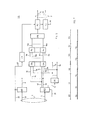
- the synthesizer As shown in Fig. 1, the synthesizer according to the invention, denoted by SIN, comprises a control unit UC, a plurality of input modules INa, lNb ... INn (as many as the channels that can be handled at a time), an excitation generator GE, a filter TV acting as the so-called vocal-tract, and an output module MU emitting the synthesized sound.
- the synthesizer is connected with an external unit UE whose tasks will be specified hereinafter.
- Control unit UC is an interface towards external unit UE. It must transfer to the subsequent devices of the synthesizer the parameters characterizing the sound to be emitted and signals for selecting the interested channel; in addition it is to store and transfer to external unit UE the requests for new parameters arriving from the various channels.
- the structure of UC will be described in more detail with reference to Fig. 2.
- External unit UE generally consisting of a processing system, stores the parameters characterizing all the elements utilized to build up a vocabulary (e.g. the so called diphones) and choses every time those corresponding to the words to be pronounced.
- a vocabulary e.g. the so called diphones
- the messages comprise, besides the parameters, a control word identifying the channel (that is the input module lNa ... INn) which the message is intended for; the control word associated with the first or the last set of parameters sent to a channel contains also the "start” or respectively the "stop” for the channel operation.
- Each message may comprise for instance 13 words relating to the parameters (10 filter coefficients, pitch period T, duration D of parameter validity, filter gain G) preceded by the control word.
- the mode of operation UE depends on the synthesizer application.
- An example referring to the use of the synthesizer in an automatic text-to-speech synthesis for Italian language, has been described by P. M.,Bertinetto, C. Miotti, S Sandri, E. Vivalda in the paper "An interactive synthesis system for detection of Italian prosodic rules':': CSELT Rapporti Tecnici, Vol. V, No. 5, December 1977.
- External unit UE and control unit UC are interconnected by means of: a connection 1, transferring to UC the messages with the set of parameters of the sound to synthesize and the corresponding control word; a connection 2 transferring to UC timing signals for the loading of such messages; a connection 3 transferring to UE the message request of each channel and the identity of the requesting channel; a connection 30 transferring to UC the signals acknowledging receipt of the requests by UE.
- Input modules INa, lNb ... INn control the transfer of the parameters from control unit UC (and consequently from external unit UE) to excitation generator and synthesis filter.
- Said modules also generate the parameter requests for transmission towards UE and temporarily store the parameters sent by UE, as said parameters are received at the slow speed characteristic of the transfer between UE and UC, and are emitted at the high speed requested by the generator or the filter, as better explained hereinafter.
- input modules INa ... INn are connected with control unit UC through a bus 4 transferring the parameters to said modules; connections 5a ... 5n on which a select signal for the module interested in a synthesis operation is present; and connections 6a ... 6n carrying to UC the transfer request for new parameters.
- the structure of the input modules will become clearer from Fig. 3.
- Excitation generator GE is time division multiplexed over the n channels and comprises a periodic-excitation generator EP as well as a random-excitation generator EC, whose outputs are connected with a switch S1 connecting filter TV with generator EP or generator EC dependent on whether the sound is voiced or unvoiced.
- the control signal for switch S1 is supplied by the input modules through wires 7a ... 7n, which convey the information on the nature of the sound to be synthesized; these wires can join into a common wire 7.
- T pitch period expressed as a number of samples, e.g. at 8kHz
- the first of these characteristics allows elimination of variations in the d.c. level between successive sound elements
- the second characteristic allows the control of the intensity of the synthesized sound by the only factor G (filter gain). This is of advantage for the determination of the intonation contour.
- the information on period T is sent to EP by input modules through connections 8a, 8b ... 8n, that can join into common connection 8.
- Random excitation consists of a pseudorandom sequence of +1 or -1 of length sufficient to render periodicity unperceived, for instance a sequence of 2 10 pulses. Also in this case a signal with unitary power and substantially zero means value is obtained.
- generators EP, EC can consist of read-only-memories.
- Filter TV implementing the speech-production model described in the introductions is time-division multiplexed over the n channels and is a lattice filter having a plurality of identical cells, the filter multiplicative coefficients and gain are supplied by the input modules through connections 9a, 9b... 9n that join into a common connection 9.
- the structure of the filter is depicted in greater details in Figures 4 and 5.
- Output module MU consists of a bank of n digital-to-analog converters, which convert into analog form the signals coming from filter TV and emit the converted signals onto outputs u a , U b - -.U n .
- GE, TV and MU are controlled by signals generically denoted by references CK and TR. These signals are depicted in Fig. 6.
- One of the signals CK also controls some operations of input modules.
- RE1 denote two registers which temporarily store respectively the words relevant to the parameters (carried by wires 10 of connection 1) and the control word (carried by wires 11 of the same connection). Such registers load the signals present at their inputs upon command of respective timing signals supplied by the external unit through the sets of wires 20, 21 that together compose connection 2 of Fig. 1.
- the output of RE1 is connection 4, already described.
- the outputs of RE2 are three connections 12, 13, 14 respectively carrying the START and STOP signals and the address of the channel for which the parameters are intended.
- Connection 14 forms the input of a decoder DE, whose outputs are connections 5a ... 5n carrying the channel selection signals.
- Connections 12, 13 form two inputs of n identical logic circuits L1 1 ... L1 n. Each circuit is associated to a synthesizer channel and has a further input connected with one of connections 5a ... 5n.
- Outputs 15a ... 15n of L1 a ... L1 are connected with an input of corresponding gates Pa ... Pn, that are also associated respectively with a synthesizer channel and have a second input connected with one of connections 6a ... 6n conveying the requests for parameters.
- the set of logic circuits L1 a ... L1 n and gates Pa ... Pn acts as a network enabling the transmission of said requests towards the external unit.
- the i-th logic circuit Li enables the i-th gate Pi to load the parameter request present on the connection 6i corresponding to the selected channel.
- the gate is disabled in presence of the STOP signal on wire 14.
- Outputs 16a ... 16n of gates Pa ... Pn are connected with a coder COD that supplies at the output the address of the channel requesting the parameters.
- the output of the coder is connected with a FIFO (first in-first out) memory ME1, that is a memory organizing the addresses relevant to the request so that they are read in the order they are presented.
- the addressing of memory ME1 is advanced by one step whenever the transfer of a set of parameters to the input module is completed; for instance the timing signal present on wire 20 can operate a counter CN advancing the addressing of ME1 after the storing of the last of block of parameters.
- a second output of ME1 whose condition denotes whether the memory is empty or contains requests for transfer of parameters, is connected with a logic network L2 designed to inform UE of the presence of requests.
- the output signal of L2 is sent to UE through wires 32 of connection 3 and forms an interrupt signal.
- a further input of L2 receives from UE through connection 30 the acknowledgement receipt of the interrupt signal, that allows further possible requests to be dealt with.
- Fig. 3 shows that a generic input module INi consists of three random access memories ME2, ME3, ME4, of two presettable counters CD, CT and a switch S2.
- Memories ME2, ME3 effect a temporary storage of a set of parameters of the diphone to synthesize, coming from control unit UC (Fig. 1) through connection 4. These memories alternate in read and write operations, that is while a set of parameters is being written for instance in ME2, the parameters written in ME3 in the preceding writing phase are being read. The alternation of writing and reading in these memories is controlled by counters CD, CT, which provide also for the "read" command, as it will be explained hereinafter.
- the gain and coefficients of filter TV (Fig. 1) are sent to memory ME4 (Fig. 3) through connection 90; the bit specifying whether the sound is voiced or unvoiced is sent via wire 7i as command signal to both switch S2 and switch S1 (Fig. 1) of excitation generator GE; pitch period T is communicated through connection 8i both to a switch S2, in order to be transferred to CT, and to periodic excitation source EP (Fig. 1).
- the writing in memory ME4 is enabled by the same command enabling the reading in ME2 or ME3 of the information intended for filter TV (Fig. 1); memory ME4 is cyclically read, whenever the speech sample corresponding to the i-th channel is to be synthesized (for instance every 125 ⁇ s).
- Counter CD can count from O to value D (expressed as number of samples) supplied by memories ME2 or ME3; once such value is reached, CD presents on its output 6i a signal that is sent to control unit UC (Fig.
- Counter CT controls the reading in ME2, ME3 and the transfer to ME4 of the filter coefficients, and of the gain, of the pitch period and of the bit denoting the type of sound. It is connected by S2 with connection 8i or with output 61 of counter CD, according to whether the sound is voiced or unvoiced.
- CT receiving the information on period T (expressed as number of samples) counts from 0 to T and, as soon as value T is reached it emits on output 60 a read command.
- counter CT is set to the value attained at that moment by counter CD, and therefore it causes data transfer at the end of that interval D.
- the use of only one buffer memory could determine inadmissible overlaps of operations.
- Fig. 4 shows the functional structure of filter TV.
- Cell TV1 is connected with excitation generator GE (Fig. 1) through multiplier MT (Fig. 4) computing the product between a sample U of the excitation waveform (present on connection 40), and the wanted value of the intensity of the synthesized sound sample (filter gain, present on connection 9). The result of this product is sample EO + of direct wave.
- Cell TV10 is connected with output module MU.
- Cells TV2 ... TV10 are identical and functionally consist of a pair of multipliers M11, ML2, of a pair of adders A1, A2 and of a memory element Z- 1.
- Adder SM subtracts the output signal of multiplier ML2 from the sample direct wave Ei + supplying at the output the subsequent sample of direct wave; adder SM2 adds the value of the reflected wave Ei-, stored during the computing of the preceding sample, to the output signal of multiplier ML1, thus generating a sample of reflected wave to be utilized in computing the subsequent sample.
- Cell TV1 comprises, besides memory element Z- 1 , only adder SM and multiplier ML2.
- the circuit implementation will comprise: a single adder and a single multiplier, operating in time division to carry out the functions of each cell and each channel; a memory for the samples Ei- of all the channel, and a microprogram supplying control and timing signals.
- RE3, RE4 are two input registers for a multiplier ML3.
- RE3 loads either samples U of the excitation waveform (present on connection 40) or samples EZ of the direct wave or E2 of the reflected wave, supplied by a register RE5 or a random access memory ME5 respectively, also connected with connection 40.
- Register RE4 loads the gain or the filter coefficients, carried by connection 9.
- RE3, RE4 are timed by a clock signal CK1.
- Multiplier ML3 effects, in time division for all the filter cells and all the channels, the products between the samples of the excitation waveform and the gain and the products between the samples of direct or reflected wave and the filter coefficients.
- multiplier ML3 The output of multiplier ML3 is connected with a register RE6 which loads the most significant digits of the products effected by ML3, and transfers them either to register RE5, through connection 42, or to a logic network L3.
- the operations of RE6 are timed by a signal CK2.
- RE3, RE4, ML3, RE6 performs the functions of multipliers ML1, ML2, MT of Fig. 4.
- Logic network L3 is designed to invert the sign of the signals present at its input, or let them through unchanged, on the basis of a suitable control signal A/S; the output of L3 is connected with an input of an adder SM3 with overflow control, that has a second input connected with connection 40.
- the output of SM3 is connected with a register RE7, that upon command of a timing signal CK4 presents the result of the addition (that is a sample E + or a sample E-) on connection 42 and sends it to register RE5 or memory ME5.
- the whole of L3, SM3, RE7 performs the functions of adders SM1, SM2 of Fig. 4.
- Register RE5 timed by a signal CK3, acts as a connecting element between adjacent cells; memory ME5, in which reading and writing operations are controlled by a signal R/W, acts as memory of the internal states. Owing to the filter architecture, connection 40 performs also as output connection 41.
- a plurality of filter devices and the excitation generator have access to common connections or buses 40 (41) and 42.
- means are to be provided, e.g. "tristate" circuits, which connect each device with the bus only at the presence of a suitable enabling signal.
- TR1 ... TR6 are represented in Fig. 6, together with signals CK1 ... CK4.
- reference will be made only to “enabled” and “disabled” device, in order to denote possibility or impossibility of accessing a bus.
- timing and enabling signals are considered active (that is they allow or cause the desired operation) when they are at level 1; for the signals A/S and R/W, that according to their state allow either of two operations, it will be assumed that level 1 thereof causes respectively sign inversion of the signals coming into logic network L3 or the reading in ME5.
- Fig. 6 The diagram of Fig. 6 is merely qualitative. However, for the sake of clarity of description and by way of example, reference will be made, if necessary, to minimum durations of 100 ns, and to operations that follow one another at intervals multiple of the minimum duration.
- ⁇ will denote the most significant parts of the products effected by ML3 (Fig. 5). More particularly n1 will be the most significant part of the product of reflected wave E1 - by coefficient K1; ⁇ 2, ⁇ 3 will be the most significant parts of the products of waves E2-, E2 + by coefficient K2, and so on up to ⁇ 18, ⁇ 19 that refer to the products of E 10-, E 10 + by K 10.
- Signals outgoing from adder SM3 are values of the direct or reflected wave, as already stated, and therefore they will be denoted by the symbols of said waves.
- bus 40 is enabled to receive signals from generator GE of Fig. 1 (signal TR1 at 1) and is disconnected from RE5 and ME5 (signals TR2, TR3 at 0).
- the passage at 1 of CKa causes the transfer to registers RE3, RE4 of excitation sample U and filter gain G, which are loaded at the arrival of a pulse of CK1.
- the arrival of this pulse can be considered simultaneous with the passage to 1 of CKa.
- ML3 begins to compute the product between U and G.
- TR1 passes to 0 and TR3, TR4 pass to 1.
- memory ME5 is connected with bus 40 and can send onto it sample E1-; register RE6 is in turn connected with bus 42, and will send onto it its contents (forming sample EO + of the direct wave) at the arrival of the first pulse of signal CK2.
- the arrival of the first pulse of CK2 is simultaneous with the arrival of a new pulse of CK1, so that RE3 and RE4 will load respectively sample E1 - of the reflected wave and filter coefficient K1, and ML3 begins to effect the product thereof.
- a first pulse of CK3 arrives and causes the actual load of EO + in RE5.
- connection 40 is disconnected from ME5 and connected with RE5 (signals TR3 at 0 and TR2 at 1).
- ⁇ 1 is loaded in RE6.
- the control signal of L3 is at 1, thus the content of RE6 is inverted in sign and sent to SM3, that receives also sample EO + supplied by RE5. Then SM3 effects the difference between EO + and ⁇ 1, and the result E1 is loaded into RE7 at the arrival of the first pulse of CK4.
- RE7 can present sample E1 + on bus 42 and ME5 can present sample E2- on bus 40.
- adder SM3 can load sample E1 + and ⁇ 2, the latter being inverted in sign because A/S is at 1. After 300 ns a pulse of CK4 arrives, RE6 is disabled and RE7 is enabled. The addition effected by SM3, forming E2 + , is sent to RE5 where it is loaded at the arrival of the subsequent pulse of CK3. After 100 ns more, the next pulse of CK1 determines the loading of E2 + and K2, that are multiplied in ML3. At the same instant RE7 is disconnected from bus 42.
- the procedure is identically repeated till the last cell is to be processed.
- signal TR6 passes to 1 so that buffer ME6 is enabled to send onto bus 42 sample E10 + ; this one will be loaded in ME5 as value (E10 - )s to be used in the subsequent cycle, as soon as the new write command for ME5 arrives (e.g. after 100 ns).
- the filter is now ready to process a speech sample relevant to the subsequent channel.
- Fig. 7 shows the durations of validity (windows) D1 ... D5 for the first five sets of filter parameters, and pitch periods T for the voiced sounds. More particularly: the first and third windows D1, D3 are relevant to vocal tract configurations corresponding to voiced sounds with periods T1, T3 respectively; the second, fourth and fifth windows D2, D4, D5 (represented by a double dotted line are relevant to vocal tract configurations corresponding to unvoiced sounds.
- the drawing shows also that the first validity window D1 is preceded by a time DO allowing the loading of the first set of parameters.
- Register RE2 (Fig. 2) loads the control words when the timing signal arrives on connection 21; the address bits are sent to decoder DE, where output 5a is activated, thus enabling input module INa (Fig. 1).
- the control word comprises also the start signal, that in conjunction with the signal present on wire 5a starts logic circuit L1 a (Fig. 2).
- Said logic circuit enables gate Pa to load the parameter requests that are going to arrive from input module INa (Fig. 1) via connection 6a: in the meanwhile coder COD (Fig. 2), memory ME1 and logic network L2 are supposed to be inactive in the absence of requests from other channels.
- RE1 After the control word has been loaded, RE1, stores the words relevant to the parameters, which are transferred through connection 4 for instance to memory ME2 (Fig. 3) of module INa (Fig. 1), whose counters CD, CT (Fig. 3) are temporarily set on fixed and equal values DO, TO (Fig. 7), such as to allow the complete loading of ME2 (Fig. 3).
- counter CD sends onto connection 6a the request for the second set of parameters that through gate Pa Fig 2) is stored in ME1; once the counting of CD is over (Fig. 3), the reading in ME2 and the writing into ME3 are enabled; the simultaneous end of counting of CT enables the writing into ME4 and causes the actual reading of ME2.
- counter CD receives through connection 91 the value D1 (Fig. 7) of the duration of validity of the first set of parameters.
- the signal present on wire 7a (Fig. 1) positions S1 so as to interconnect TV and EP, and positions S2 (Fig. 3) so as to interconnect CT and ME2; the value of T1 (Fig. 7) is sent to both EP (Fig. 1) and CT (Fig. 3) through connections 8a and 8; filter gain and coefficients are stored in ME4.
- Counters CD, CT begin counting from 0 to D1 or respectively T1; during this counting, whenever the time base marks the channel time allotted to channel a, memory ME6 is read and generator EP (Fig. 1) transfers to TV a sample of periodic excitation, that is processed in TV as already described. In the case of 8 channels with a 125 ps frame, as assumed, TV is assigned about 16 ps to process the sample. At the end of the 16 ⁇ s the processed sample is supplied to MU that converts it into analog form and sends it onto output u a .
- counter CT (Fig. 3) stops counting and causes the writing in ME4 of the data of the buffer memory which is in reading phase. As the counting of CD is not yet over, memory ME2 is still being read, and thus the first set of parameters is still present on wires or sets of wires 7a, 8a, 90, 9a.
- CT begins to count again from 0 to T1, and at the filter output there are always samples processed by the first group of coefficients. During this time, every 125 Its, a voice sample is being generated by filter TV.
- a new request for parameters is sent to UC (Fig. 1) through wire 6a: this request is loaded by gate Pa (Fig. 2) that is still enabled, as the message is not ended, and processed as the preceding request.
- the parameters of the third set are transferred to IN a (Fig. 1) in the way already described.
- the end of the counting of CD (Fig. 3) has enabled the writing in ME2, that stores said parameters, and the reading in ME3.
- the "read enable" for ME3 only causes the transfer of value D2 to CD; ME4 has not received the "write enable” and thus the synthesis still occurs on the basis of the parameters of the first set.
- M3 emits the bit characterizing the kind of sound which the second set of parameters is referred to, and the filter coefficients and gain to be utilized in the second window are stored in ME4.
- the sound is unvoiced and therefore S1 (Fig. 1) and S2 (Fig. 3) are switched, so that CT is set to the value that CD has reached at that moment and TV (Fig. 1) is connected with EC. Every 125 /l s, EC will supply a random-excitation sample that is processed in TV by the values of the coefficients and of the gain stored in ME4 (Fig. 3).
- value D2 is reached by CD, the request is sent for the fourth set of parameters and the functions of ME2, ME3 interchange again:
- Counter CD begins to count from 0 to D3 and filter gain and coefficients are transferred to ME4; as window D3 is relevant to a voiced sound, having period T3, switches S1, S2 will be reset to the position corresponding to this kind of sound, so that CT begins to count from 0 to T3.
- period T3 is shorter than durations D3 of parameter validity; then, at the end of the first counting from 0 to T3 of CT (Fig. 3) and at the end of window D3 (Fig. 7), the situation already examined for the first set of parameters is repeated. More particularly:
- control word comprises the "STOP" signal that disables logic L1 a (Fig. 2) thus preventing the possible transfer to UE (Fig. 1) of message requests coming from channel a.
Landscapes
- Engineering & Computer Science (AREA)
- Computational Linguistics (AREA)
- Signal Processing (AREA)
- Health & Medical Sciences (AREA)
- Audiology, Speech & Language Pathology (AREA)
- Human Computer Interaction (AREA)
- Physics & Mathematics (AREA)
- Acoustics & Sound (AREA)
- Multimedia (AREA)
- Compression, Expansion, Code Conversion, And Decoders (AREA)
- Electrophonic Musical Instruments (AREA)
Abstract
Description
- The present invention relates to artificial- speech production devices, and more particularly it concerns a digital synthesizer capable of operating in time division over a plurality of channels, that is of serving simultaneously a plurality of users.
- Human-speech synthesis is an aspect of the general problem of the research for simple means that can be used by unskilled people in man-machine communication. The interest raised by solutions based on speech, that is the most natural means of communication for man, is evident. In addition, human-speech synthesis permits the development and realization of services that at present are not available or are very expensive, because they require full-time employment of human operators or expensive terminals at the subscriber's premises. Examples are automatic provision of information from data bases, text reading machines for the blind as well as telephone services.
- Among the latter it is worth mentioning: assistance to the subscriber with call transfer to a computer informing that the telephone number has changed, that the routing is out of order or congested, that the called subscriber is absent and can be possibly reached by dialling another number; automatic information by voice about the duration and cost of a call, etc.
- The various kinds of techniques and the complexity of the speech synthesis systems mainly depend on the kind of application.
- Neglecting the simplest cases in which the messages to be synthesized are recorded in analog form, for instance on a tape or a disk, generally a synthesis system makes use of data concerning entire sentences, or words or portions of words, stored in coded form; the presence of a decoder or synthesizer is then necessary in order to reconstruct the signal in a suitable form for a human listener.
- An Italian-speech synthesis system is already known in which PCM-coded waveform samples, relative to short sub-word elements (the so-called "diphones" or pairs of phonemes, that is pairs of basic sounds) are stored.
- By this coding a monotonous and "staccato" sound is obtained that has not the naturalness of actual speech. A further disadvantage is that the storage of the waveform samples demands a rather large memory occupation.
- To achieve a natural-sounding synthesized signal, coding techniques may be used based on mathematical models simulating the speech generation.
- According to apparticularly advantageous model, the natural speech-generating system, the so-called vocal tract, is schematized by a generator of an excitation function and a time- varying filtering system consisting of the resonant cavities of an acoustic tube with stiff walls and variable cross section.
- The excitation function may be a sequence of periodic or pseudo- random pulses, dependent on whether the sound is voiced or unvoiced.
- The filter coefficients, which represent the reflection coefficients between the different cavities of the acoustic tube and are continuous functions of time, can be considered constant during short time intervals, of-the order of 10 ms, as within intervals of this duration the acoustic tube does not undergo variations substantially affecting the sound nature. In addition the filter will present a variable gain corresponding to the sound intensity.
- Consequently a complete representation of the speech signal, in a time interval in which the vocal tract configuration is taken to be constant, will be given by a set of parameters comprising the interval duration, the filter coefficients, the information on the kind of excitation (voiced or periodic, unvoiced or pseudo random), the period of the periodic pulses (pitch period) in case of voiced sounds, and the intensity (filter gain).
- These parameters are obtained from natural speech by analysis techniques dependent on the chosen speech generation model and are stored e.g. into a computer memory.
- Single channel synthesizers generally comprising the element stated in the prior art portion of
claim 1 are already known (pages 109-116 of Electronics International,Vol 51, No. 18 of the 31 st August, 1978). These known synthesizers are disadvantageous in that they make the synthesis filter coefficients vary at constant time intevals, so that they can hardly supply a certain degree of naturalness to the synthesized signal. - Digital multi channel synthesizers are also known (FR-A 1 569 433 and from "Systems, Computers, Controls" Vol. 3, No. 2, March/April 1972,
pages 1 to 7) which synthesizers, however, work according to different speech generating schemes. - According to the invention, a synthesizer based on the above speech generation scheme is proposed, wherein the synthesis filter receives the various sets of parameters at variable intervals, so as to better reproduce the 'vocal-tract variations, and wherein the updating of filter coefficients takes place only at the beginning of the oscillation period of the voiced sound, giving a good continuity of the synthesized sound; in addition the proposed synthesizer can simultaneously serve a plurality of channels, that is it can emit a plurality of vocal messages at a time.
- According to the present invention, a speech synthesizer, comprising a lattice filter simulating the vocal tract and generating voice samples by processing samples of waveforms of periodic or random excitation, supplied by respective generators, dependent on whether the vocal-tract configuration concerns a voiced or unvoiced sound, said processing occurring on the basis of coefficients supplied by an external unit that stores sets of parameters which charac-, terize elements permitting the build-up of a dictionary that can be synthesized, and comprise, besides said coefficients, the information on the voiced or unvoiced nature of the sound, the pitch period in case of periodic excitation, and the intensity of the sound to be synthesized, is characterized in that it is a multichannel digital speech synthesizer, and said generators and filter are connected with said external unit which also stores parameters characterizing the durations of the validity intervals of the different sets of parameters, through a plurality of input modules, whose number is the same as that of the synthesizer channels, and a control unit acting as an interface towards the external unit; and is characterized also in that said input modules control the transfer of the parameters from the external unit to filter and generators, by requesting the external unit for a set of parameters at the end of each validity interval, by temporarily storing the parameters supplied by said external unit, and by updating the filter coefficients at the beginning of each pitch period, in case of voiced sound, or at the beginning of a validity interval, after the synthesis of an unvoiced sound; characterized also in that said control unit is able to select the input module which said set of parameters is intended for, and to store and send to the external unit the requests for new parameters coming from the various channels.
- These and other characteristics of the invention will become clearer from the following description of a preferred embodiment given by way of example and not in a limiting sense, with reference to the drawings, in which:
- - Fig. 1 is a block diagram of a multi-channel digital speech synthesizer according to the invention;
- - Fig. 2 is a block diagram of the control unit;
- - Fig. 3 is a block diagram of an input module;
- - Fig. 4 is a functional scheme of the synthesis filter;
- - Fig. 5 is the block diagram of the circuit implementation of the synthesis filter;
- - Fig. 6 is a diagram of timing and control signals for the circuit of Fig. 5 and
- - Fig. 7 is a diagram depicting the operation of the input modules.
- As shown in Fig. 1, the synthesizer according to the invention, denoted by SIN, comprises a control unit UC, a plurality of input modules INa, lNb ... INn (as many as the channels that can be handled at a time), an excitation generator GE, a filter TV acting as the so-called vocal-tract, and an output module MU emitting the synthesized sound. The synthesizer is connected with an external unit UE whose tasks will be specified hereinafter.
- Control unit UC is an interface towards external unit UE. It must transfer to the subsequent devices of the synthesizer the parameters characterizing the sound to be emitted and signals for selecting the interested channel; in addition it is to store and transfer to external unit UE the requests for new parameters arriving from the various channels. The structure of UC will be described in more detail with reference to Fig. 2.
- External unit UE, generally consisting of a processing system, stores the parameters characterizing all the elements utilized to build up a vocabulary (e.g. the so called diphones) and choses every time those corresponding to the words to be pronounced.
- These parameters are sent in message form to the synthesizer whenever a channel request them. The messages comprise, besides the parameters, a control word identifying the channel (that is the input module lNa ... INn) which the message is intended for; the control word associated with the first or the last set of parameters sent to a channel contains also the "start" or respectively the "stop" for the channel operation. Each message may comprise for
instance 13 words relating to the parameters (10 filter coefficients, pitch period T, duration D of parameter validity, filter gain G) preceded by the control word. - The mode of operation UE, that does not form part of the present invention, depends on the synthesizer application. An example, referring to the use of the synthesizer in an automatic text-to-speech synthesis for Italian language, has been described by P. M.,Bertinetto, C. Miotti, S Sandri, E. Vivalda in the paper "An interactive synthesis system for detection of Italian prosodic rules':': CSELT Rapporti Tecnici, Vol. V, No. 5, December 1977.
- External unit UE and control unit UC are interconnected by means of: a
connection 1, transferring to UC the messages with the set of parameters of the sound to synthesize and the corresponding control word; aconnection 2 transferring to UC timing signals for the loading of such messages; a connection 3 transferring to UE the message request of each channel and the identity of the requesting channel; aconnection 30 transferring to UC the signals acknowledging receipt of the requests by UE. - Input modules INa, lNb ... INn control the transfer of the parameters from control unit UC (and consequently from external unit UE) to excitation generator and synthesis filter.
- Said modules also generate the parameter requests for transmission towards UE and temporarily store the parameters sent by UE, as said parameters are received at the slow speed characteristic of the transfer between UE and UC, and are emitted at the high speed requested by the generator or the filter, as better explained hereinafter.
- To carry out these functions, input modules INa ... INn are connected with control unit UC through a
bus 4 transferring the parameters to said modules;connections 5a ... 5n on which a select signal for the module interested in a synthesis operation is present; and connections 6a ... 6n carrying to UC the transfer request for new parameters. The structure of the input modules will become clearer from Fig. 3. - Excitation generator GE is time division multiplexed over the n channels and comprises a periodic-excitation generator EP as well as a random-excitation generator EC, whose outputs are connected with a switch S1 connecting filter TV with generator EP or generator EC dependent on whether the sound is voiced or unvoiced.
- The control signal for switch S1 is supplied by the input modules through
wires 7a ... 7n, which convey the information on the nature of the sound to be synthesized; these wires can join into acommon wire 7. - Advantageously the periodic consists of a sequence of T pulses (T=pitch period expressed as a number of samples, e.g. at 8kHz) the first of which is positive and has amplitude equal to T-1, while the remaining pulses are negative and have
amplitude 1√T-1. In this way for the excitation signal a zero mean value and a unitary power over a time interval T is obtained. The first of these characteristics allows elimination of variations in the d.c. level between successive sound elements, and the second characteristic allows the control of the intensity of the synthesized sound by the only factor G (filter gain). This is of advantage for the determination of the intonation contour. - The information on period T is sent to EP by input modules through
connections 8a, 8b ... 8n, that can join intocommon connection 8. - Random excitation consists of a pseudorandom sequence of +1 or -1 of length sufficient to render periodicity unperceived, for instance a sequence of 210 pulses. Also in this case a signal with unitary power and substantially zero means value is obtained.
- With said choices of excitations, generators EP, EC can consist of read-only-memories.
- Filter TV implementing the speech-production model described in the introductions is time-division multiplexed over the n channels and is a lattice filter having a plurality of identical cells, the filter multiplicative coefficients and gain are supplied by the input modules through
connections 9a, 9b... 9n that join into acommon connection 9. The structure of the filter is depicted in greater details in Figures 4 and 5. - Output module MU consists of a bank of n digital-to-analog converters, which convert into analog form the signals coming from filter TV and emit the converted signals onto outputs ua, Ub- -.Un.
- The operations of GE, TV and MU are controlled by signals generically denoted by references CK and TR. These signals are depicted in Fig. 6. One of the signals CK also controls some operations of input modules.
- In Fig. 2 references RE1, RE2 denote two registers which temporarily store respectively the words relevant to the parameters (carried by
wires 10 of connection 1) and the control word (carried bywires 11 of the same connection). Such registers load the signals present at their inputs upon command of respective timing signals supplied by the external unit through the sets ofwires connection 2 of Fig. 1. The output of RE1 isconnection 4, already described. - The outputs of RE2 are three
connections -
Connection 14 forms the input of a decoder DE, whose outputs areconnections 5a ... 5n carrying the channel selection signals.Connections logic circuits L1 1 ... L1 n. Each circuit is associated to a synthesizer channel and has a further input connected with one ofconnections 5a ... 5n.Outputs 15a ... 15n of L1 a ... L1 are connected with an input of corresponding gates Pa ... Pn, that are also associated respectively with a synthesizer channel and have a second input connected with one of connections 6a ... 6n conveying the requests for parameters. - The set of logic circuits L1 a ... L1 n and gates Pa ... Pn acts as a network enabling the transmission of said requests towards the external unit. In fact, in case of simultaneous presence of a selection signal on the generic connection 5i and of the START signal on
connection 12, the i-th logic circuit Li enables the i-th gate Pi to load the parameter request present on theconnection 6i corresponding to the selected channel. The gate is disabled in presence of the STOP signal onwire 14. - Outputs 16a ... 16n of gates Pa ... Pn are connected with a coder COD that supplies at the output the address of the channel requesting the parameters. The output of the coder is connected with a FIFO (first in-first out) memory ME1, that is a memory organizing the addresses relevant to the request so that they are read in the order they are presented. The addressing of memory ME1 is advanced by one step whenever the transfer of a set of parameters to the input module is completed; for instance the timing signal present on
wire 20 can operate a counter CN advancing the addressing of ME1 after the storing of the last of block of parameters. - A
first output 31 of ME1, carrying said addresses, makes part of connection 3 of Fig. 1. A second output of ME1, whose condition denotes whether the memory is empty or contains requests for transfer of parameters, is connected with a logic network L2 designed to inform UE of the presence of requests. The output signal of L2 is sent to UE throughwires 32 of connection 3 and forms an interrupt signal. - A further input of L2 receives from UE through
connection 30 the acknowledgement receipt of the interrupt signal, that allows further possible requests to be dealt with. - Fig. 3 shows that a generic input module INi consists of three random access memories ME2, ME3, ME4, of two presettable counters CD, CT and a switch S2.
- Memories ME2, ME3 effect a temporary storage of a set of parameters of the diphone to synthesize, coming from control unit UC (Fig. 1) through
connection 4. These memories alternate in read and write operations, that is while a set of parameters is being written for instance in ME2, the parameters written in ME3 in the preceding writing phase are being read. The alternation of writing and reading in these memories is controlled by counters CD, CT, which provide also for the "read" command, as it will be explained hereinafter. At the reading, the gain and coefficients of filter TV (Fig. 1) are sent to memory ME4 (Fig. 3) throughconnection 90; the bit specifying whether the sound is voiced or unvoiced is sent viawire 7i as command signal to both switch S2 and switch S1 (Fig. 1) of excitation generator GE; pitch period T is communicated throughconnection 8i both to a switch S2, in order to be transferred to CT, and to periodic excitation source EP (Fig. 1). - The writing in memory ME4 is enabled by the same command enabling the reading in ME2 or ME3 of the information intended for filter TV (Fig. 1); memory ME4 is cyclically read, whenever the speech sample corresponding to the i-th channel is to be synthesized (for instance every 125 µs). Counter CD can count from O to value D (expressed as number of samples) supplied by memories ME2 or ME3; once such value is reached, CD presents on its
output 6i a signal that is sent to control unit UC (Fig. 1) as transfer request for a new set of parameters and is sent to ME2 or ME3 to cause the transfer of a new value of D to CD, to predispose the interchange of functions between said memories and to enable the storage of the new parameters in the memory which passes to the writing phase, as soon as they arrive from the control unit. - Counter CT, analogous CD, controls the reading in ME2, ME3 and the transfer to ME4 of the filter coefficients, and of the gain, of the pitch period and of the bit denoting the type of sound. It is connected by S2 with
connection 8i or withoutput 61 of counter CD, according to whether the sound is voiced or unvoiced. In the former case CT, receiving the information on period T (expressed as number of samples) counts from 0 to T and, as soon as value T is reached it emits on output 60 a read command. - In the latter case (unvoiced sound) counter CT is set to the value attained at that moment by counter CD, and therefore it causes data transfer at the end of that interval D.
- By this type of command the updating of the parameters in the filter occurs at the beginning of every vocal period, so that discontinuities in the obtained waveform are avoided with advantage to quality.
- The advantages obtained as to quality widely compensate for the increased circuit complexity inherent in the use of two buffer memories ME2, ME3 in addition to the operative memory ME4. In this respect it is to be noticed that at least one buffer memory is indispensable because the time necessary to transfer a set of parameters from the external unit to the synthesizer (taking into account possible queues) can be of some milliseconds, while the time available for updating the parameters relevant to a channel (considering for
instance 8 channels with repetition rate of 125 µs) is of the order of 100 µs (that is 7/8=125 µs). On the other side of the loading of the parameters into the buffer memory is effected at different instants from those controlling their transfer to the operative memory, and then the use of only one buffer memory could determine inadmissible overlaps of operations. - Fig. 4 shows the functional structure of filter TV. In the examplary case it comprises ten cascaded
cells TC 1 ... TV10. Cell TV1 is connected with excitation generator GE (Fig. 1) through multiplier MT (Fig. 4) computing the product between a sample U of the excitation waveform (present on connection 40), and the wanted value of the intensity of the synthesized sound sample (filter gain, present on connection 9). The result of this product is sample EO+ of direct wave. Cell TV10 is connected with output module MU. - Cells TV2 ... TV10 are identical and functionally consist of a pair of multipliers M11, ML2, of a pair of adders A1, A2 and of a memory element Z-1.
- Multipliers ML1, ML2 effect the product between a direct-wave sample Ei+ (i=2, 3 ... 10) or a reflected wave sample Ei- respectively and one of reflection coefficients Ki, supplied by an input module through
connection 9. - Adder SM subtracts the output signal of multiplier ML2 from the sample direct wave Ei+ supplying at the output the subsequent sample of direct wave; adder SM2 adds the value of the reflected wave Ei-, stored during the computing of the preceding sample, to the output signal of multiplier ML1, thus generating a sample of reflected wave to be utilized in computing the subsequent sample.
- Cell TV1 comprises, besides memory element Z-1, only adder SM and multiplier ML2. The circuit implementation will comprise: a single adder and a single multiplier, operating in time division to carry out the functions of each cell and each channel; a memory for the samples Ei- of all the channel, and a microprogram supplying control and timing signals.
- That circuit implementation is represented in Fig. 5, RE3, RE4 are two input registers for a multiplier ML3. RE3 loads either samples U of the excitation waveform (present on connection 40) or samples EZ of the direct wave or E2 of the reflected wave, supplied by a register RE5 or a random access memory ME5 respectively, also connected with
connection 40. Register RE4 loads the gain or the filter coefficients, carried byconnection 9. - The operations of RE3, RE4 are timed by a clock signal CK1.
- Multiplier ML3 effects, in time division for all the filter cells and all the channels, the products between the samples of the excitation waveform and the gain and the products between the samples of direct or reflected wave and the filter coefficients.
- The output of multiplier ML3 is connected with a register RE6 which loads the most significant digits of the products effected by ML3, and transfers them either to register RE5, through
connection 42, or to a logic network L3. The operations of RE6 are timed by a signal CK2. - The whole of RE3, RE4, ML3, RE6 performs the functions of multipliers ML1, ML2, MT of Fig. 4.
- Logic network L3 is designed to invert the sign of the signals present at its input, or let them through unchanged, on the basis of a suitable control signal A/S; the output of L3 is connected with an input of an adder SM3 with overflow control, that has a second input connected with
connection 40. The output of SM3 is connected with a register RE7, that upon command of a timing signal CK4 presents the result of the addition (that is a sample E+ or a sample E-) onconnection 42 and sends it to register RE5 or memory ME5. The whole of L3, SM3, RE7 performs the functions of adders SM1, SM2 of Fig. 4. - Register RE5, timed by a signal CK3, acts as a connecting element between adjacent cells; memory ME5, in which reading and writing operations are controlled by a signal R/W, acts as memory of the internal states. Owing to the filter architecture,
connection 40 performs also asoutput connection 41. - A buffer ME6 inserted between connections 40 (41) and 42, in parallel with RE5 and ME5, connects at suitable instants the aforementioned connections.
- It will be noted that a plurality of filter devices and the excitation generator have access to common connections or buses 40 (41) and 42. As only one device at a time may have access to a bus, means are to be provided, e.g. "tristate" circuits, which connect each device with the bus only at the presence of a suitable enabling signal. These signals, denoted by TR1 ... TR6 are represented in Fig. 6, together with signals CK1 ... CK4. Hereinafter reference will be made only to "enabled" and "disabled" device, in order to denote possibility or impossibility of accessing a bus.
- In Fig. 6 timing and enabling signals are considered active (that is they allow or cause the desired operation) when they are at
level 1; for the signals A/S and R/W, that according to their state allow either of two operations, it will be assumed thatlevel 1 thereof causes respectively sign inversion of the signals coming into logic network L3 or the reading in ME5. - The diagram of Fig. 6 is merely qualitative. However, for the sake of clarity of description and by way of example, reference will be made, if necessary, to minimum durations of 100 ns, and to operations that follow one another at intervals multiple of the minimum duration.
- Before describing the general operation of the synthesizer, the filter operation will be described for a generic channel, e.g. channel a, whose activity time corresponds to the periods in which signal CKa is at 1. In this description symbol π will denote the most significant parts of the products effected by ML3 (Fig. 5). More particularly n1 will be the most significant part of the product of reflected wave E1- by coefficient K1; π2, π3 will be the most significant parts of the products of waves E2-, E2+ by coefficient K2, and so on up to π18, π19 that refer to the products of E 10-,
E 10+ byK 10. - Signals outgoing from adder SM3 are values of the direct or reflected wave, as already stated, and therefore they will be denoted by the symbols of said waves. When CKa passes to 1,
bus 40 is enabled to receive signals from generator GE of Fig. 1 (signal TR1 at 1) and is disconnected from RE5 and ME5 (signals TR2, TR3 at 0). The passage at 1 of CKa causes the transfer to registers RE3, RE4 of excitation sample U and filter gain G, which are loaded at the arrival of a pulse of CK1. The arrival of this pulse can be considered simultaneous with the passage to 1 of CKa. As a consequence ML3 begins to compute the product between U and G. - While ML3 effects the computation, TR1 passes to 0 and TR3, TR4 pass to 1. Thus memory ME5 is connected with
bus 40 and can send onto it sample E1-; register RE6 is in turn connected withbus 42, and will send onto it its contents (forming sample EO+ of the direct wave) at the arrival of the first pulse of signal CK2. - The arrival of the first pulse of CK2 is simultaneous with the arrival of a new pulse of CK1, so that RE3 and RE4 will load respectively sample E1- of the reflected wave and filter coefficient K1, and ML3 begins to effect the product thereof. A little while after the arrival of CK2 a first pulse of CK3 arrives and causes the actual load of EO+ in RE5. While ML3 computes the above mentioned product,
connection 40 is disconnected from ME5 and connected with RE5 (signals TR3 at 0 and TR2 at 1). - At the arrival of the second pulse of CK2, π1 is loaded in RE6. The control signal of L3 is at 1, thus the content of RE6 is inverted in sign and sent to SM3, that receives also sample EO+ supplied by RE5. Then SM3 effects the difference between EO+ and π1, and the result E1 is loaded into RE7 at the arrival of the first pulse of CK4.
- At the arrival of this pulse, RE5 and RE6 are disabled (signals TR2 and TR4 at 0) and the access of RE7 to
bus 42 and of ME5 to bus 40 (signals TR5, TR3 at 1) is enabled. - As a consequence RE7 can present sample E1+ on
bus 42 and ME5 can present sample E2- onbus 40. - Immediately after, a new pulse of CK1 and CK3 arrives, so that register RE5 loads E1+, and registers RE3, RE4 load and send to ML3 sample E2- and coefficient K2, respectively.
- While ML3 computes the product thereof, ME5 and RE7 are disabled and RE5 and RE6 are enabled again (signals TR3, TR5 at 0, signals TR2, TR4 at 1). After 300 ns a new pulse of CK2 arrives at RE6, that presents π2 at the output. At this stage all the operations relevant to cell TV1 are over and besides the first of the products relevant to cell TV2 has already been effected.
- Owing to the situation of signals CK and TR, adder SM3 can load sample E1+ and π2, the latter being inverted in sign because A/S is at 1. After 300 ns a pulse of CK4 arrives, RE6 is disabled and RE7 is enabled. The addition effected by SM3, forming E2+, is sent to RE5 where it is loaded at the arrival of the subsequent pulse of CK3. After 100 ns more, the next pulse of CK1 determines the loading of E2+ and K2, that are multiplied in ML3. At the same instant RE7 is disconnected from
bus 42. - While ML3 computes the new product, the access of ME5 to bus is enabled. RE5 is disabled and RE6 is enabled. Signal A/S passes to 0; L3 will let through unchanged the output signals of RE6, so that SM3 will effect an addition. After 100 ns a new pulse of CK2 and CK1 arrive, causing the loading in RE6 of π3 and repectively the loading in RE3, RE4 of value E3-and of coefficient K3, that will be multiplied in ML3 to give π4.
- After 300 ns there is available at the output of RE7 the effected sum that is a new value of E1- denoted in Fig. 4 by (E1-); this value is loaded in ME5 as soon as the signal R/W passes to 0, and is utilized for processing the subsequent speech sample.
- At this point also the operations of the second filter cell are over and the first product relevant to the third cell has been already effected.
- The procedure is identically repeated till the last cell is to be processed.
- The arrival of the pulse of CK2 causes the loading in RE6 of product π18 effected in the preceding cycle. By the already seen modalities π18 is subtracted from E9+ to give the output signal E10+, that is loaded into buffer ME6 and is also transferred to the output module as soon as the signal CK5, controlling the loading into MU (Fig. 1) of the output signal of the filter, passes to 1. Sample E10+ is multiplied by K10 to give π19; in ME5 E10- is read and added to π19, give value (E9-)s to be stored in ME5.
- After (E9-)s has been written in ME5, signal TR6 passes to 1 so that buffer ME6 is enabled to send onto
bus 42 sample E10+; this one will be loaded in ME5 as value (E10-)s to be used in the subsequent cycle, as soon as the new write command for ME5 arrives (e.g. after 100 ns). The filter is now ready to process a speech sample relevant to the subsequent channel. - The general operation of the synthesizer will be now described with reference to a partial generation of a speech message by synthesizer channel a. For this desciption reference will be made also to Fig. 7 which shows the durations of validity (windows) D1 ... D5 for the first five sets of filter parameters, and pitch periods T for the voiced sounds. More particularly: the first and third windows D1, D3 are relevant to vocal tract configurations corresponding to voiced sounds with periods T1, T3 respectively; the second, fourth and fifth windows D2, D4, D5 (represented by a double dotted line are relevant to vocal tract configurations corresponding to unvoiced sounds. The drawing shows also that the first validity window D1 is preceded by a time DO allowing the loading of the first set of parameters.
- The configuration of validity windows and pitches of Fig. 7 does not correspond to any actual sound, but it has been chosen because it allows a good explanation of the operation of input modules IN.
- Taking it into account, when external unit UE (Fig. 1) receives the request for the synthesis of a certain message, it sends to control unit UC, through connection 10 (Fig. 2), the words relevant to the first set of parameters, preceded by the control word transmitted on
connection 11 and containing i.a. the address of the interested channel. - Register RE2 (Fig. 2) loads the control words when the timing signal arrives on
connection 21; the address bits are sent to decoder DE, whereoutput 5a is activated, thus enabling input module INa (Fig. 1). - Since the first set of parameters is being loaded, the control word comprises also the start signal, that in conjunction with the signal present on
wire 5a starts logic circuit L1 a (Fig. 2). Said logic circuit enables gate Pa to load the parameter requests that are going to arrive from input module INa (Fig. 1) via connection 6a: in the meanwhile coder COD (Fig. 2), memory ME1 and logic network L2 are supposed to be inactive in the absence of requests from other channels. - After the control word has been loaded, RE1, stores the words relevant to the parameters, which are transferred through
connection 4 for instance to memory ME2 (Fig. 3) of module INa (Fig. 1), whose counters CD, CT (Fig. 3) are temporarily set on fixed and equal values DO, TO (Fig. 7), such as to allow the complete loading of ME2 (Fig. 3). - At the end of this fixed interval, counter CD sends onto connection 6a the request for the second set of parameters that through gate Pa Fig 2) is stored in ME1; once the counting of CD is over (Fig. 3), the reading in ME2 and the writing into ME3 are enabled; the simultaneous end of counting of CT enables the writing into ME4 and causes the actual reading of ME2. As a consequence counter CD receives through
connection 91 the value D1 (Fig. 7) of the duration of validity of the first set of parameters. As the sound is voiced, the signal present onwire 7a (Fig. 1) positions S1 so as to interconnect TV and EP, and positions S2 (Fig. 3) so as to interconnect CT and ME2; the value of T1 (Fig. 7) is sent to both EP (Fig. 1) and CT (Fig. 3) throughconnections 8a and 8; filter gain and coefficients are stored in ME4. - Counters CD, CT begin counting from 0 to D1 or respectively T1; during this counting, whenever the time base marks the channel time allotted to channel a, memory ME6 is read and generator EP (Fig. 1) transfers to TV a sample of periodic excitation, that is processed in TV as already described. In the case of 8 channels with a 125 ps frame, as assumed, TV is assigned about 16 ps to process the sample. At the end of the 16 µs the processed sample is supplied to MU that converts it into analog form and sends it onto output ua.
- When time T1 (Fig. 7) is over, counter CT (Fig. 3) stops counting and causes the writing in ME4 of the data of the buffer memory which is in reading phase. As the counting of CD is not yet over, memory ME2 is still being read, and thus the first set of parameters is still present on wires or sets of
wires - As a consequence CT begins to count again from 0 to T1, and at the filter output there are always samples processed by the first group of coefficients. During this time, every 125 Its, a voice sample is being generated by filter TV.
- At the end of window D1 a new request for parameters is sent to UC (Fig. 1) through wire 6a: this request is loaded by gate Pa (Fig. 2) that is still enabled, as the message is not ended, and processed as the preceding request. As a consequence the parameters of the third set are transferred to INa (Fig. 1) in the way already described. The end of the counting of CD (Fig. 3) has enabled the writing in ME2, that stores said parameters, and the reading in ME3. As CT is still counting, the "read enable" for ME3 only causes the transfer of value D2 to CD; ME4 has not received the "write enable" and thus the synthesis still occurs on the basis of the parameters of the first set.
- At the end of the second counting of period T1, M3 emits the bit characterizing the kind of sound which the second set of parameters is referred to, and the filter coefficients and gain to be utilized in the second window are stored in ME4. The sound is unvoiced and therefore S1 (Fig. 1) and S2 (Fig. 3) are switched, so that CT is set to the value that CD has reached at that moment and TV (Fig. 1) is connected with EC. Every 125 /ls, EC will supply a random-excitation sample that is processed in TV by the values of the coefficients and of the gain stored in ME4 (Fig. 3). Once value D2 is reached by CD, the request is sent for the fourth set of parameters and the functions of ME2, ME3 interchange again:
- ME will store the parameters of the fourth set as soon as they arrive from UE (Fig. 1), while the parameters of the third set will be read in ME2, because CT has ended the counting at the same time as CD.
- Counter CD begins to count from 0 to D3 and filter gain and coefficients are transferred to ME4; as window D3 is relevant to a voiced sound, having period T3, switches S1, S2 will be reset to the position corresponding to this kind of sound, so that CT begins to count from 0 to T3. As shown in Fig. 7, period T3 is shorter than durations D3 of parameter validity; then, at the end of the first counting from 0 to T3 of CT (Fig. 3) and at the end of window D3 (Fig. 7), the situation already examined for the first set of parameters is repeated. More particularly:
- - at the end of the first counting of period T3 the parameters of the third set are stored again in ME4, CD, CT;
- - at the end of D3 (Fig. 7), UE (Fig. 1) is requested to send the parameters of the fifth set which are written in ME2 (Fig. 3), and the reading in ME3 is enabled, so that value D4 of the subsequent window is transferred to CD. As counter CT is still counting, the synthesis will still occur on the basis of the parameters of the third set;
- - at the end of D4 (Fig. 7), UE (Fig. 1) is requested to send the sixth set of parameters which is written in ME3 (Fig. 3); the reading in ME2 is enabled, and value D5 (Fig. 7) is sent to CD.
- At the end of the second counting of period T3 the coefficients stored in memory ME2 (Fig. 3) are read; the vocal tract configuration is relevant to an unvoiced sound and therefore what was stated above for the end of the second counting of T1 again applies. At the end of D5 the situation is the same as at the end of D2, and so. on till the request for the last parameter set is to be processed.
- When UE (Fig. 1) sends this last set to UC, the control word comprises the "STOP" signal that disables logic L1 a (Fig. 2) thus preventing the possible transfer to UE (Fig. 1) of message requests coming from channel a.
- From what has previously been mentioned it appears that the fourth set of parameters is not utilized for the synthesis; however, owing to the limited duration of window D4, possible effects are not noticed by human listeners.
- The above description refers to the case of a single working channel. In the case of a plurality of channels, the operation is basically the same: at the end of the transfer of a set of parameters intended for a channel, counter CN causes the addressing of memory ME1 to advance by one step; said memory may send UE the address of another requesting channel, that will synthesize the sound in a way perfectly analogous to that already described. It is clear that the time required for communication and message transfer between UE and UC must take into account the possibility that all channels are simultaneously engaged; therefore it must be possible to handle a request for each channel in the shortest duration of validity of the parameters (about 5 ms).
Claims (5)
Applications Claiming Priority (2)
| Application Number | Priority Date | Filing Date | Title |
|---|---|---|---|
| IT67543/79A IT1165641B (en) | 1979-03-15 | 1979-03-15 | MULTI-CHANNEL NUMERIC VOICE SYNTHESIZER |
| IT6754379 | 1979-03-15 |
Publications (3)
| Publication Number | Publication Date |
|---|---|
| EP0016427A2 EP0016427A2 (en) | 1980-10-01 |
| EP0016427A3 EP0016427A3 (en) | 1982-05-26 |
| EP0016427B1 true EP0016427B1 (en) | 1984-08-22 |
Family
ID=11303301
Family Applications (1)
| Application Number | Title | Priority Date | Filing Date |
|---|---|---|---|
| EP80101328A Expired EP0016427B1 (en) | 1979-03-15 | 1980-03-14 | Multi-channel digital speech synthesizer |
Country Status (6)
| Country | Link |
|---|---|
| US (1) | US4319084A (en) |
| EP (1) | EP0016427B1 (en) |
| JP (1) | JPS5946000B2 (en) |
| CA (1) | CA1127763A (en) |
| DE (1) | DE3068991D1 (en) |
| IT (1) | IT1165641B (en) |
Families Citing this family (14)
| Publication number | Priority date | Publication date | Assignee | Title |
|---|---|---|---|---|
| DE3034756C2 (en) * | 1979-09-18 | 1986-09-04 | Victor Company Of Japan, Ltd., Yokohama, Kanagawa | Audio signal processing device |
| NL8005989A (en) * | 1980-10-31 | 1982-05-17 | Nederlanden Staat | MULTI-CHANNEL DIGITAL VOICE SYNTHESIS DEVICE WITH ADJUSTABLE PARAMETERS. |
| EP0051462A3 (en) * | 1980-11-03 | 1982-06-09 | General Instrument Corporation | Speech processor |
| GB2130852B (en) * | 1982-11-19 | 1986-03-12 | Gen Electric Co Plc | Speech signal reproducing systems |
| IT1159034B (en) | 1983-06-10 | 1987-02-25 | Cselt Centro Studi Lab Telecom | VOICE SYNTHESIZER |
| JPS60231400A (en) * | 1984-04-28 | 1985-11-16 | 日本ビクター株式会社 | Inspecting device |
| US4686644A (en) * | 1984-08-31 | 1987-08-11 | Texas Instruments Incorporated | Linear predictive coding technique with symmetrical calculation of Y-and B-values |
| US4740906A (en) * | 1984-08-31 | 1988-04-26 | Texas Instruments Incorporated | Digital lattice filter with multiplexed fast adder/full adder for performing sequential multiplication and addition operations |
| US4695970A (en) * | 1984-08-31 | 1987-09-22 | Texas Instruments Incorporated | Linear predictive coding technique with interleaved sequence digital lattice filter |
| US4796216A (en) * | 1984-08-31 | 1989-01-03 | Texas Instruments Incorporated | Linear predictive coding technique with one multiplication step per stage |
| US4700323A (en) * | 1984-08-31 | 1987-10-13 | Texas Instruments Incorporated | Digital lattice filter with multiplexed full adder |
| US5153913A (en) * | 1987-10-09 | 1992-10-06 | Sound Entertainment, Inc. | Generating speech from digitally stored coarticulated speech segments |
| US5171930A (en) * | 1990-09-26 | 1992-12-15 | Synchro Voice Inc. | Electroglottograph-driven controller for a MIDI-compatible electronic music synthesizer device |
| SE519552C2 (en) * | 1998-09-30 | 2003-03-11 | Ericsson Telefon Ab L M | Multichannel signal coding and decoding |
Family Cites Families (4)
| Publication number | Priority date | Publication date | Assignee | Title |
|---|---|---|---|---|
| AT272413B (en) * | 1967-06-29 | 1969-07-10 | Ibm Oesterreich Internationale | Device for speech synthesis for several speech channels |
| US3928722A (en) * | 1973-07-16 | 1975-12-23 | Hitachi Ltd | Audio message generating apparatus used for query-reply system |
| US4022974A (en) * | 1976-06-03 | 1977-05-10 | Bell Telephone Laboratories, Incorporated | Adaptive linear prediction speech synthesizer |
| GB1581477A (en) * | 1978-05-19 | 1980-12-17 | Post Office | Apparatus for synthesising verbal announcements |
-
1979
- 1979-03-15 IT IT67543/79A patent/IT1165641B/en active
-
1980
- 1980-03-12 JP JP55030430A patent/JPS5946000B2/en not_active Expired
- 1980-03-14 DE DE8080101328T patent/DE3068991D1/en not_active Expired
- 1980-03-14 CA CA347,685A patent/CA1127763A/en not_active Expired
- 1980-03-14 US US06/130,397 patent/US4319084A/en not_active Expired - Lifetime
- 1980-03-14 EP EP80101328A patent/EP0016427B1/en not_active Expired
Also Published As
| Publication number | Publication date |
|---|---|
| IT7967543A0 (en) | 1979-03-15 |
| JPS55124200A (en) | 1980-09-25 |
| CA1127763A (en) | 1982-07-13 |
| IT1165641B (en) | 1987-04-22 |
| US4319084A (en) | 1982-03-09 |
| EP0016427A2 (en) | 1980-10-01 |
| JPS5946000B2 (en) | 1984-11-09 |
| DE3068991D1 (en) | 1984-09-27 |
| EP0016427A3 (en) | 1982-05-26 |
Similar Documents
| Publication | Publication Date | Title |
|---|---|---|
| US5774854A (en) | Text to speech system | |
| EP0016427A2 (en) | Multi-channel digital speech synthesizer | |
| US5204905A (en) | Text-to-speech synthesizer having formant-rule and speech-parameter synthesis modes | |
| Itakura et al. | An audio response unit based on partial autocorrelation | |
| HU176776B (en) | Method and apparatus for synthetizing speech | |
| FR2553555A1 (en) | SPEECH CODING METHOD AND DEVICE FOR IMPLEMENTING IT | |
| EP0132564B1 (en) | Speech synthesizer | |
| EP0162479B1 (en) | Speech synthesis system | |
| EP0045813B1 (en) | Speech synthesis unit | |
| EP0194004A2 (en) | Voice synthesis module | |
| JPH0454959B2 (en) | ||
| JPS6014360B2 (en) | voice response device | |
| JPH08248993A (en) | Phonological time length control method | |
| KR950011485B1 (en) | Sounding managenent system | |
| JPH11282484A (en) | Voice synthesizer | |
| Nebbia et al. | Eight-channel digital speech synthesizer based on LPC techniques | |
| JPS5970354A (en) | Tone signal generator | |
| Buric et al. | Digital signal processor: Speech synthesis | |
| JP2573586B2 (en) | Rule-based speech synthesizer | |
| JP2573585B2 (en) | Speech spectrum pattern generator | |
| KR0167304B1 (en) | Sound generator | |
| KR870000673A (en) | Voice synthesis device | |
| JPH03236099A (en) | Document read-aloud device | |
| KR950023088A (en) | Voice guidance and frequency generator in PCM channel and its control method | |
| Cone | Voice technologies in advanced computer systems |
Legal Events
| Date | Code | Title | Description |
|---|---|---|---|
| PUAI | Public reference made under article 153(3) epc to a published international application that has entered the european phase |
Free format text: ORIGINAL CODE: 0009012 |
|
| AK | Designated contracting states |
Designated state(s): DE FR GB NL SE |
|
| DET | De: translation of patent claims | ||
| PUAL | Search report despatched |
Free format text: ORIGINAL CODE: 0009013 |
|
| AK | Designated contracting states |
Designated state(s): DE FR GB NL SE |
|
| 17P | Request for examination filed |
Effective date: 19820622 |
|
| GRAA | (expected) grant |
Free format text: ORIGINAL CODE: 0009210 |
|
| AK | Designated contracting states |
Designated state(s): DE FR GB NL SE |
|
| REF | Corresponds to: |
Ref document number: 3068991 Country of ref document: DE Date of ref document: 19840927 |
|
| ET | Fr: translation filed | ||
| PGFP | Annual fee paid to national office [announced via postgrant information from national office to epo] |
Ref country code: NL Payment date: 19850331 Year of fee payment: 6 |
|
| PLBE | No opposition filed within time limit |
Free format text: ORIGINAL CODE: 0009261 |
|
| STAA | Information on the status of an ep patent application or granted ep patent |
Free format text: STATUS: NO OPPOSITION FILED WITHIN TIME LIMIT |
|
| 26N | No opposition filed | ||
| PG25 | Lapsed in a contracting state [announced via postgrant information from national office to epo] |
Ref country code: SE Effective date: 19860315 |
|
| PG25 | Lapsed in a contracting state [announced via postgrant information from national office to epo] |
Ref country code: NL Effective date: 19861001 |
|
| GBPC | Gb: european patent ceased through non-payment of renewal fee | ||
| PG25 | Lapsed in a contracting state [announced via postgrant information from national office to epo] |
Ref country code: FR Free format text: LAPSE BECAUSE OF NON-PAYMENT OF DUE FEES Effective date: 19861128 |
|
| PG25 | Lapsed in a contracting state [announced via postgrant information from national office to epo] |
Ref country code: DE Effective date: 19861202 |
|
| NLV4 | Nl: lapsed or anulled due to non-payment of the annual fee | ||
| REG | Reference to a national code |
Ref country code: FR Ref legal event code: ST |
|
| PG25 | Lapsed in a contracting state [announced via postgrant information from national office to epo] |
Ref country code: GB Effective date: 19881118 |
|
| EUG | Se: european patent has lapsed |
Ref document number: 80101328.5 Effective date: 19870223 |