EP0016050B1 - Apparatus and method for compressing data - Google Patents
Apparatus and method for compressing data Download PDFInfo
- Publication number
- EP0016050B1 EP0016050B1 EP79900686A EP79900686A EP0016050B1 EP 0016050 B1 EP0016050 B1 EP 0016050B1 EP 79900686 A EP79900686 A EP 79900686A EP 79900686 A EP79900686 A EP 79900686A EP 0016050 B1 EP0016050 B1 EP 0016050B1
- Authority
- EP
- European Patent Office
- Prior art keywords
- data
- characters
- redundant
- character
- record
- Prior art date
- Legal status (The legal status is an assumption and is not a legal conclusion. Google has not performed a legal analysis and makes no representation as to the accuracy of the status listed.)
- Expired
Links
- 238000000034 method Methods 0.000 title claims abstract description 15
- 238000013144 data compression Methods 0.000 claims description 18
- 230000002401 inhibitory effect Effects 0.000 claims description 3
- 230000004044 response Effects 0.000 claims description 2
- 230000001419 dependent effect Effects 0.000 abstract 1
- 238000004519 manufacturing process Methods 0.000 abstract 1
- 238000012163 sequencing technique Methods 0.000 abstract 1
- 238000010586 diagram Methods 0.000 description 19
- 238000004891 communication Methods 0.000 description 11
- 230000005540 biological transmission Effects 0.000 description 9
- 238000007906 compression Methods 0.000 description 4
- 230000006835 compression Effects 0.000 description 4
- 230000003068 static effect Effects 0.000 description 3
- 238000010276 construction Methods 0.000 description 2
- 230000000694 effects Effects 0.000 description 2
- 230000006870 function Effects 0.000 description 2
- 230000000717 retained effect Effects 0.000 description 2
- 238000003491 array Methods 0.000 description 1
- 239000004020 conductor Substances 0.000 description 1
- 238000013500 data storage Methods 0.000 description 1
- 238000001514 detection method Methods 0.000 description 1
- 230000008030 elimination Effects 0.000 description 1
- 238000003379 elimination reaction Methods 0.000 description 1
- 230000000977 initiatory effect Effects 0.000 description 1
- 238000012544 monitoring process Methods 0.000 description 1
- 238000011084 recovery Methods 0.000 description 1
- 230000002829 reductive effect Effects 0.000 description 1
Images






Classifications
-
- H—ELECTRICITY
- H03—ELECTRONIC CIRCUITRY
- H03M—CODING; DECODING; CODE CONVERSION IN GENERAL
- H03M7/00—Conversion of a code where information is represented by a given sequence or number of digits to a code where the same, similar or subset of information is represented by a different sequence or number of digits
- H03M7/30—Compression; Expansion; Suppression of unnecessary data, e.g. redundancy reduction
Definitions
- the data compressor 22 After compressing the data received over bus 24, the data compressor 22 will transmit the compressed data to a RAM (random access memory) storage unit 32.
- a RAM random access memory
- the central processor is again enabled to receive and process the data from the data terminal 20, the compressed data is transmitted from the storage unit 32 to a data expander 34 which expands the compressed data to its original form, the expanded data being displayed or printed and transmitted to the communication control unit 28 for transmission to the central processor over bus 26.
- the merchandise portion 40 of the message 36 is shown in Fig. 4 which includes a format character indicating the type of merchandise message format; a control character F which functions to separate the fields in the message format; the department number in which the transaction is being performed; a second control character F; the identification of the merchandise being purchased; a third control character F; a field-length character, SKU; the control character F, the quantity of merchandise being purchased; another control character F; the price of the merchandise being purchased; another control character F, an item code character indicating either a taxable or non-taxable transaction and a control character E indicating the end of the merchandise portion 40 of the message 36 (Fig. 2).
- the interrupt signal INT is outputted over line 56 from the flip-flop 54 to a 16-stage (4-bit binary) M16 counter 58 (Fig. 9) which is used to keep track of the position of each character in the header portion 38 of the message 36 as being received by the bus monitor 48.
- the counter 58 essentially counts the number of interrupt signals generated by the flip-flop 54 and is enabled upon the sensing of a valid message 36 by a character decoder 82.
- the output counts M16-0-M16-15 of counter 58 are outputted to a sequencer 60 and a timing control logic unit 62 for controlling the various operations of the data compressor. As shown in Fig. 7, the output counts of the M16 counter 58 occur after the character or characters in each field of the header portion 38 have been inputted into the register 52.
- the M16 counter 58 will output count 14 designated as M 16-14 over line 64 to the sequencer 60 and the timing control 62 unit, the latter outputting a control signal TC for initiating a logic operation of the data compressor at this time.
- the timing control 62 receives a series of clock pulses T1 -T8 from a clock generator 66 (Fig. 9).
- the clock generator 66 comprises an oscillator 68 outputting a series of clock pulses to a three-stage binary counter 70 whose output is fed into a 3 to 8 decoder 72 which outputs the clock pulses T1 T8.
- the ID table 104 is a 256x8 static RAM memory unit which is used to store the operator ID characters read from the header portion 38 and also a corresponding 4-bit character which is to be stored in the compressed data record (Fig. 8).
- the use of a 4-bit ID character allows (for up to) sixteen unique operator ID characters which is sufficient to cover this area of the merchandising operation.
- the comparator 114 includes a CF flip-flop 122 which outputs signals CF, CF to the sequencer 60 upon finding a coincidence between the operator ID stored in the ID register 110 and the last operator ID character stored in the ID table 104. If a comparison is not found, a NCF flip-flop 124 is set, generating a signal to the sequencer 60 resulting in the timing control logic 62 generating the appropriate control signals TC to a read/write logic unit 126 which will write in the current operator ID characters in the ID table 104.
- the operation of the RAM memory unit 32 is under the control of a 10-bit binary address counter 134 which generates the address for accessing the RAM memory unit 32 in a manner that is well-known in the art. Also included in the data compressor 22 is a conventional power supply 140 (Fig. 9) which outputs a pair of signals, power up and power down, over line 142 to the sequencer 60.
- the compressor will go back to point A (block 154) until it detects the character IC. This detection occurs in the character decoder 82 (Fig. 9) which sets the IC flip-flop 98 outputting the control signal IC to the M16 counter 58 which outputs count 1 (Fig. 8).
- the compressor will then check for the next interrupt (block 160) indicating that the control character 00 is now stored in the register 52.
- the compressor 22 will ignore the character 00 and check for the next interrupt (block 162) indicating that the next character, MSG CNT is stored in the register 52.
- the compressor will check the MSG CNT character for a 01 indicating that it is the first message of the current transaction operation (block 164).
- the first bit in the 0 word location in the first field in the ID table 104 is labeled AF, which is the output of the flip-flop 105 (Fig. 9) and which is set to a logical one whenever its associated record field has stored therein an operator ID.
- the first bit in the eighth or last word location of the same field is labeled PTF and is the output of the flip-flop 107 (Fig. 9) and is set to a logical one if this is the last field in the ID table 104 in which the seven 8-bit characters of an operator ID is stored.
- the function of the flip-flops 105 and 107 will be disclosed more fully hereinafter in checking if the operator ID of the current header portion 38 is the same as the previous header portion 38.
- the compressor 22 will output the current operator ID characters stored in the temporary file 106 to the ID register 110 from which the characters are then transmitted to the comparator 114 which compares (block 250) the current operator ID characters with the characters stored in the first field location of the ID table 104 (Fig. 13). If the comparator 114 finds that the operator ID characters are identical, the compressor will check to see if the NCF flip-flop 124 (Fig. 9) is set (block 258).
- the compressor will set the CF flip-flop 122 (block 260) and increment the WC counter 108 and the IDTA counter 112 (block 256) and then check the output count of the WC counter 108 for the presence of an 8 count (block 248).
- the compressor 22 then resets (block 274) the WC counter 108 in preparation for comparing the operator ID characters of the current header portion 38 with the operator ID characters found stored in the next record field in the ID table 104 (Fig. 1) and will return to state 6 (Fig. 19).
- This operation of the comparator 114 will continue until the compressor finds a comparison (block 270) (Fig. 18F) between the operator ID characters of the current header portion 38 and one of the operator ID character records 103 in the ID table 104 or it finds a record in which the AF flip-flop 105 (Figs. 9 and 13) is not set (block 232).
- This condition indicates this record portion 103 of the ID table 104 is empty and none of the previously compared records compare with the operator ID of the current header portion 38.
- the current operator ID is then stored in the empty record portion 103 of the ID table 104 and the AF flip-flop 105 will be set (block 234) (Fig. 18D) indicating the last field in the ID table 104 in which an operator ID is stored.
- the compressor 22 If a comparison is found between the current operator ID characters (block 270) (Fig. 18F) and one of the records 103 in the ID table 104, the compressor 22 must determine if that record contains the operator ID characters of the last header portion 38 processed, in which case the operator ID field 51 in the compressed data record 46 (Fig. 8) is left blank. As described previously, this condition allows the expander 34 (Fig. 1) to reconstruct from the previous header portion the operator ID of the current header portion. If no comparison is found with any of the records 103 in the ID table 104, the compressor 22 will store in the operator ID field 51 of the compressed data record 46 (Fig. 8) four data bits representing the operator ID of the current header portion 38 and the seven characters of the current operator ID in the first unoccupied record 103 of the ID table 104.
Landscapes
- Engineering & Computer Science (AREA)
- Theoretical Computer Science (AREA)
- Compression, Expansion, Code Conversion, And Decoders (AREA)
Abstract
Description
- This invention relates to data compression apparatus of the kind for compressing data messages each including redundant and non-redundant characters, including input means adapted to provide said messages in serial form, eliminating means adapted to eliminate said redundant characters and storage means arranged to store compressed data records representing said data messages, said eliminating means including counter means adapted to generate consecutive counts representing the position of successive characters in the current data message, and timing control means adapted to receive said consecutive counts and to provide timing control signals adapted to control the storage in said storage means of non-redundant information representing said non-redundant characters and included in said compressed data records, and to inhibit the storage in said storage means of information corresponding to said redundant characters.
- The invention also relates to methods of the kind for compressing data messages each including redundant and non-redundant characters, including the steps of eliminating the redundant characters of said messages to provide compressed data records representing said data messages, generating consecutive counts representing the position of successive characters in the current data message and utilizing the generated counts to control the storage of non-redundant information representing said non-redundant characters and inhibiting the storage of information corresponding to said redundant characters.
- In modern day on-line merchandising systems, a plurality of data terminal devices are each connected to a shared central processing unit (CPU) or other type of data collector for transmission thereto of data generated by the terminal device for processing to provide a basis for inventory and other business controls. During those periods where the CPU or the communication network to the CPU is inoperative for any reason it is the present practice to terminate the terminal operation or to provide a hard copy at the terminal from which the data can be recovered and transmitted to the CPU upon the recovery of the CPU to an operating condition. To ensure the capture of data during periods when the CPU is inoperative, the hard copy backup operation is maintained as a normal part of the terminal operation when the CPU is operational.
- This requirement becomes an appreciable cost of terminal operation. If each data terminal were to include a memory unit to store the data generated during the time the CPU is disabled the amount of data to be stored under these conditions could be so great as to make the in- terminal storage prohibitively expensive. This problem has been recognized in the prior art in which various methods and apparatuses have been devised to compress the data in order to store it economically.
- Thus, according to U.S. Patent Specification No. 4,031,515, corresponding item words in successive data records are compared and if it is detected that the same item word is included in a record and the immediately succeeding record, then the corresponding word in the succeeding record is omitted or simplified. According to U.S. Patent Specification No. 4,034,350, successive data records are compared on a digit-by-digit basis and the various digits of the data words of a succeeding record which are identical with the corresponding digits of the corresponding data word of an earlier data record are omitted.
- According to the disclosure of U.S. Patent Specification No. 3,613,086, there is provided apparatus for generating a compressed key from a plurality of uncompressed keys arranged in a sorted sequence. The uncompressed keys are stored in a memory buffer and each successive uncompressed key is compared with the next uncompressed key, byte-by-byte in a comparator. According to the result of each comparison there is provided a compressed key including a position byte and one or more key bytes. Such compressed keys are then utilized for searching purposes.
- Although the known arrangements referred to hereinabove do achieve some data compression, the high cost of data storage devices indicates a need for an even higher degree of data compression.
- It is an object of the present invention to provide data compression apparatus and a method of compressing data messages wherein a greater degree of data compression is achieved.
- According to the present invention there is provided data compression apparatus of the kind specified characterized in that said eliminating means includes encoding means coupled to said input means and to said timing control means and responsive to a first one of said non-redundant characters in each data message to provide a start-of-record character determined by the information content of said first one of said non-redundant characters and identifying the start of a compressed data record corresponding to the data message.
- It will be appreciated that in data compression apparatus according to the immediately preceding paragraph a high degree of data compression is achieved since the particular start-of-record character is determined by the information content of the first one of the non-redundant characters, and the capability exists for the omission of a character corresponding to the first one of the non-redundant characters, since the relevant information can be embodied in the start-of-record character.
- According to another aspect of the invention, there is provided a method of compressing data messages of the kind specified, characterized by the steps of generating a start-of-record character in accordance with a first one of said non-redundant characters, and storing said start-of-record character as the first character of the compressed data record.
- One embodiment of the invention will now be described by way of example with reference to the accompanying drawings in which:-
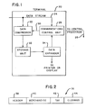
- Fig. 1 is a block diagram of a data terminal including data compression apparatus according to the invention and showing only those logic elements involved with the transmission of data from the terminal to a central processing unit (CPU);
- Fig. 2 is a block diagram illustrating the functional portions of a typical data message generated as the result of one type of merchandise transaction;
- Fig. 3 is a diagram illustrating the message format comprising the header portion of Fig. 2;
- Fig. 4 is a diagram illustrating the message format comprising the merchandise portion of Fig. 2;
- Fig. 5 is a diagram illustrating the message format comprising the tax portion of Fig. 2;
- Fig. 6 is a diagram illustrating the message format comprising the closing portion of Fig. 2;
- Fig. 7 is a more detailed diagram of the message format comprising the header portion of Fig. 3 showing the number of binary bits contained within each field in the message format together with a corresponding count of the
M 16 counter prior to data compression; - Fig. 8 is a diagram of the compressed data record produced as the result of a compression operation of the header portion of Fig. 7;
- Fig. 9 is a detailed block diagram of the data compression unit;
- Fig. 10 is a block diagram of the clock generator disclosed in Fig. 9;
- Fig. 11 shows the waveform of the clock pulses generated by the clock generator of Fig. 10;
- Fig. 12 shows the table of the electronic journal codes, the Qual codes and their coded representation;
- Fig. 13 shows the construction of the ID table located in the data compression unit of Fig. 9;
- Fig. 14 illustrates the manner in which Figs. 15A and 15B are to be arranged;
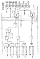
- Figs. 15A and 15B taken together disclose a block diagram of the Sequencer shown in Fig. 9;
- Fig. 16 illustrates the manner in which Figs. 17A and 17B are to be arranged;
- Figs. 17A and 17B taken together form a block diagram of the Media register disclosed in Fig. 9;
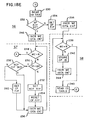
- Figs. 18A-18F taken together show in flow diagram form the operation of the preferred embodiment; and
- Fig. 19 is a state diagram of the operation of the preferred embodiment.
- Referring to Fig. 1, there is shown a block diagram of the data transmission system found within a data terminal device in which the present invention is utilized. Included in the
data terminal device 20 is adata compressor 22 coupled to acommunication bus 24 over which a stream of data bits is transmitted from theterminal 20 to a central processor (not shown) through acommunication control unit 28 and overcommunication bus 26 in a manner that is well-known in the art. When the central processor notifies thecommunication control unit 28 that it is in a disabled condition, therefore unable to accept any further data from theterminal 20, thecommunication control unit 28 generates control signals overline 30 to thedata compressor 22 notifying the compressor of such a condition and enabling thecompressor 22 to accept all data transmitted overbus 24. - After compressing the data received over
bus 24, thedata compressor 22 will transmit the compressed data to a RAM (random access memory)storage unit 32. When the central processor is again enabled to receive and process the data from thedata terminal 20, the compressed data is transmitted from thestorage unit 32 to a data expander 34 which expands the compressed data to its original form, the expanded data being displayed or printed and transmitted to thecommunication control unit 28 for transmission to the central processor overbus 26. - Referring now to Figs. 2-8 inclusive, there is shown details of the blocks of data in the form of a message generated as a result of the operation of the
data terminal 20 in a merchandise transaction. As diagrammed in Fig. 2, the format of atypical message 36 consists of aheader portion 38 which defines the type of message that is being generated together with various types of housekeeping data required to identify the environment in which the message is being generated, amerchandise portion 40 which includes data pertinent to the identity of the merchandise purchased, atax portion 42 and aclosing portion 44 which includes a total of the merchandise purchased. While Fig. 2 is illustrative of a typical message format found in present-day merchandise transactions, it is obvious that other combinations of merchandise and non-merchandise portions can also be included. - Referring now to Figs. 3-6 inclusive, there is shown in more detailed form the data included in the message 36 (Fig. 2). As shown in Fig. 3, the
header portion 38 includes, starting at the left end of the message format, acontrol character 00; a message count MSG CNT which is a consecutive number; a second control character C0; the store number, the number of thedata terminal 20 in which the data is generated; the transaction count which is a consecutive number identifying the transaction operation; a media count identifying the number of record slips generated; a Qual code which identifies the transaction as a cash, charge or other type of transaction; a sequential character identifying whether this is the only one or one of a number of transaction operations which make up a single overall transaction; the operator ID and a control character D indicating the end of the header portion. - The
merchandise portion 40 of themessage 36 is shown in Fig. 4 which includes a format character indicating the type of merchandise message format; a control character F which functions to separate the fields in the message format; the department number in which the transaction is being performed; a second control character F; the identification of the merchandise being purchased; a third control character F; a field-length character, SKU; the control character F, the quantity of merchandise being purchased; another control character F; the price of the merchandise being purchased; another control character F, an item code character indicating either a taxable or non-taxable transaction and a control character E indicating the end of themerchandise portion 40 of the message 36 (Fig. 2). - Fig. 5 discloses the tax portion 42 (Fig. 2) of the
message 36, which portion includes a tax code which may indicate a special tax being applied on the merchandise purchased; a number of control separator characters E, 9, and F; the amount of tax applied to the merchandise purchased; and a control character E' indicating the end of the taxedportion 42. Fig. 6 illustrates the closing portion 44 (Fig. 2) of themessage 36 which includes the control characters D, E and C, the latter indicating the end of themessage 36; and the total amount of the merchandised items purchased and which are described in themerchandise portion 40 of themessage 36. If more than one type of merchandise item is purchased during this transaction operation, it is obvious that themessage 36 will include amerchandise portion 40 and atax portion 42 for each type of merchandise item purchased, the total amount in theclosing portion 44 will then reflect the total amount of all merchandise items purchased by the customer. - In the present embodiment, the data compressor 22 (Fig. 1), upon receiving the message 36 (Fig. 2), will remove all information which is static or basic to the system during a specified time period. Thus, the date, the store number, the terminal number, and the format characters, the latter in the
merchandise portion 40, will be removed. Thedata compressor 22 will also remove all information which is the same or common to a previous transaction message if a positive association can always be made. An example of this type of operation is found in the operator ID and the type of transaction being performed. Thedata compressor 22 will also remove information which has a fixed relationship to a previous transaction message. An example of this is the transaction number which is always one more than the previous transaction number. The data compressor will also remove all information which can have an assumed value; it will record only if the information is different than the fixed assumed value. Examples of this type of data compression involve the quantity of merchandise items purchased which is assumed to be one, the type of transaction being performed and format control. Thedata compressor 22 will also abbreviate where appropriate. An example of this is in the operator ID where only the most significant bits of data are retained. - The
data compressor 22 will further remove information which is calculable from base information already collected. An example of this can be found in the transaction totals located in the closing portion 44 (Fig. 2) of themessage 36 and the tax amounts which are found in thetax portion 42 of the message 36 (Fig. 2) based on the purchased amounts. Thus, in processing the message 36 (Fig. 2), thetax portion 42 and the closingportion 44 may be dropped. Other areas in which thedata compressor 22 can reduce data include system redundant information and information not required to the desired end result. An example of the former may be found in the item price field in the merchandise portion 40 (Fig. 4); since the item code is known, the price can be found in price look-up tables if they are available. An example of the latter type of information concerns "no sales" transactions. In all of these situations, if the information is an exception to these rules, the data will be retained. Using these procedures, it has been found that thedata compressor 22 of the present embodiment can effect an overall data reduction of5 to 1. - Referring now to Fig. 7 there is shown a detailed diagram of the format of the
header portion 38 of the message 36 (Fig. 2) showing the number of 8-bit bytes of data assigned to each field in the message portion together with the output count of a 16-stage 4-bit binary counter found in thedata compressor 22 and used to keep track of the character position in the header portion being received by thecompressor 22. Fig. 8 shows the compresseddata record 46 of the header portion 38 (Fig. 7) after being compressed by thedata compressor 22. As indicated, the header portion is reduced from 176 binary bits to a possible 8 to 20 binary bits. Since the header portion 38 (Fig. 2) contains a greater amount of data that can be compressed than themerchandise portion 40, the explanation of the operation of thedata compressor 22 will be limited to the header portion 38 (Fig. 2) of themessage 36 recognizing that a similar operation utilizing the same compression apparatus can be applied to themerchandise portion 40. - As shown in Fig. 7, the
header portion 38 of themessage 36 includes, in addition to the fields described previously with respect to Fig. 3, an initial control character IC which indicates the start of themessage 36. Comparing the message formats of Fig. 7 and Fig. 8, it will be seen that the compresseddata record 46 consists of a formatcontrol character field 47, containing either a 4-bit format character SOTA or SOTg, each indicating the start of a transaction message. In the case of a string of character fields 47 where SOT or SOT may fall therein, it is implied that the format control character located therein terminates the last transaction message and starts the next transaction message. Thenext field 49 in the compresseddata record 46 is entitled electronic journal code representing the Qual code found in the header message 38 (Fig. 7), which code can be either 0 or 8 bits long. As will be described more fully hereinafter, if the electronicjournal code field 49 is 0 bits and the format control character is an SOTA, it is then assumed that the Qual code and the format code (found in themerchandise portion 40, Fig. 4) will represent a cash transaction together with a standard merchandise format. If the format control character is SOTB, it will then assume that the transaction is a standard "charge" transaction with a standard merchandise format. If the electronic journal code consists of a predetermined 4-bit character together with a SOTA, then it will be assumed that the transaction is a "cash" transaction; a "charge" transaction is implied if the control character is SOTg. The format code will be specified by a single 4-bit character located in the electronic journal code field. If the transaction code is other than a (cash) or (charge), the electronicjournal code field 49 will contain the specific two 4-bit characters specifying the code. In a typical merchandising operation, there may be up to 30 different transaction codes. - Referring again to Fig. 8, the compressed
data record 46 which is stored in the RAM storage unit 32 (Fig. 1) contain anoperator ID field 51 in which may be recorded 0 bits indicating that the operator is the same as in theprevious header portion 38, or a 4-bit character, indicating the specific operator ID. Therecord 46 is completed with the generation of a 4-bit record separator character EORF located in therecord separator field 53 indicating the end of the compressed data record if a merchandise field is to follow. If anew header portion 38 is to start, one of the format control characters SOTA or SOTB will be stored in thefield 53. As will be described more fully hereinafter, the total number of bits found in the compresseddata record 46 provide an indication as to whether new data pertaining to the operator I.D. or the electronic journal code or to both is present. - Referring now to Fig. 9 there is shown the logic of the data compressor 22 (Fig. 1) for compressing data received serially in a bit-by- bit format from the transmission bus 24 (Fig. 1). Included in the
data compressor 22 is abus monitor unif 48 including the necessary interface and control logic to properly interface the data compressor to the systemterminal communication bus 24. The bus monitor 48 also includes astatus decoder 50 connected to the communication control unit 28 (Fig. 1) overline 30 for receiving signals indicating whether the central processor is capable of receiving data from the terminal 20. The bus monitor 48 also includes an 8-bit register 52 for storing an 8-bit character received from thecommunication bus 24 and an interrupt flip-flop 54 which outputs an interrupt signal INT upon the storing of an 8- bit character in theregister 52. - The interrupt signal INT is outputted over
line 56 from the flip-flop 54 to a 16-stage (4-bit binary) M16 counter 58 (Fig. 9) which is used to keep track of the position of each character in theheader portion 38 of themessage 36 as being received by thebus monitor 48. Thecounter 58 essentially counts the number of interrupt signals generated by the flip-flop 54 and is enabled upon the sensing of avalid message 36 by acharacter decoder 82. The output counts M16-0-M16-15 ofcounter 58 are outputted to asequencer 60 and a timingcontrol logic unit 62 for controlling the various operations of the data compressor. As shown in Fig. 7, the output counts of the M16 counter 58 occur after the character or characters in each field of theheader portion 38 have been inputted into theregister 52. For example, after the SEQ character has been loaded into theregister 52 resulting in the outputting of an interrupt signal from the flip-flop 54, theM16 counter 58 will output count 14 designated as M 16-14 overline 64 to thesequencer 60 and thetiming control 62 unit, the latter outputting a control signal TC for initiating a logic operation of the data compressor at this time. Thetiming control 62 receives a series of clock pulses T1 -T8 from a clock generator 66 (Fig. 9). As shown in Fig. 10, theclock generator 66 comprises anoscillator 68 outputting a series of clock pulses to a three-stage binary counter 70 whose output is fed into a 3 to 8decoder 72 which outputs the clock pulses T1 T8. The waveform of these clock pulses are shown in Fig. 11 which also includes the interrupt pulse INT outputted from the flip-flop 54 which occurs from T1-T4 clock time if thedecoder 50 indicates the CPU is disabled and an 8-bit character is ready inregister 52. - In response to the generation of the interrupt signal INT, the 8-bit character stored in the
register 52 is outputted in parallel, under the control of thetiming control unit 62, overcable 74 to amedia register 76, atransaction register 78, an electronics journal (EJ) table 80, acharacter decoder 82 and amultiplexer 84. The media register 76 is shown in more detailed form in Fig. 17A and 17B, and is a 16-bit parallel in-parallel out register in which the media count or data (Fig. 7) from the most current header portion 38 (Figs. 2 and 7) being compressed is stored. As shown in Figs. 17A and 17B, the character bits indicated as P10-P17, are inputted overcable 74 to a series of flip-flops register 52, the flip-flop 54 will output the interrupt signal INT overline 56 resulting in theM 16counter 58 outputting the count M 16-11. This signal will appear as timing control signal TC-11 (Fig. 17A) which, together with the interrupt signal INT and a second timing control signal TC-4 generated in thesequencer 60, are fed to an ANDgate 88 which enables the first character of the media data to be loaded into the flip-flops 86A. The same condition occurs when the second character of the media data is loaded into theregister 52 and theM 16 counter outputs the count M16-12 as a result of the generation of the interrupt signal from the flip-flop 54. Since the media data of thelast message 36 compressed by thedata compressor 22 is the only media data required prior to the time the central processor is enabled to accept data from the terminal device, the data stored in the media register 76 will be outputted at the appropriate time overcable 92 containing 16 conductors to amultiplexer 94 for subsequent transmission to the data expander 34 (Fig. 1). - The transaction register 78 (Fig. 9) is a 16-bit parallel in-parallel out register similar in construction to that of the media register 76 and in which the transaction number of the first compressed header is stored. Since the transaction number of each succeeding message is one more than the previous compressed message, by storing the transaction number of the first compressed header in the
transaction register 78, the data expander 34 (Fig. 1) can recreate the transaction number of each succeeding compressed message stored in the storage media 32 (Fig. 1) by adding one to the previous transaction number. Thetransaction register 78 includes a flip-flop 79 which when set upon the storing of the first transaction number will prevent the entry of any succeeding transaction number until reset upon the ending of a compression operation. - The electronics journal (EJ) table 80 (Fig. 9) comprises a storage unit and associated programmable logic arrays including the EJ flip-
flop 81 for outputting an electronics journal code for the Qual code (Fig. 7) located in the header portion 38 (Fig. 2). The configuration of the EJ table is shown in more detail in Fig. 12 in which the various Qual codes found in a merchandising operation are listed incolumn 83 with their corresponding EJ code (column 85) together with a corresponding format control character SOTA (column 87) and SOTg (column 89). The Qual code defines the type of transaction which is involved in the current terminal operation. Thus, if the Qual code is 01, the transaction is a cash transaction. If the Qual code is 03, the transaction is a charge transaction. Since 90% of all the transactions comprise either of these two types of transaction codes, the storing of the character SOTA in the field 47 (Fig. 8) of the compresseddata record 46 together with no bits in the electronicsjournal code field 49 indicates that it is a cash transaction. If the format control character stored is an SOTg, the combination indicates that the transaction will be a charge transaction. If the Qual code is other than these two Qual codes, 01 or 03, the specific 8-bit electronics journal code listed (column 85) in Fig. 12 will be stored in the electronicjournal code field 49 in the compressed data record 46 (Fig. 8) allowing the data expander 34 (Fig. 1) to reconstruct from the compresseddata record 46 the original Qual code of thedata message 36. The storing of one of the characters SOTA or SOTe in thefield 49 of the compressed data record 46 (Fig. 8), also notifies thedata expander 34 the start of a compressed data message, thereby eliminating the need for storing control characters such as 1 C and 1 D in the position shown in theheader portion 38 in Fig. 7. - The character decoder 82 (Fig. 9) continuously monitors the output of the
register 54 for the occurrence ofcharacters 01, 1C or 1 D. The character 1C indicates the start of theheader portion 38 while 1 D indicates the end of the header portion. Thecharacter 01 is found in the message count field (MSG CNT) (Fig. 7) indicating that it is the first message of a number of messages concerned with the same merchandise transaction being performed by the data terminal device 20 (Fig. 1). Included in thecharacter decoder 82 is an IC flip-flop 98 which when set will output a pulse to initiate the operation of thebinary counter 58, an ID flip-flop 100, and an 01 flip-flop 102, whose outputs are transmitted to thesequencer 60 and theM 16 counter 58 (Fig. 9). - The output of the
shift register 52 in theBus Monitor 48 is also transmitted through themultiplexer 84 to an ID table 104 in which the operator ID of thecurrent header 38 is compared with the previous operator IDs stored in the table to determine if the operator ID of thecurrent header portion 38 is the same as the operator ID of the previous message. If it is the same, the operator ID field in the compressed data record (Fig. 8) will contain no bits, which notifies thedata expander 34 that the operator ID of the current compressed data record is the same as that of the previous compressed data record. If the operator ID is not the same as the previous operator ID, four bits of data identifying the current operator ID will be stored in the compresseddata record 46 and in the ID table 104. The ID table 104 is a 256x8 static RAM memory unit which is used to store the operator ID characters read from theheader portion 38 and also a corresponding 4-bit character which is to be stored in the compressed data record (Fig. 8). The use of a 4-bit ID character allows (for up to) sixteen unique operator ID characters which is sufficient to cover this area of the merchandising operation. - As shown in more detail in Fig. 13, the ID table 104 includes a plurality of storage fields to accommodate sixteen
records 103, each field includes an AF flip-flop 105 (Fig. 9) indicating the storage of an operator ID in that field and a PTF flip-flop 107 indicating the last field in which an operator ID is stored, therecord 103 comprising eight bytes of data wherein each byte is equivalent of two 4-bit characters. Also included in the ID table is atemporary file portion 106 in which the seven operator ID characters from theheader portion 38 being currently processed are stored. Associated with the ID table 104 is a WC (Word)counter 108, anID register 110, aID TA counter 112 and a comparator unit 114. TheWC counter 108 is a 4-bit binary counter which supplies the word address (column 105B) (Fig. 13) of the operator ID characters stored in thetemporary file 106 and for the storage of the operator ID in the ID table 104. Thecounter 108 is operated by the interrupt signal INT generated overline 56 from the flip-flop 54 and outputs its count to thesequencer 60 and also to amultiplexer 116 overline 118 for transmission to the ID table 104. Thecounter 108 receives the output of the M16 counter 58 overline 120 for use in generating its output in a manner that is well-known in the art. - The ID register 110 (Fig. 9) is an 8-bit parallel in-parallel out register required for the temporary storage of data read out of the ID table 104 during the operation of comparing the operator ID of the
current header portion 38 with the operator's ID stored in the ID table 104. TheIDTA counter 112 is an 8-bit binary address counter which generates the address, (column 105A) (Fig. 13) together with the output of the WC counter 108 (column 105B) (Fig. 13) for accessing the ID table 104. The comparator 114 compares eight bits of data representing the current operator ID stored in the temporary file 106 (Fig. 13) against eight bits representing a previous operator ID originally stored in the ID table 104, and which are now buffered in theID register 110. The comparator 114 includes a CF flip-flop 122 which outputs signals CF, CF to thesequencer 60 upon finding a coincidence between the operator ID stored in theID register 110 and the last operator ID character stored in the ID table 104. If a comparison is not found, a NCF flip-flop 124 is set, generating a signal to thesequencer 60 resulting in thetiming control logic 62 generating the appropriate control signals TC to a read/write logic unit 126 which will write in the current operator ID characters in the ID table 104. - Other elements included in the data compressor logic include a
character encoder 128 which outputs the correct bit configuration for the record separator character "EORF" which is the last character in the compresseddata record 46 shown in Fig. 8, the character being transmitted through amultiplexer 130 for transmission of the character into thestorage media 32, Figs. 1 and 9. Thestorage unit 32 in the present embodiment may comprise a lKx4 static RAM memory which is used to store the compressed header records. Also inputted into themultiplexer 130 for storage in thestorage unit 32 is the electronic journal code and its associated SOT character outputted from the EJ table 80 (Fig. 13) and the operator ID outputted from theID register 110. The operation of theRAM memory unit 32 is under the control of a 10-bitbinary address counter 134 which generates the address for accessing theRAM memory unit 32 in a manner that is well-known in the art. Also included in thedata compressor 22 is a conventional power supply 140 (Fig. 9) which outputs a pair of signals, power up and power down, overline 142 to thesequencer 60. - Referring to Figs. 15A and 15B there is shown in detail the logical elements of the sequencer 60 (Fig. 9) which includes four
conventional LS 107 J-K flip-flops 144 whose outputs are transmitted to a conventional 4-16 output 74154multiplexer 146 which outputs in sequence ten control signals SO-S10 for transmission to thetiming control 62 overcable 148 which effects the outputting in a predetermined sequence of the timing control signals TC for operating the data compressor in states 0-10 as illustrated in Fig. 19 and in a manner that will be described more fully hereinafter. The outputs of themultiplexer 146 are labeled in Fig. 15A in hexadecimal code which is the code used to represent the data characters on the present system. As further shown in Figs. 15A and 15B, thesequencer 60 includes an array of logical gates which operate in a well-known manner and which receive signals from the logic blocks disclosed in Fig. 9 for enabling the orderly operation of thedata compressor 32. The identification of the various input signals to thesequencer 60 will be described more fully in conjunction with the description of the operation of the data compressor 22 (Fig. 1) with respect to the flow diagrams shown in Figs. 18A-18F inclusive. - The flow diagrams of Figs. 18A-18F inclusive will now be described in conjunction with the state diagram of Fig. 19 which illustrates the operation of the
data compressor 22 with respect to the presence of the various counts of theM16 counter 58, the presence of clock pulse T8 and various other control signals generated as part of the orderly operation of thedata compressor 32. - Referring to Fig. 18A, the
data compressor 22 will be in an idle state (block 150) (state 1, Fig. 19) with the bus monitor 48 (Fig. 9) monitoring the status decoder 50 (block 152) to see if a signal has been received from the communication control unit 28 (Fig. 1) indicating that the central processor has been disabled. Thecompressor 22 will stay in this loop as long as thedecoder 50 indicates that the central processor is still receiving data from the terminal. When thestatus decoder 50 indicates that the central processor has been disabled, it will generate an interrupt which notifies the compressor (block 156) of such a condition. Thecompressor 22 will then monitor the output of theregister 52, checking for the presence of the character IC (block 158) which indicates the start of the header portion 38 (Fig. 2) of themessage 36. If the character sensed is not IC, the compressor will go back to point A (block 154) until it detects the character IC. This detection occurs in the character decoder 82 (Fig. 9) which sets the IC flip-flop 98 outputting the control signal IC to the M16 counter 58 which outputs count 1 (Fig. 8). The compressor will then check for the next interrupt (block 160) indicating that thecontrol character 00 is now stored in theregister 52. Thecompressor 22 will ignore thecharacter 00 and check for the next interrupt (block 162) indicating that the next character, MSG CNT is stored in theregister 52. The compressor will check the MSG CNT character for a 01 indicating that it is the first message of the current transaction operation (block 164). If the character is not 01, but some other number indicating that anothermessage 36 having thesame header portion 38 of the same transaction has already been compressed by thecompressor 22 and therefore thisheader portion 38 is redundant and can be ignored, the compressor will go into state 2 (Fig. 19) and check the interrupts (block 166) until it detects the character ID (block 168) indicating the end of theheader portion 38 of the current message. The compressor will then leave state 2 (Fig. 19) and return to point A (block 154) instate 1 to check for theheader portion 38 of the next message 36 (Fig. 2). - If the
compressor 22 detected thecharacter 01 in the MSG CNT field, the compressor will go to state 3 (Fig. 19) by checking for the next interrupt signal (block 170). Upon detecting the next interrupt signal indicating the next character is being outputted by theregister 52 over cable 74 (Fig. 9), the compressor will increment the M16 counter 58 by 1 (block 172) and this sequence of events will be repeated until the counter reaches the count of 9 (block 174). Referring to Fig. 7, it will be seen that by incrementing the M16 counter to a count of 9, the control field character CC, the store number characters, and the terminal number characters will be ignored, since this data can be determined without referring to themessage 36 and is the same for eachheader portion 38 generated by theterminal device 20. - At
count 9, the compressor will check (block 176) to see if the TRS flip-flop 79, located in the transaction register 78 (Fig. 9), has been set indicating that the first transaction character has been stored in thetransaction register 78. If the flip-flop 79 has not been set, the compressor will store the most significant transaction character (block 178) in the transaction register 78 (Fig. 9) and then wait for the next interrupt (block 180) at which time theM16 counter 58 will output count 10. Upon receiving the next interrupt which indicates that the second transaction character is being outputted from the register 52 (Fig. 9), thecompressor 22 will store the second or least significant transaction character (block 182) in thetransaction register 78; wait for the next interrupt (block 184) and then set the TRS flip-flop 79 (block 186). The setting of the 1 ''5 flip-flop 79 flags the compressor that the transaction number of the first message compressed by thedata compressor 32 is already stored in thetransaction register 78, and that all the transaction numbers of all subsequent messages can be ignored, since the data expander 34 (Fig. 1) need only know the transaction number of the first message compressed to determine the transaction numbers of each of the subsequent messages compressed by the data compressor since the numbers are in consecutive order. Thus, in the case of the second message transmitted to thedata compressor 22, the compressor upon checking the TRS flip-flop 79 to see if it is set (block 176) and finding that it is set will then wait for the next interrupt (block 177) indicating the presence of the least significant transaction character in theregister 52. Thecompressor 22 will ignore this interrupt and then check for the next interrupt (block 184) indicating the storage of the first or most significant media character in theregister 52. TheM16 counter 58 will output count 11 at this time. Since the TRS flip-flop 79 is already set, the compressor will enter state 4 (Fig. 19), which occurs when the M16 counter 58 (Fig. 9) is at count 11 and clock pulse T8 (Fig. 11) has been generated (Fig. 19). At count 11, thecompressor 22 will store (block 188) the most significant media character in the media register 76 (Fig. 9) and then wait for the next interrupt (block 190). - Upon the occurrence of the next interrupt which increments the M16 counter 58 to
output count 12, thecompressor 22 will store the least significant media character (block 192) in the Media register 76 (Fig. 9) and wait for the next interrupt (block 194) which indicates that the Qual code character is being outputted from the register 52 (Fig. 9). Thecompressor 22 will read the EJ table 80 (Fig. 12) (block 196) using the Qual code character (column 83) as an address and store the corresponding format control character SOT or SOT (block 198) in the field 47 (Fig. 8) of the compressed data record 46 (Fig. 8) stored in the storage unit 32 (Fig. 9), increment (block 200) the address counter 134 (Fig. 9) and check the Qual code character for either a 01 or 03 (block 202). As described previously, if the Qual code character is either 01 or 03, the storing of the format control character SOT or SOTg with no bits located in the electronicjournal code field 49 of the compressed data record 46 (Fig. 8) enables the expander 34 (Fig. 1) to reconstruct from the compressed data the proper Qual code. If the Qual code character was not 01 or 03, thecompressor 22 will store the most significant EJ character (block 204) in the RAM storage unit 32 (Fig. 1 increment (block 206) the address counter 134 (Fig. 9), store the least significant EJ character (block 208) in thestorage unit 32 and again increment (block 210) the address counter 134 (Fig. 9). The incrementing of theaddress counter 134 will result in the EJ flip-flop 81 outputting a signal EJ to thesequencer 60. As shown in Fig. 19, the generation of the signal EJ together with thecount 13 of theM 16counter 58 results in thecompressor entering state 5 at Point C (Fig. 18B and 18C). - Referring to Fig. 18C, it will be seen that the
compressor 22 upon enteringstate 5, will wait for the next interrupt (block 212) indicating that the next character SEQ (Fig. 7) in theheader portion 38 is now being outputted by theregister 52. The output of theM 16counter 58 will at this time be atcount 14. Thecompressor 22 resets (block 214) the WC counter 108 (Fig. 9); increment the WC counter (block 216) and waits for the next interrupt (block 218) at which time theM16 counter 58 will output count 15. The generation of this next interrupt indicates that the most significant operator ID character is now being outputted from the register 52 (Fig. 9) overcable 74 throughmultiplexer 84 to the temporary file 106 (Fig. 13) of the ID table 104 (block 220). Thecompressor 22 then increments the WC counter 108 (block 222) and waits for the next interrupt signal to occur (block 224) which increments the M16 counter 58 tooutput count 16. When this interrupt signal occurs, the compressor will check the character being outputted from theregister 52 to see if it is an ID character (Fig. 7) indicating the end of the header portion 38 (block 226). If the character is not an ID character, the compressor will go back to block 222 and store that character which in this case would be the next operator ID character. Theword counter 108 is then incremented to provide the address of the next operator ID character for storage in the temporary file 106 (Fig. 13). This sequence of events will continue until all seven operator ID characters are stored in thetemporary file 106, at which time, the compressor will detect the end of header character ID, and then reset (block 228) theWC counter 108 and the IDTA counter 112 (Fig. 9) preparatory to comparing the operator ID character now stored in thetemporary file 106 with the last operator ID stored in the ID table 104 (Fig. 13). In addition tocounters flop 122 and the NCF flip-flop 124 located in the comparator 114 (Fig. 9) will be reset. - Referring to Fig. 13, it will be seen that the first bit in the 0 word location in the first field in the ID table 104 is labeled AF, which is the output of the flip-flop 105 (Fig. 9) and which is set to a logical one whenever its associated record field has stored therein an operator ID. The first bit in the eighth or last word location of the same field is labeled PTF and is the output of the flip-flop 107 (Fig. 9) and is set to a logical one if this is the last field in the ID table 104 in which the seven 8-bit characters of an operator ID is stored. The function of the flip-
flops current header portion 38 is the same as theprevious header portion 38. - Referring to Fig. 18D, the
compressor 22 will read (block 230) thefirst record 103 in the ID table 104 (Fig. 13) and the AF flip-flop in that field is checked to see if it is set (block 232). At this time, the compressor will enter state 6 (Fig. 19). If the AF flip-flop 105 in the first field is not set, indicating an empty record, and which normally occurs when thefirst header portion 38 is processed by thecompressor 22, thecompressor 22 will set (block 234) the AF flip-flop 105 (Fig. 9) in that field and increment (block 236) theWC counter 108 and the IDTA counter 112 (Fig. 9) whose outputs will provide the address of the first character or word location in thefirst record 103 of the ID table 104 (Fig. 13). Thecompressor 22 will check the output count of the WC counter 108 (block 238) to see if it is at 8, indicating that the seven characters of the operator ID have been stored in the first field or the ID table 104. At this time the compressor enters state 8 (Fig. 19). If theWC counter 108 is not atcount 8, the compressor will store (block 242) the operator ID character in the field location whose address is the output count of thecounters WC counter 108 and the IDTA counter 112 to provide the address of the next field location. This process will continue until all seven characters of the operator ID are stored in the first field of the ID table 104. At this time, the output of theWC counter 108 is at 8 (block 238) and the compressor will read (block 240) the ID table to output the operator ID character to theID register 110 for storage in thefield location 51 of the compressed data record 46 (Fig. 8) located in the RAM memory 32 (Fig. 9). - If the
compressor 22 upon reading the first record in the ID table (block 230) finds that the AF flip-flop 105 (Fig. 9) in that field is set (block 232) indicating an occupied field, the compressor.22 will increment theWC counter 108 and the IDTA counter 112 (block 246) and check the output of theWC counter 108 for the presence of an 8 count (block 248) which would indicate that the operator ID characters of thecurrent header portion 38 have been compared with the operator ID characters stored in the first field of the ID table 104. At this time, the compressor enters state 7 (Fig. 19). If the output count of theWC counter 108 is not 8, thecompressor 22 will output the current operator ID characters stored in thetemporary file 106 to theID register 110 from which the characters are then transmitted to the comparator 114 which compares (block 250) the current operator ID characters with the characters stored in the first field location of the ID table 104 (Fig. 13). If the comparator 114 finds that the operator ID characters are identical, the compressor will check to see if the NCF flip-flop 124 (Fig. 9) is set (block 258). If the NCF flip-flop 124 is not set, the compressor will set the CF flip-flop 122 (block 260) and increment theWC counter 108 and the IDTA counter 112 (block 256) and then check the output count of theWC counter 108 for the presence of an 8 count (block 248). - If, in comparing the operator ID characters of the
current header portion 38 with the operator ID characters stored in the ID table 104, the comparator 114 finds that the operator ID's do not compare, the comparator 114 will set the NCF flip-flop 124 (block 252), reset (block 254) the CF flip-flop 122 and then the processor will increment theWC counter 108 and the IDTA counter 112 (block 256). This sequence of operations will continue until the output of theWC counter 108 is equal to 8, at which time the compressor will read the next record in the ID table 104 (block 268) (Fig. 18F) for comparing the operator ID characters stored in that record with the current operator ID characters stored in the ID register 110 (Fig. 9). At this time the compressor enters state 10 (Fig. 19). Thecompressor 22 will then check the output of the comparator 114 to see if the CF flip-flop 122 is set (block 270). If the flip-flop 122 is not set, the signal NCF from the flip-flop 124 will be outputted to thesequencer 60 indicating that there is no comparison between the current header operator ID character and the operator ID record stored in ID table (Fig. 13). Thecompressor 22 resets (block 272) the PTF flip-flop 107 (Figs. 9 and 13) of the record field in the ID table 104 just compared. The resetting of the PTF flip-flop 107 indicates that the operator ID characters of thecurrent header portion 38 are not equal to the previous field in the ID table just compared. Thecompressor 22 then resets (block 274) theWC counter 108 in preparation for comparing the operator ID characters of thecurrent header portion 38 with the operator ID characters found stored in the next record field in the ID table 104 (Fig. 1) and will return to state 6 (Fig. 19). This operation of the comparator 114 will continue until the compressor finds a comparison (block 270) (Fig. 18F) between the operator ID characters of thecurrent header portion 38 and one of the operator ID character records 103 in the ID table 104 or it finds a record in which the AF flip-flop 105 (Figs. 9 and 13) is not set (block 232). This condition indicates thisrecord portion 103 of the ID table 104 is empty and none of the previously compared records compare with the operator ID of thecurrent header portion 38. The current operator ID is then stored in theempty record portion 103 of the ID table 104 and the AF flip-flop 105 will be set (block 234) (Fig. 18D) indicating the last field in the ID table 104 in which an operator ID is stored. - If a comparison is found between the current operator ID characters (block 270) (Fig. 18F) and one of the
records 103 in the ID table 104, thecompressor 22 must determine if that record contains the operator ID characters of thelast header portion 38 processed, in which case theoperator ID field 51 in the compressed data record 46 (Fig. 8) is left blank. As described previously, this condition allows the expander 34 (Fig. 1) to reconstruct from the previous header portion the operator ID of the current header portion. If no comparison is found with any of therecords 103 in the ID table 104, thecompressor 22 will store in theoperator ID field 51 of the compressed data record 46 (Fig. 8) four data bits representing the operator ID of thecurrent header portion 38 and the seven characters of the current operator ID in the firstunoccupied record 103 of the ID table 104. After finding a comparison (block 270), thecompressor 22 will check to see if the PTF flip-flop 107 is set (block 276). If the PTF flip-flop 107 is set indicating that thisrecord portion 103 in the ID table 104 contains the operator ID characters from the last processedheader portion 38, thecompressor 22 will skip theoperator ID field 51 in the compressed data record 46 (Fig. 8) (block 278) and store the end of word character EORF in the memory unit 32 (Fig. 9) outputted from thecharacter encoder 128. Thecompressor 22 then increments (block 280) the address counter 134 (Fig. 9) before returning into the idle state one (Fig. 19) preparatory to compressing the next portion of themessage 36 received by thebus monitor 48. - If the
compressor 22 in checking the PTF flip-flop 107 (block 276) finds the flip-flop in a reset condition (PTF is a logical one) indicating that the matched operator ID's are not equal to thelast header portion 38 processed, thecompressor 22 will store (block 262) (Fig. 18E) the last four bits of the operator ID outputted from theID register 110 and the end of word character EORF outputted from thecharacter encoder 128 in the compressed data record 46 (Fig. 8) located in theRAM memory 32. The compressor then sets (block 264) the PTF flip-flop 107 and increments (block 266) the address counter 134 (Fig. 9) before returning to the idle state (point A) preparatory to compressing the next character outputted from theregister 52. - Referring to Fig. 8, it will be seen that if the total number of bits in the compressed
data record 46 is 8, the expander 34 (Fig. 1) will know that there are no bits infields - While the present embodiment of the
data compressor 22 has been described with respect to the off-line operation of the terminal upon the disabling of the central processor to receive any more data from the terminal, it is obvious that the data compressor can be used in those situations where the total amount of compressed data generated during a day's operation of the terminal can be stored within a memory unit contained in the terminal itself, thereby eliminating any need or expense of the central processor. As shown in Fig. 8, the data compressor can compress theoriginal header portion 38 consisting of up to 176 bits of data to acompressed data record 46 of from 8 to 20 bits, thereby realizing a reduction of up to 8 to 1 in this portion of the message. As was described previously, the compression of the data in the manner disclosed would also result in the elimination of the tax portion 42 (Fig. 2) and the closingportion 44 of themessage 36 thereby providing a further reduction in the amount of data required to be stored in thememory unit 32.
Claims (11)
Applications Claiming Priority (2)
| Application Number | Priority Date | Filing Date | Title |
|---|---|---|---|
| US05/914,821 US4232375A (en) | 1978-06-12 | 1978-06-12 | Data compression system and apparatus |
| US914821 | 1978-06-12 |
Publications (3)
| Publication Number | Publication Date |
|---|---|
| EP0016050A1 EP0016050A1 (en) | 1980-10-01 |
| EP0016050A4 EP0016050A4 (en) | 1980-10-09 |
| EP0016050B1 true EP0016050B1 (en) | 1983-02-16 |
Family
ID=25434811
Family Applications (1)
| Application Number | Title | Priority Date | Filing Date |
|---|---|---|---|
| EP79900686A Expired EP0016050B1 (en) | 1978-06-12 | 1980-01-29 | Apparatus and method for compressing data |
Country Status (5)
| Country | Link |
|---|---|
| US (1) | US4232375A (en) |
| EP (1) | EP0016050B1 (en) |
| JP (1) | JPS55500490A (en) |
| DE (1) | DE2964795D1 (en) |
| WO (1) | WO1980000107A1 (en) |
Families Citing this family (26)
| Publication number | Priority date | Publication date | Assignee | Title |
|---|---|---|---|---|
| JPS56140451A (en) * | 1980-03-31 | 1981-11-02 | Hitachi Ltd | Log information holding device |
| JPS57169865A (en) * | 1981-04-14 | 1982-10-19 | Fuji Xerox Co Ltd | Picture information storage device |
| US4545032A (en) * | 1982-03-08 | 1985-10-01 | Iodata, Inc. | Method and apparatus for character code compression and expansion |
| US4574351A (en) * | 1983-03-03 | 1986-03-04 | International Business Machines Corporation | Apparatus for compressing and buffering data |
| DE3482901D1 (en) * | 1983-05-11 | 1990-09-13 | Hitachi Ltd | TEST DEVICE FOR REDUNDANCY STORAGE. |
| EP0204763A4 (en) * | 1984-11-16 | 1989-03-09 | Konstantine Beridze | Data compressing computer system and process thereto. |
| US5434568A (en) * | 1985-01-10 | 1995-07-18 | Moll; Edward W. | Data compression by removing repetition and unnecessary information |
| US4682150A (en) * | 1985-12-09 | 1987-07-21 | Ncr Corporation | Data compression method and apparatus |
| US4949302A (en) * | 1986-11-17 | 1990-08-14 | International Business Machines Corporation | Message file formation for computer programs |
| US5146221A (en) * | 1989-01-13 | 1992-09-08 | Stac, Inc. | Data compression apparatus and method |
| US5532694A (en) * | 1989-01-13 | 1996-07-02 | Stac Electronics, Inc. | Data compression apparatus and method using matching string searching and Huffman encoding |
| US5226156A (en) * | 1989-11-22 | 1993-07-06 | International Business Machines Corporation | Control and sequencing of data through multiple parallel processing devices |
| US5481704A (en) * | 1991-09-27 | 1996-01-02 | Computer Concepts Corp. | Indexing/compression scheme for supporting graphics and data selection |
| CZ286929B6 (en) * | 1993-08-05 | 2000-08-16 | Motorola Inc | Telefax communication process within a communication system with selective calling and communication system for making the same |
| US6076084A (en) * | 1994-01-03 | 2000-06-13 | Norton-Lambert Corp. | File transfer method and apparatus utilizing delimiters |
| US5446888A (en) * | 1994-01-14 | 1995-08-29 | Pyne; Charles F. | Remote file transfer method and apparatus |
| US5978805A (en) * | 1996-05-15 | 1999-11-02 | Microcom Systems, Inc. | Method and apparatus for synchronizing files |
| AUPP702498A0 (en) * | 1998-11-09 | 1998-12-03 | Silverbrook Research Pty Ltd | Image creation method and apparatus (ART77) |
| IL129008A (en) * | 1999-03-16 | 2001-08-26 | Netstrap Ltd | Method of encoding binary data |
| US6400293B1 (en) * | 1999-12-20 | 2002-06-04 | Ric B. Richardson | Data compression system and method |
| US6380873B1 (en) * | 2000-06-30 | 2002-04-30 | Quantum Corporation | Method for reducing radio frequency emissions on high-speed serial buses |
| TWI241502B (en) * | 2002-12-26 | 2005-10-11 | Ind Tech Res Inst | Real time data compression apparatus for a data recorder |
| US8489492B2 (en) * | 2011-04-06 | 2013-07-16 | International Business Machines Corporation | Automated encoding of increment operators |
| US8972497B2 (en) * | 2011-04-06 | 2015-03-03 | International Business Machines Corporation | Automated encoding of field operators for absent fields |
| US10360626B2 (en) * | 2011-04-06 | 2019-07-23 | International Business Machines Corporation | Securities messages with automated encoding of field operators |
| US8983866B2 (en) | 2011-04-06 | 2015-03-17 | International Business Machines Corporation | Automated encoding of delta operators |
Family Cites Families (16)
| Publication number | Priority date | Publication date | Assignee | Title |
|---|---|---|---|---|
| US3311893A (en) * | 1963-08-29 | 1967-03-28 | Sperry Rand Corp | Memory organization wherein only new data bits which are different from the old are recorded |
| US3413611A (en) * | 1966-01-17 | 1968-11-26 | Pfuetze David | Method and apparatus for the compaction of data |
| US3501750A (en) * | 1967-09-19 | 1970-03-17 | Nasa | Data compression processor |
| US3535696A (en) * | 1967-11-09 | 1970-10-20 | Webb James E | Data compression system with a minimum time delay unit |
| US3564512A (en) * | 1968-10-18 | 1971-02-16 | Hewlett Packard Co | System for compacting and expanding data |
| US3613086A (en) * | 1969-01-03 | 1971-10-12 | Ibm | Compressed index method and means with single control field |
| US3612660A (en) * | 1969-09-08 | 1971-10-12 | Wendell S Miller | Digital data compaction |
| US3675211A (en) * | 1970-09-08 | 1972-07-04 | Ibm | Data compaction using modified variable-length coding |
| US3717851A (en) * | 1971-03-03 | 1973-02-20 | Ibm | Processing of compacted data |
| US3772654A (en) * | 1971-12-30 | 1973-11-13 | Ibm | Method and apparatus for data form modification |
| US4021782A (en) * | 1974-01-07 | 1977-05-03 | Hoerning John S | Data compaction system and apparatus |
| CA1071332A (en) * | 1974-05-01 | 1980-02-05 | Toshio Kashio | Data processing system |
| US3936808A (en) * | 1974-09-03 | 1976-02-03 | Ultronic Systems Corporation | Data storage and processing apparatus including processing of repeat character sequences |
| JPS5524134B2 (en) * | 1974-11-15 | 1980-06-27 | ||
| US3976844A (en) * | 1975-04-04 | 1976-08-24 | Honeywell Information Systems, Inc. | Data communication system for transmitting data in compressed form |
| US4145686A (en) * | 1977-06-27 | 1979-03-20 | Recognition Equipment Incorporated | Data compressor |
-
1978
- 1978-06-12 US US05/914,821 patent/US4232375A/en not_active Expired - Lifetime
-
1979
- 1979-06-11 WO PCT/US1979/000409 patent/WO1980000107A1/en not_active Ceased
- 1979-06-11 DE DE7979900686T patent/DE2964795D1/en not_active Expired
- 1979-06-11 JP JP50097179A patent/JPS55500490A/ja active Pending
-
1980
- 1980-01-29 EP EP79900686A patent/EP0016050B1/en not_active Expired
Also Published As
| Publication number | Publication date |
|---|---|
| WO1980000107A1 (en) | 1980-01-24 |
| JPS55500490A (en) | 1980-08-07 |
| EP0016050A1 (en) | 1980-10-01 |
| DE2964795D1 (en) | 1983-03-24 |
| EP0016050A4 (en) | 1980-10-09 |
| US4232375A (en) | 1980-11-04 |
Similar Documents
| Publication | Publication Date | Title |
|---|---|---|
| US4232375A (en) | Data compression system and apparatus | |
| EP0166023B1 (en) | Method and system for data compression and restoration | |
| US4872009A (en) | Method and apparatus for data compression and restoration | |
| CA1038500A (en) | Scan and read control apparatus for a disk storage drive in a computer system | |
| CA1273432A (en) | High capacity disk storage system having unusually high fault tolerance level and bandpass | |
| US4016548A (en) | Communication multiplexer module | |
| US4314356A (en) | High-speed term searcher | |
| EP0425851B1 (en) | Apparatus for decoding frames from a data link | |
| US4031515A (en) | Apparatus for transmitting changeable length records having variable length words with interspersed record and word positioning codes | |
| CA1183958A (en) | High speed search system | |
| US3805249A (en) | Format hard copy display apparatus for a data processing printout system | |
| US4380029A (en) | Data recording format and method and apparatus for producing same | |
| JPH1027120A (en) | System for holding data base log | |
| SE430006B (en) | METHOD AND DEVICE FOR VERIFYING THE IDENTITY OF AN ID CARD OR CREDIT CARD USER | |
| US3651483A (en) | Method and means for searching a compressed index | |
| US3810109A (en) | Storage and space availability apparatus for a data processing printout system | |
| GB1287220A (en) | Improvements in magnetic recording and reproducing systems | |
| US4400811A (en) | Detecting accurrences of redundant digital codewords | |
| JPH07112192B2 (en) | Frame identification pattern recognition method and apparatus | |
| US4937843A (en) | Digital data block synchronizer | |
| US3792436A (en) | Deskewing buffer arrangement which includes means for detecting and correcting channel errors | |
| JPH0815262B2 (en) | Data compression / decompression processor | |
| US3613086A (en) | Compressed index method and means with single control field | |
| US3803552A (en) | Error detection and correction apparatus for use in a magnetic tape system | |
| WO1987006086A1 (en) | Digital data block synchronizer |
Legal Events
| Date | Code | Title | Description |
|---|---|---|---|
| PUAI | Public reference made under article 153(3) epc to a published international application that has entered the european phase |
Free format text: ORIGINAL CODE: 0009012 |
|
| 17P | Request for examination filed | ||
| AK | Designated contracting states |
Designated state(s): DE FR GB |
|
| DET | De: translation of patent claims | ||
| GRAA | (expected) grant |
Free format text: ORIGINAL CODE: 0009210 |
|
| AK | Designated contracting states |
Designated state(s): DE FR GB |
|
| REF | Corresponds to: |
Ref document number: 2964795 Country of ref document: DE Date of ref document: 19830324 |
|
| ET | Fr: translation filed | ||
| PGFP | Annual fee paid to national office [announced via postgrant information from national office to epo] |
Ref country code: FR Payment date: 19840329 Year of fee payment: 6 |
|
| PGFP | Annual fee paid to national office [announced via postgrant information from national office to epo] |
Ref country code: DE Payment date: 19840703 Year of fee payment: 6 |
|
| PG25 | Lapsed in a contracting state [announced via postgrant information from national office to epo] |
Ref country code: FR Free format text: LAPSE BECAUSE OF NON-PAYMENT OF DUE FEES Effective date: 19870227 |
|
| PG25 | Lapsed in a contracting state [announced via postgrant information from national office to epo] |
Ref country code: DE Effective date: 19870303 |
|
| GBPC | Gb: european patent ceased through non-payment of renewal fee | ||
| REG | Reference to a national code |
Ref country code: FR Ref legal event code: ST |
|
| PG25 | Lapsed in a contracting state [announced via postgrant information from national office to epo] |
Ref country code: GB Effective date: 19881118 |
|
| PLBE | No opposition filed within time limit |
Free format text: ORIGINAL CODE: 0009261 |
|
| STAA | Information on the status of an ep patent application or granted ep patent |
Free format text: STATUS: NO OPPOSITION FILED WITHIN TIME LIMIT |